
Preparing Assembly Data
A number of assembly file formats can be prepared and generated for your PCB design, including:
-
Assembly Drawings
-
Pick and Place Files
-
Assembly Testpoint Reports
-
Wire Bonding Table Reports
Assembly outputs can be added to the active Output Job file from the menu of the [Add New Assembly Output] control in the Assembly Outputs region of the file or from the Edit » Add Assembly Outputs sub-menus of the main menus.

Preparing Assembly Drawings
The Assembly Drawings output is a print-based output with predefined settings for pages and layers thereon. Access the Print dialog to examine and adjust the configuration of the output.
Refer to the Configuring PCB Printouts page to learn more.
Preparing Pick and Place Files
The Generates pick and place output generator produces a report that details the location, rotation, and side of the board for each component on the board. The report can be generated in either CSV or text format. All components that have a component type of Standard are included in the report. Components whose type is set to any other value, such as Graphical, are not included.
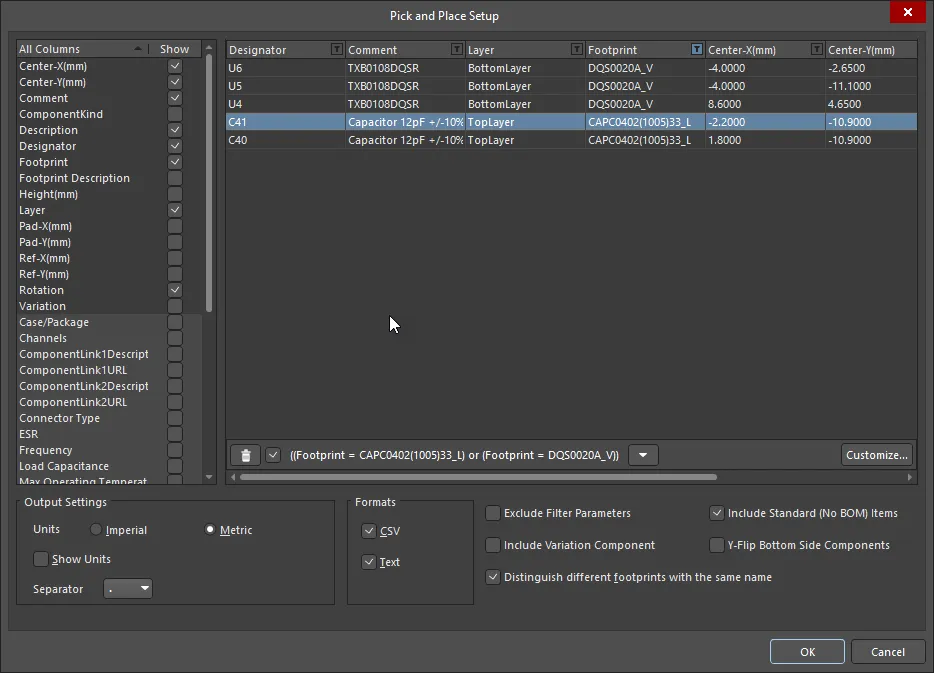
The required report is configured in the Pick and Place Setup dialog.

The Pick and Place Setup dialog
Options and Controls of the Pick and Place Setup Dialog
-
All Columns - a list of parameters from which you can choose to be included in the output file. Enable the Show column of the parameters you want to include in the output. The location information is expressed in three ways, corresponding to the three methods by which a component footprint's reference point can be specified in the source PCB library:
- Center X, Center Y - coordinates for the component's center point (calculated as the middle point in between the most outer pad locations)
- Ref X, Ref Y - coordinates for the component's user-defined reference point (the footprint's origin)
- Pad X, Pad Y - coordinates for Pad 1 of the component.
- Grid region - this region is a preview of the information that will be included in the output file.
-
Output Settings
- Units - use this region to specify whether to use Imperial or Metric units of measurement for the component location coordinates.
- Show Units - enable to show the units.
- Separator - select the desired unit separator from the drop-down.
- Formats - select in which format (CSV and/or Text) you want to generate output.
- Exclude Filter Parameters - enable to exclude parameters being used for filtering (refer to the Tips section below for more information).
- Include Variation Component - enable to include variants.
- Distinguish different footprints with the same name - when enabled, if one of the footprints with the same name has been modified, only the modified footprint is changed in the output. When the option is not enabled, all footprints with the same name will show as modified in the output.
- Include Standard (No BOM) Items - enable to include standard components to support fiducials.
- Y-Flip Bottom Side Components - enable this option to reverse a sign of the Ref-Y and Pad-Y values of components on the bottom layer.
Filtering
When filtering has been applied, the Pick and Place Setup dialog appears as shown above. Additional controls in this variation include:
-
 - click to delete the filtering displayed to the right. Use the checkbox to the right to enable/disable the filtering rather than deleting it fully.
- Down arrow - click to access a list of the previous filtering. Choose the desired filtering to filter the current grid.
- Customize - click to open the Filter builder dialog to create more sophisticated and complex filters.
Preparing Assembly Testpoint Reports
The assembly testpoint report generator produces a report (in txt and/or csv and/or IPC-D-356A formats) of all pads and vias that are setup for use as assembly testpoints.
Refer to the Assigning Testpoints on the Board page to learn more about assigning testpoints in a PCB design.
Assembly Testpoint Report output options are configured using the Assembly Testpoint Setup dialog.

The AssemblyTestpoint Setup dialog