When schematics were originally captured on paper, it was often on a single sheet of paper large enough to fill a big drafting table, which was reproduced on a dedicated, large-format copier. Times have changed, now schematics are captured on a desktop PC, stored on a server, and printed on a small-format laser printer.
This change means that even a simple design can be more easily displayed and understood if it is presented on multiple schematic sheets. Even when the design is not particularly complicated, there can be advantages in organizing it across multiple sheets.
For example, the design may include various modular elements. Maintaining these modules as individual documents allows several designers to work on a project at the same time. Breaking the design into logical modules greatly enhances the readability of the design too, an important consideration for those that need to read and interpret the schematic later in the life of that product. Another advantage is that when a design is structured over a number of sheets with fewer components on each, small format printing, such as laser printers, can be used.
There are two decisions to make if you plan to spread your design over multiple sheets:
-
the structural relationship of the sheets, and
-
the method employed for electrical connectivity between the circuitry on those sheets.
Your choice will vary according to the size and type of each project, and your personal preferences.
This article focuses on the structural relationships between the sheets, how it works, and the tools and techniques available to create a multi-sheet design. To learn more about how connectivity is created, refer to the Creating Connectivity article.
Flat or Hierarchical Design
As mentioned, as the designer you need to decide how the schematic sheets are organized, and how the connectivity is established between those sheets. These are not separate decisions though, as you choose the structure you will also need to choose how the connections between those sheets are going to be created.
There are two approaches to structuring a multi-sheet design: either flat or hierarchical.
Both approaches are valid; each has its own strengths and weaknesses. A flat design will be quicker to create but harder for others to follow signals and interpret the functionality, especially from a printed copy. A hierarchical design will take longer to draw as there are more steps to create the connectivity with the reward being a design for which others more easily interpret its functionality and follow the signals across the sheets. Hierarchical design is also important for design reuse and an essential part of a multi-channel design.
The technique used to connect a child sheet to the parent sheet is the same for both flat and hierarchical designs - it is how the connectivity is created that determines if it is a flat or hierarchical design.
Flat Design
You can think of a flat design as if a large schematic sheet has been cut up into several smaller sheets - in a flat design all sheets exist on the same level. The connectivity in a flat design is created directly from any sheet to any other sheet - this type of connectivity is referred to as horizontal connectivity.
The use of a top sheet is optional in a flat design. If one is included, it will have a sheet symbol for each of the sheets in the design, but cannot include any wiring. There can be any number of sheets in a flat design.

First image - the flat design has no top sheet; second image - the same design has a top sheet. Note that the top sheet has no wiring. It simply shows the sheets in the design.
Both of the images above show a flat design, the version on the left does not have a top sheet, but the version on the right does. For a small design that only has two or three schematic sheets in it, you might decide that a top sheet does not add any value. Once the sheet count gets higher, a top sheet can help the reader understand the functionality of the circuit design from the way that the logical blocks (Sheet Symbols) are arranged on the sheet. All sheets in the design appear at the same level in the Projects panel because there is no hierarchy.
Sheet Symbol

A placed Sheet Symbol
Summary
A sheet symbol is an electrical design primitive. It is used to represent a sub-sheet in a multi-sheet hierarchical design. Sheet symbols include sheet entry symbols, which provide a connection point for signals between the parent and child sheets in a hierarchical design, similar to how Ports provide connections between sheets in a flat-sheet design.
Availability
Sheet symbols are available for placement in the Schematic Editor only. Use one of the following methods to access the placement command:
-
Choose Place » Sheet Symbol from the main menus.
-
Click the Sheet Symbol button (
 ) in the graphic objects drop-down on the Active Bar located at the top of the design space. (Click and hold an Active Bar button to access other related commands. Once a command has been used, it will become the top-most item on that section of the Active Bar.)
-
Right-click in the design space then choose Place » Sheet Symbol from the context menu.
-
Click on the Wiring toolbar.
Placement
After launching the command, the cursor will change to a cross-hair and enter sheet symbol placement mode. Placement is made by performing the following actions:
-
Click or press Enter to anchor the first corner of the sheet symbol.
-
Move the cursor to adjust the size of the sheet symbol then click or press Enter to complete placement.
-
Continue placing further sheet symbols or right-click or press Esc to exit placement mode.
Additional actions that can be performed during placement while the sheet symbol is still floating on the cursor and before its first corner is anchored are:
-
Press the Tab key to access the Sheet Symbol mode of the Properties panel from where properties for the sheet symbol can be changed on the fly. Click the design space pause button overlay (
 ) to resume placement.
-
Press and hold the Alt key to constrain the direction of movement to the horizontal or vertical axis depending on the initial direction of movement.
-
Press the Spacebar to rotate the sheet symbol counterclockwise or Shift+Spacebar for clockwise rotation. Rotation is in increments of 90°.
-
Press the X or Y keys to mirror the sheet symbol along the X-axis or Y-axis.
While attributes can be modified during placement (
Tab to access the
Properties panel), keep in mind that these will become the default settings for further placement unless the
Permanent option on the
Schematic – Defaults page of the
Preferences dialog is enabled. When this option is enabled, changes made will affect only the object being placed and subsequent objects placed during the same placement session.
Graphical Editing
This method of editing allows you to select a placed sheet symbol object directly in the design space and graphically change its size, shape or location.
When a sheet symbol object is selected, you can click and drag the editing handles to resize the sheet symbol.

A selected Sheet Symbol
Click anywhere on the sheet symbol away from editing handles and drag to reposition it. While dragging, the sheet symbol can be rotated (Spacebar/Shift+Spacebar) or mirrored (X or Y keys to mirror along the X-axis or Y-axis).
Resizing the sheet symbol will not affect the absolute positions of any defined sheet entries within.
The sheet symbol's Designator and File Name text fields can only be resized by changing the size of the font used (accessed through the appropriate object's Properties panels). As such, editing handles are not available when either of those objects are selected.

Selected Designator and Filename for a sheet symbol
-
Click anywhere inside the dashed box and drag to reposition the text object as required. While dragging, the text can be rotated (Spacebar/Shift+Spacebar) or mirrored (X or Y keys to mirror along the X-axis or Y-axis).
-
The text for an object can be edited in-place by:
-
Single-clicking the designator or filename text to select it.
-
Single-clicking again (or pressing Enter) to enter the in-place editing mode. Sufficient time between each click should be given to ensure the software does not interpret the two single-clicks as one double-click (which would open the associated Properties panel).
-
To finish editing in-place text, press Enter or use the mouse to click away from the text object.
If attempting to graphically modify an object that has its Locked property enabled, a dialog will appear asking for confirmation to proceed with the edit. If the Protect Locked Objects option is enabled on the Schematic – Graphical Editing page of the Preferences dialog, and the Locked option for that design object is enabled as well, then that object cannot be selected or graphically edited. Click the locked object to select it then disable the Locked property in the List panel or disable the Protect Locked Objects option to graphically edit the object.
Non-Graphical Editing
The following methods of non-graphical editing are available.
Editing via the Sheet Symbol Dialog or Properties Panel
Properties page: Sheet Symbol Properties
This method of editing uses the associated Sheet Symbol dialog and the Properties panel mode to modify the properties of a sheet symbol object.

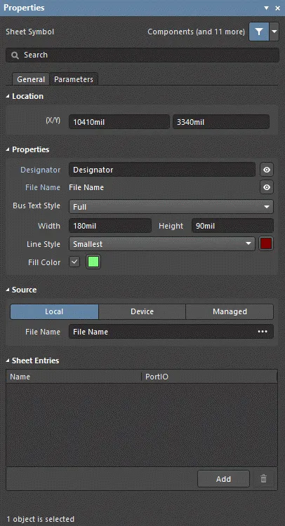
The Sheet Symbol dialog, on the left, and the Sheet Symbol mode of the Properties panel on the right
After placement, the Sheet Symbol dialog can be accessed by:
-
Double-clicking on the placed sheet symbol object.
-
Placing the cursor over the sheet symbol object, right-click, then choose Properties from the context menu.
During placement, the Sheet Symbol mode of the Properties panel can be accessed by pressing the Tab key. Once the sheet symbol is placed, all options appear.
After placement, the Sheet Symbol mode of the Properties panel can be accessed in one of the following ways:
-
If the Properties panel is already active, by selecting the sheet symbol object.
-
After selecting the sheet symbol object, select the Properties panel from the Panels button at the bottom right of the design space or select View » Panels » Properties.
If the
Double Click Runs Interactive Properties option is disabled (default) on the
Schematic - Graphical Editing page of the
Preferences dialog, when the primitive is double-clicked or you right-click on a selected primitive then choose
Properties, the dialog will open. When the
Double Click Runs Interactive Properties option is enabled, the
Properties panel will open.
While the options are the same in the dialog and the panel, the order and placement of the options may differ slightly.
The sheet symbol properties can be accessed prior to entering placement mode from the
Schematic – Defaults page of the
Preferences dialog. This allows the default properties for the sheet symbol object to be changed, which will be applied when placing subsequent sheet symbols.
Editing Multiple Objects
The Properties panel supports multiple object editing, where the property settings that are identical in all currently selected objects may be modified. When multiples of the same object type are selected manually, via the Find Similar Objects dialog or through a SCH Filter or SCH List panel, a Properties panel field entry that is not shown as an asterisk (*) can be edited for all selected objects.
Editing via a List Panel
Panel pages: List Panels, SCH Filter
A List panel allows you to display design objects from one or more documents in tabular format, enabling quick inspection and modification of object attributes. Used in conjunction with appropriate filtering - by using the applicable Filter panel, or the Find Similar Objects dialog - it enables the display of just those objects falling under the scope of the active filter – allowing you to target and edit multiple design objects with greater accuracy and efficiency.
Sheet Symbol Actions
Formatting Designator and File Name
The sheet symbol Designator and File Name fields can be formatted independently of the sheet symbol. The corresponding Properties panels can be accessed using the after-placement methods described above (replacing sheet symbol with the relevant object whose properties you want to view/modify).
The
File Name of the sheet symbol (set in the
Sheet Symbol mode of the
Properties panel) must be set to the file name of the schematic sheet that the symbol represents.
Right-click Sheet Symbol Commands
Right-click over a placed sheet symbol to access a context-sensitive menu, from which the following commands are available (on the Sheet Symbol Actions sub-menu) that act on that sheet symbol (or all currently selected sheet symbols, where applicable).

-
Open SubSheet "<SheetName.SchDoc>" - use to access the child sheet referenced by the symbol, which will be opened (if not already) and made the active document in the main design window.
-
Create Sheet From Sheet Symbol - use to create a new schematic document from the sheet symbol and add ports to that document corresponding to each of the sheet entries on the symbol. In this way, you can automatically create the sub-sheets for a multi-sheet schematic design based on the sheet symbols you have created and placed on the top sheet.
The schematic document that is created is named using the entry in the sheet symbol's File Name field. You can either enter the intended name for the document in this field before launching the command, complete with extension (i.e. DocumentName.SchDoc) or leave the name blank and enter the name when saving the generated document at a later stage.
Care should be taken when creating a sheet from a sheet symbol when a sheet with that file name already exists. A new sheet with the same file name will be created. The duplication can be resolved when saving by either saving the new sheet with a different name or overwriting the existing sheet if required.
-
Rename Child Sheet (can also be accessed by choosing the Design » Rename Child Sheet command from the main menus) - use to quickly rename the child schematic sheet referenced by the sheet symbol. The Rename Child Sheet dialog will open.

The Rename Child Sheet dialog
Specify the new name for the schematic sheet in the New child sheet file name field, making sure to keep the .SchDoc extension. Also determine how the renaming should proceed - the scope of the operation - from the following options:
-
Rename child document and update all relevant sheet symbols in the current project – enable this option to rename the child sheet and update all sheet symbols on source schematics in the active project that point to this sheet. The File Name for each sheet symbol will be updated to reflect the newly named child sheet.
-
Rename child document and update all relevant sheet symbols in the current workspace – enable this option to rename the child sheet and update all sheet symbols on source schematics across all open projects that point to this sheet. The File Name for each sheet symbol will be updated to reflect the newly named child sheet.
-
Copy the child document and only update the current sheet symbol – enable this option to take a copy of the child sheet before renaming the original. Only the current sheet symbol (under the cursor) is updated using this option. The File Name field for the sheet symbol will be updated to reference the copied child sheet.
Taking a copy of the child sheet is useful when the current child sheet is referenced by multiple sheet symbols, and one sheet symbol needs to reference a modified version of the circuitry contained on that sheet. You still want to keep the original sheet, you are simply creating a renamed copy of this sheet with which to point to from a single sheet symbol. You can then modify the content of the copied sheet as required.
-
Synchronize Sheet Entries and Ports - use to synchronize the sheet entries and sub-sheet ports for the sheet symbol. The Synchronize Ports To Sheet Entries dialog will open. Use this dialog to ensure that all sheet entries on the sheet symbol are matched to ports on the referenced child sheet below, both in terms of name and I/O Type.
-
Flip Sheet Symbol Along X - use to flip the sheet symbol along the X-axis. The sheet entries associated with the symbol will essentially be swapped to the opposite side of the symbol (in the horizontal plane). Those on the left will be repositioned on the right and vice-versa. The I/O Type of sheet entries is not altered.

Example of flipping a sheet symbol along the X-axis
If a single or multiple sheet symbols are currently selected, the command will appear as Flip Selected Sheet Symbols Along X. The command is also available from the Edit » Move sub-menu of the main menus and from the Active Bar. When flipping multiple selected sheet symbols, the symbols will be flipped along an imaginary vertical line that is located mid-way between the bounding extents of the symbols in the selection.
-
Flip Sheet Symbol Along Y - use to flip the sheet symbol along the Y-axis. The sheet entries associated with the symbol will essentially be swapped to the opposite side of the symbol (in the vertical plane). Those at the top will be repositioned at the bottom and vice-versa. The I/O Type of sheet entries is not altered.

Example of flipping a sheet symbol along the Y-axis
If a single or multiple sheet symbols are currently selected, the command will appear as Flip Selected Sheet Symbols Along Y. The command is also available from the Edit » Move sub-menu of the main menus and from the Active Bar. When flipping multiple selected sheet symbols, the symbols will be flipped along an imaginary horizontal line that is located mid-way between the bounding extents of the symbols in the selection.
-
Toggle All Sheet Entries IO Type in Sheet Symbol - use to toggle the I/O Type for all sheet entries in the sheet symbol simultaneously where applicable. It is also available by clicking Toggle All Sheet Entries IO Type In (Selected) Sheet Symbols from the Edit » Move main menu or from the Active Bar.
 Example result of toggling sheet entry I/O
The actual change depends on the current PortIO Type as follows:
-
Unspecified remains Unspecified.
-
Output changes to Input.
-
Input changes to Output.
-
Bidirectional remains Bidirectional.
Notes
-
If a group of sheet entries is pasted into a selected sheet symbol and those entries fall outside the current bounds of the symbol, it will automatically be resized to accommodate them.
-
By using sheet symbol instantiation, multiple channels on the same sub-sheet can be referenced from a single sheet symbol. The syntax used involves the use of the Repeat keyword in the sheet symbol's Designator field and takes the form:
Repeat(SheetSymbolDesignator, FirstInstance, LastInstance),
where SheetSymbolDesignator is the base name for the sheet symbol and FirstInstance and LastInstance together define the number of channels to be instantiated.
When the
New Indexing of Sheet Symbols option is enabled on the
Options tab of the Project Options dialog, any digit or number may be used as the first or last index of a repeated Sheet Symbol, including 0; the last index must always be larger than the first index and negative numbers are not allowed.
-
Multiple sub-sheets may be referenced by a single sheet symbol. Separate each filename by a semi-colon in the File Name field. With the effective use of off-sheet connectors placed on the sub-sheets, you can spread a section of your design over multiple sheets treating them as though they are one giant (flat) sheet. Note, however, that use of off-sheet connectors is only possible for sheets referenced by the same sheet symbol.
-
The
SheetSymbolDesignator special string is available for use. This special string can be placed on a child schematic sheet to display the designator of the associated Sheet Symbol object that is placed on the parent schematic sheet. This special string can also be used in a multi-channel design. Select a compiled tab of the child schematic sheet to display the converted value of the special string.
-
You can reverse the order that selected sheet entries appear along a side of a parent sheet symbol by choosing the Edit » Move » Reverse Selected Sheet Entries Order command, from the main menus, or locating and using the Reverse Selected Sheet Entries Order command on the Active Bar. Two or more sheet entries must be selected for a particular side of a sheet symbol, in order for the command to have effect. You can simultaneously reorder sheet entries along different sides of the same parent sheet symbol, and across different sheet symbols on the active schematic sheet. After launching the command, the reordering will take place. The reordering is achieved by mirroring the positions of the selected sheet entries - along a particular sheet symbol side - about an imaginary line at the mid point of the distance between the extents of the two outer-most selected sheet entries. The I/O Type of a sheet entry is not changed by the reordering.
Sheet Symbol Properties
Schematic editor object properties are definable options that specify the visual style, content and behavior of the placed object. The property settings for each type of object are defined in two different ways:
-
Pre-placement settings – most Sheet Symbol object properties, or those that can logically be pre-defined, are available as editable default settings on the Schematic - Defaults page of the Preferences dialog (access from the
 button at the top-right of the design space). Select the object in the Primitive List to reveal its options on the right.

-
Post-placement settings – all Sheet Symbol object properties are available for editing in the Sheet Symbol dialog and the Properties panel when a placed Sheet Symbol is selected in the design space.
If the
Double Click Runs Interactive Properties option is disabled (default) on the
Schematic - Graphical Editing page of the
Preferences dialog, when the primitive is double-clicked or you right-click on a selected primitive then choose
Properties, the dialog will open. When the
Double Click Runs Interactive Properties option is enabled, the
Properties panel will open.
While the options are the same in the dialog and the panel, the order and placement of the options may differ slightly.
In the below properties listing, options that are not available as default settings in the Preferences dialog are noted as "Properties panel only".
General Tab
Location (Properties panel only)
-
(X/Y)
-
X (first field) - the current X (horizontal) coordinate of the reference point of the object, relative to the current design space origin. Edit to change the X position of the object. The value can be entered in either metric or imperial; include the units when entering a value whose units are not the current default.
-
Y (second field) - The current Y (vertical) coordinate of the reference point of the object, relative to the current origin. Edit to change the Y position of the object. The value can be entered in either metric or imperial; include the units when entering a value whose units are not the current default.
Properties
Source (Properties panel only)
-
Local / Device / Managed - the source of the file.
-
File Name - displays the current schematic document referenced by the sheet symbol. It is this field that provides the link between the sheet symbol and the schematic sub-sheet that the symbol represents. Click
 to open the
 ![]() Choose Document to Reference dialog to choose the required target sub-sheet. The dialog presents a listing of all source schematic sheets in the project (with the exception of the sheet upon which the symbol is currently placed).
Choose Document to Reference dialog to choose the required target sub-sheet. The dialog presents a listing of all source schematic sheets in the project (with the exception of the sheet upon which the symbol is currently placed).
Multiple sub-sheets may be referenced by a single sheet symbol. Separate each file name by a semi-colon in the File Name field. With the effective use of off-sheet connectors placed on the sub-sheets, you can effectively spread a section of your design over multiple sheets, treated as though they were one giant (flat) sheet. Note, however, that use of off-sheet connectors is only possible for sheets referenced by the same sheet symbol.
Sheet Entries (Properties panel only)
-
Grid - lists the Name and PortIO Type of all of the sheet entries currently defined for the sheet symbol. When there are sheet entries in the grid, the following additional options are available when an entry is selected:
-
Font - click to configure the font style of the sheet entry.
-
Other - click to open a drop-down to change additional options:
-
Kind - use the drop-down to select the kind of sheet entry.
-
Border Color - click to access controls to choose the border color.
-
Fill Color - click to access controls to choose the fill color.
-
Add - click to add a sheet entry. Use
 to delete a selected entry from the table.
Parameters Tab

Parameters
-
Grid - lists the Name and Value of all of the parameters currently defined for the sheet symbol. When there are parameters in the grid, the following additional options are available when a parameter is selected:
-
Font - click to configure the font style of the parameter.
-
Other - click to open a drop-down to change additional options:
-
Show Parameter Name - enable to show the parameter name in the design space.
-
Allow Synchronization with Database - enable to synchronize with the database. This option is used to control if the comment can be updated. By default, these options are enabled to always allow synchronization with the source library/database. You may disable this option to prevent that comment from being included in an update process.
-
X/Y - enter the X and Y coordinates desired.
-
Rotation - use the drop-down to select the rotation.
-
Autoposition - check to enable auto-positioning, meaning that the text will remain in the chosen position as the component is moved and rotated.
-
Add - click to add a parameter. Use to delete a selected entry from the table.
Sheet Symbol Designator

The Sheet Symbol Designator
Summary
The sheet symbol designator is a non-electrical child object of an electrical design primitive. It is used to provide a sheet symbol with a meaningful name that will distinguish it from other sheet symbols placed on the same schematic sheet. Typically the name will reflect the overall function of the schematic sub-sheet that the symbol represents.
Availability and Placement
The sheet symbol designator is automatically placed when the parent component part object is placed. It is not a design object that the user can directly place.
Any changes made to the
Designator field during sheet symbol placement will cause the default properties for the sheet symbol designator object to be updated unless the
Permanent option on the
Schematic - Defaults page of the
Preferences dialog is enabled. When this option is enabled, changes made will affect only the designator of the sheet symbol object being placed and subsequent sheet symbol objects placed during the same placement session.
Graphical Editing
This method of editing allows you to select a sheet symbol designator object directly in the design space and change its location graphically. Sheet symbol designators can only be adjusted with respect to their size by changing the size of the Font in the Properties panel. As such, editing handles are not available when the sheet symbol designator object is selected:

A selected sheet symbol designator
Click anywhere inside the dashed box then drag to reposition the sheet symbol designator object as required. The object can be rotated or flipped while dragging:
-
Press the Tab key to access the Properties panel from where properties for the sheet symbol designator can be changed on the fly.
-
Press the Alt key to constrain the direction of movement to the horizontal or vertical axis depending on the initial direction of movement.
-
Press the Spacebar to rotate the sheet symbol designator counter-clockwise or Shift+Spacebar for clockwise rotation. Rotation is in increments of 90°.
-
Press the X or Y keys to mirror the sheet symbol designator along the X-axis or Y-axis.
If the Enable
In-Place Editing option is enabled on the
Schematic - General page of the
Preferences dialog, you will be able to edit the name for the sheet symbol designator directly in the design space. Select the designator then click once to invoke the feature. Type the new name as required then click away from the sheet symbol designator field or press
Enter to effect the change.
If attempting to graphically modify an object that has its Locked property enabled, a dialog will appear asking for confirmation to proceed with the edit. If the Protect Locked Objects option is enabled on the Schematic – Graphical Editing page of the Preferences dialog, and the Locked option for that design object is enabled as well, then that object cannot be selected or graphically edited. Click the locked object to select it then disable the Locked property in the List panel or disable the Protect Locked Objects option to graphically edit the object.
Non-Graphical Editing
The following methods of non-graphical editing are available.
Editing via the Parameter Dialog or Properties Panel
Panel page: Sheet Symbol Designator Properties
This method of editing uses the associated Parameter dialog and the Properties panel mode to modify the properties of a sheet symbol designator object.

 The Parameter dialog, on the left, and the Parameter mode of the Properties panel on the right
After placement, the Parameter dialog can be accessed by:
-
Double-clicking on the placed sheet symbol designator object.
-
Placing the cursor over the sheet symbol designator object, right-clicking then choosing Properties from the context menu.
During placement, the Parameter mode of the Properties panel can be accessed by pressing the Tab key. Once the sheet symbol designator is placed, all options appear.
After placement, the Parameter mode of the Properties panel can be accessed in one of the following ways:
-
If the Properties panel is already active, by selecting the sheet symbol designator object.
-
After selecting the sheet symbol designator object, select the Properties panel from the Panels button at the bottom right of the design space or select View » Panels » Properties.
If the
Double Click Runs Interactive Properties option is disabled (default) on the
Schematic - Graphical Editing page of the
Preferences dialog, when the primitive is double-clicked or you right-click on a selected primitive then choose
Properties, the dialog will open. When the
Double Click Runs Interactive Properties option is enabled, the
Properties panel will open.
While the options are the same in the dialog and the panel, the order and placement of the options may differ slightly.
The sheet symbol designator properties can be accessed prior to entering placement mode from the
Schematic – Defaults page of the
Preferences dialog. This allows the default properties for the sheet symbol designator object to be changed, which will be applied when placing subsequent sheet symbol designators.
Editing Multiple Objects
The Properties panel supports multiple object editing, where the property settings that are identical in all currently selected objects may be modified. When multiples of the same object type are selected manually, via the Find Similar Objects dialog or through a Filter or List panel, a Properties panel field entry that is not shown as an asterisk (*) may be edited for all selected objects.
Editing via a List Panel
Panel pages: List Panels, SCH Filter, SCHLIB Filter
A List panel allows you to display design objects from one or more documents in tabular format, enabling quick inspection and modification of object attributes. Used in conjunction with appropriate filtering - by using the applicable Filter panel, or the Find Similar Objects dialog - it enables the display of just those objects falling under the scope of the active filter – allowing you to target and edit multiple design objects with greater accuracy and efficiency.
Notes
-
While text frames can be rotated or mirrored along the X or Y axis, this has no effect on the orientation of the text within.
-
For simple one-line text annotations, consider using the Text String object.
-
By using sheet symbol instantiation, multiple channels on the same sub-sheet can be referenced from a single sheet symbol. The syntax used involves the use of the Repeat keyword in the sheet symbol designator field and takes the form:
Repeat(SheetSymbolDesignator, FirstInstance, LastInstance).

Using Repeat keyword
SheetSymbolDesignator is the base name for the sheet symbol and FirstInstance and LastInstance together define the number of channels to be instantiated. When the project is built, the Compiler instantiates the channel the required number of times as it builds the internal compiled model, using a chosen annotation scheme to uniquely identify each component in each channel. The channel sub-sheet is not duplicated. Instead, once compiled, a separate tab appears at the bottom of the sub-sheet document in the main design window for each channel on that sheet.
When the
New Indexing of Sheet Symbols option is enabled on the
Options tab of the Project Options dialog, any digit or number may be used as the first or last index of a repeated Sheet Symbol, including 0; the last index must always be larger than the first index and negative numbers are not allowed.
-
The
SheetSymbolDesignator special string is available for use. This special string can be placed on a child schematic sheet to display the designator of the associated Sheet Symbol object that is placed on the parent schematic sheet. This special string can also be used in a multi-channel design. Select a compiled tab of the child schematic sheet to display the converted value of the special string.
Sheet Symbol Designator Properties
Schematic editor object properties are definable options that specify the visual style, content and behavior of the placed object. The property settings for each type of object are defined in two different ways:
-
Pre-placement settings – most Sheet Symbol Designator object properties, or those that can logically be pre-defined, are available as editable default settings on the Schematic - Defaults page of the Preferences dialog (access from the button at the top-right of the design space). Select the object in the Primitive List to reveal its options on the right.

-
Post-placement settings – all Sheet Symbol Designator object properties are available for editing in the Parameter dialog and the Properties panel when a placed Sheet Symbol Designator is selected in the design space.
If the
Double Click Runs Interactive Properties option is disabled (default) on the
Schematic - Graphical Editing page of the
Preferences dialog, when the primitive is double-clicked or you right-click on a selected primitive then choose
Properties, the dialog will open. When the
Double Click Runs Interactive Properties option is enabled, the
Properties panel will open.
While the options are the same in the dialog and the panel, the order and placement of the options may differ slightly.
In the below properties listing, options that are not available as default settings in the Preferences dialog are noted as "Properties panel only".
Location (Properties panel only)
-
(X/Y)
-
X (first field) - the current X (horizontal) coordinate of the reference point of the object, relative to the current design space origin. Edit to change the X position of the object. The value can be entered in either metric or imperial; include the units when entering a value whose units are not the current default.
-
Y (second field) - The current Y (vertical) coordinate of the reference point of the object, relative to the current origin. Edit to change the Y position of the object. The value can be entered in either metric or imperial; include the units when entering a value whose units are not the current default.
-
Rotation - use the drop-down to select the rotation.
Properties
Sheet Symbol File Name

Sheet Symbol File Name
Summary
The Sheet Symbol File Name is a non-electrical child object of an electrical design primitive. It provides the link between the sheet symbol and the schematic sub-sheet that the symbol represents.
Availability and Placement
The Sheet Symbol File Name is automatically placed when the parent sheet symbol object is placed. It is not a design object that the user can directly place.
While attributes can be modified during placement (
Tab to access the
Properties panel), keep in mind that these will become the default settings for further placement unless the
Permanent option on the
Schematic – Defaults page of the
Preferences dialog is enabled. When this option is enabled, changes made will affect only the object being placed and subsequent objects placed during the same placement session.
Graphical Editing
This method of editing allows you to select a sheet symbol file Name object directly in the design space and change its location graphically. Sheet symbol file Names can only be adjusted with respect to their size by changing the size of the Font in the Properties panel. As such, editing handles are not available when the sheet symbol file name object is selected.
 Click anywhere inside the dashed box and drag to reposition the sheet symbol filename object as required. The object can be rotated or flipped while dragging.
Press the Spacebar to rotate the file name. Rotation is counterclockwise in increments of 90°.
If the Enable
In-Place Editing option is enabled on the
Schematic - General page of the
Preferences dialog, you will be able to edit the name for the sheet symbol file name directly in the design space. Select the designator then click once to invoke the feature. Type the new name as required then click away from the sheet symbol file name or press
Enter to effect the change.
If attempting to graphically modify an object that has its Locked property enabled, a dialog will appear asking for confirmation to proceed with the edit. If the Protect Locked Objects option is enabled on the Schematic – Graphical Editing page of the Preferences dialog, and the Locked option for that design object is enabled as well, then that object cannot be selected or graphically edited. Click the locked object to select it then disable the Locked property in the List panel or disable the Protect Locked Objects option to graphically edit the object.
Non-Graphical Editing
The following methods of non-graphical editing are available.
Editing via the Parameter Dialog or Properties Panel
Panel page: Sheet Symbol File Name Properties
This method of editing uses the associated Parameter dialog and the Properties panel mode to modify the properties of a sheet symbol file name object.

 The Parameter dialog, on the left, and the Parameter mode of the Properties panel on the right
After placement, the Parameter dialog can be accessed by:
-
Double-clicking on the placed sheet symbol object.
-
Place the cursor over the sheet symbol object, right-click, then choose Properties from the context menu.
During placement, the Parameter mode of the Properties panel can be accessed by pressing the Tab key. Once the sheet symbol is placed, all options appear.
After placement, the Parameter mode of the Properties panel can be accessed in one of the following ways:
-
If the Properties panel is already active, by selecting the Sheet Symbol object.
-
After selecting the sheet symbol object, select the Properties panel from the Panels button at the bottom right of the design space or select View » Panels » Properties.
If the
Double Click Runs Interactive Properties option is disabled (default) on the
Schematic - Graphical Editing page of the
Preferences dialog, when the primitive is double-clicked or you right-click on a selected primitive then choose
Properties, the dialog will open. When the
Double Click Runs Interactive Properties option is enabled, the
Properties panel will open.
While the options are the same in the dialog and the panel, the order and placement of the options may differ slightly.
The sheet symbol file name properties can be accessed prior to entering placement mode from the
Schematic – Defaults page of the
Preferences dialog. This allows the default properties for the sheet symbol file name object to be changed, which will be applied when placing subsequent sheet symbol file names.
Editing Multiple Objects
The Properties panel supports multiple object editing, where the property settings that are identical in all currently selected objects may be modified. When multiples of the same object type are selected manually, via the Find Similar Objects dialog or through a Filter or List panel, a Properties panel field entry that is not shown as an asterisk (*) may be edited for all selected objects.
Editing via a List Panel
Panel pages: List Panels, SCH Filter, SCHLIB Filter
A List panel allows you to display design objects from one or more documents in tabular format, enabling quick inspection and modification of object attributes. Used in conjunction with appropriate filtering - by using the applicable Filter panel, or the Find Similar Objects dialog - it enables the display of just those objects falling under the scope of the active filter – allowing you to target and edit multiple design objects with greater accuracy and efficiency.
Sheet Symbol Filename Properties
Schematic Editor object properties are definable options that specify the visual style, content and behavior of the placed object. The property settings for each type of object are defined in two different ways:
-
Pre-placement settings – most Sheet Symbol Filename object properties, or those that can logically be pre-defined, are available as editable default settings on the Schematic - Defaults page of the Preferences dialog (access from the button at the top-right of the design space). Select the object in the Primitive List to reveal its options on the right.

-
Post-placement settings – all Sheet Symbol Filename object properties are available for editing in the Parameter dialog and the Properties panel when a placed Sheet Symbol Filename is selected in the design space.
If the
Double Click Runs Interactive Properties option is disabled (default) on the
Schematic - Graphical Editing page of the
Preferences dialog, when the primitive is double-clicked or you right-click on a selected primitive then choose
Properties, the dialog will open. When the
Double Click Runs Interactive Properties option is enabled, the
Properties panel will open.
While the options are the same in the dialog and the panel, the order and placement of the options may differ slightly.
In the below properties listing, options that are not available as default settings in the Preferences dialog are noted as "Properties panel only".
Location (Properties panel only)
-
Search - use this field to search for the desired text within the Properties panel. Once found, the text searched will be highlighted.
-
(X/Y)
-
X (first field) - the current X (horizontal) coordinate of the reference point of the object, relative to the current design space origin. Edit to change the X position of the object. The value can be entered in either metric or imperial; include the units when entering a value whose units are not the current default.
-
Y (second field) - The current Y (vertical) coordinate of the reference point of the object, relative to the current origin. Edit to change the Y position of the object. The value can be entered in either metric or imperial; include the units when entering a value whose units are not the current default.
-
Rotation - use the drop-down to select the rotation.
Properties
-
Sheet Symbol - the sheet symbol associated with this object.
-
Name - displays the name.
-
Value - displays the actual filename text. Use
 /
/  to determine whether the Value for the object is displayed or hidden. Check Autoposition to enable auto-positioning.
-
Font - use the controls to configure the font, font size, color, and special settings such as bold and underlining.
-
Justification - select the desired justification of the text.
Hierarchical Design
It is important to remember that for hierarchical designs, a project can contain only one top sheet. All other source documents must be referenced by sheet symbols. When performing a design validation, the
Multiple Top Level Documents violation check can be used to flag if this is not the case. In addition, no sheet symbol may reference the sheet it's on or any sheet higher up the ladder, as this will create an irresolvable loop in the structure.
A hierarchical design is one where the tree-like structure - or sheet-to-sheet relationships - in the design is represented. This is done with sheet symbols, which represent lower sheets in the design hierarchy. The symbol represents the sheet below, and the sheet entries in it represent (or connect to) the ports on the sheet below. The connectivity is through the Sheet Entries in those Sheet Symbols - not directly from the Ports on one sheet to the Ports on another sheet.
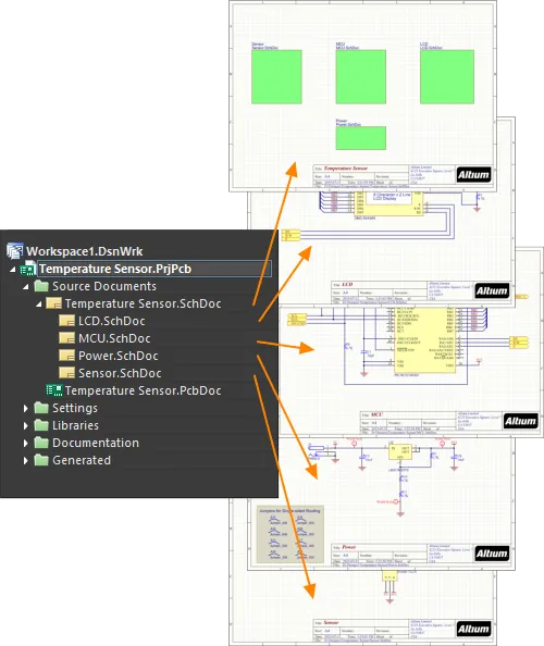
As in a flat design, the child sheet is identified by defining its filename in the sheet symbol. In a hierarchical design, that child sheet can also include sheet symbols, referencing lower-level sheets, thus creating another level in the hierarchy. The image below shows a hierarchical design, with 3 levels in the hierarchy.

In a hierarchical design, the structure shown in the tree is determined by the parent-to-child relationships created by the sheet symbols.
In a hierarchical design, a signal on a child sheet leaves the sheet via a Port, which connects upward to a matching Sheet Entry on the parent sheet. The parent sheet includes wiring that carries the child signal across to a Sheet Entry in another Sheet Symbol, it then travels down to a matching Port on the second child sheet, as shown in the image below.

This parent-child sheet structure can be defined to any depth, and there can be any number of sheets in a hierarchical design.
The connectivity between the sheets is determined by the Net Identifier Scope. This is set in the Options tab of the Options for Project dialog. To learn more about creating connectivity, read the Creating Connectivity page. Note that the Net Identifier Scope includes an Automatic option, unless you have unusual connectivity requirements, this option is a good choice.
The advantage of the hierarchical design is that it shows the reader the structure of the design and that the connectivity is completely predictable and easily traced since it is always from the child sheet up to the sheet symbol on the parent sheet.
Another advantage of a hierarchical design is that it provides the platform for the delivery of a sophisticated design reuse system. This system is delivered in two ways, depending on how the data is stored, either: file-based or server-based.
-
The file-based system is called Device Sheets, where you place an existing schematic from a library of Device Sheets directly into the design being created. To learn more about Device Sheets, refer to the Working with Device Sheets page.
-
The Workspace-based system is called Managed Schematic Sheets, where you place an existing schematic from a connected Workspace directly into the design being created. To learn more about Managed Sheets, refer to the Working with Managed Schematic Sheets page.
Port
 A placed Port
Summary
A port is an electrical design primitive. It is used to make an electrical connection between one schematic sheet and another sheet, or sheet symbol (through a corresponding sheet entry) in a design using multiple sheets (both flat and hierarchical designs). The name of the port defines the connection (i.e. a port on a schematic sheet connects to ports or sheet entries with the same name on other sheets in the project).
Note that the
Cross Reference feature identifies the locations of interconnected
Ports and positional grid references for interconnected off sheet connectors. For both types of schematic connection objects, the existing
Reports » Port Cross Reference » Add To Project command adds a cross-reference parameter based on the target sheet name and a positional grid reference.
Availability
Ports are available for placement in the Schematic Editor in the following ways:
-
Click Place » Port from the main menus.
-
Click the Port button (
 ) in the directives drop-down on the Active Bar, located at the top of the design space. (Click and hold an Active Bar button to access other related commands. Once a command has been used, it will become the topmost item on that section of the Active Bar.)
-
Right-click then select Place » Port.
Placement
After launching the command, the cursor will change to a cross-hair and you will enter port placement mode. Placement is made by performing the following sequence of actions:
-
Click or press Enter to anchor the left-hand edge of the port.
-
Move the cursor to adjust the length of the port as required then click or press Enter to complete placement of the port.
-
Continue placing further ports or right-click or press Esc to exit placement mode.
Additional actions that can be performed during placement while the port is still floating on the cursor and before its left-hand edge is anchored are:
-
Press the Tab key to pause the placement and access the Port mode of the Properties panel in which its properties can be changed on the fly. Click the design space pause button overlay () to resume placement.
-
Press the Spacebar to rotate the port counterclockwise or Shift+Spacebar for clockwise rotation. Rotation is in increments of 90°.
-
Press the X or Y keys to mirror the port along the X-axis or Y-axis.
While attributes can be modified during placement (Tab to access the associated Properties panel), keep in mind that these will become the default settings for further placement unless the Permanent option on the Schematic – Defaults page of the Preferences dialog is enabled. When this option is enabled, changes made will affect only the object being placed and subsequent objects placed during the same placement session.
Graphical Editing
This method of editing allows you to select a placed port object in the design space and graphically change its length, height, or location.
When a port object is selected, you can click and drag the editing handles to resize the port.
 A selected Port
Click anywhere on the port away from editing handles then drag to reposition it. While dragging, the port can be rotated (Spacebar/Shift+Spacebar) or mirrored (X or Y keys to mirror along the X-axis or Y-axis).
The name for the port object can be edited in-place by:
-
Single-click the port to select it.
-
Single-click again (or pressing Enter) to enter the in-place editing mode. Sufficient time between each click should be given to ensure the software does not interpret the two single clicks as one double-click (which would open the Properties panel).
-
To finish editing in-place text, press Enter or use the mouse to click away from the port.
-
Ports will automatically resize to accommodate the length/height of the port's name.
If attempting to graphically modify an object with its Locked property enabled, a dialog will appear asking for confirmation to proceed with the edit. If the Protect Locked Objects option is enabled on the Schematic – Graphical Editing page of the Preferences dialog, and the Locked option for that design object is enabled as well, then that object cannot be selected or graphically edited. Click the locked object to select it then disable the Locked property in the List panel or disable the Protect Locked Objects option to graphically edit the object.
Non-Graphical Editing
The following methods of non-graphical editing are available.
Editing via the Port Dialog or Properties Panel
Properties page: Port Properties
This method of editing uses the associated Port dialog and the Properties panel mode to modify the properties of a port object.

 The Port dialog, on the left, and the Port mode of the Properties panel on the right
After placement, the Port dialog can be accessed by:
-
Double-clicking on the placed port object.
-
Placing the cursor over the port object, right-clicking, then choosing Properties from the context menu.
During placement, the Port mode of the Properties panel can be accessed by pressing the Tab key. Once the port is placed, all options appear.
After placement, the Port mode of the Properties panel can be accessed in one of the following ways:
-
If the Properties panel is already active, by selecting the port object.
-
After selecting the port object, select the Properties panel from the Panels button at the bottom right of the design space or select View » Panels » Properties from the main menu.
If the
Double Click Runs Interactive Properties option is disabled (default) on the
Schematic - Graphical Editing page of the
Preferences dialog, when the primitive is double-clicked or you right-click on a selected primitive then choose
Properties, the dialog will open. When the
Double Click Runs Interactive Properties option is enabled, the
Properties panel will open.
While the options are the same in the dialog and the panel, the order and placement of the options may differ slightly.
The Port properties can be accessed prior to entering placement mode from the
Schematic – Defaults page of the
Preferences dialog. This allows the default properties for the port object to be changed, which will be applied when placing subsequent ports.
Editing Multiple Objects
The Properties panel supports multiple object editing, where the property settings that are identical in all currently selected objects may be modified. When multiples of the same object type are selected manually, via the Find Similar Objects dialog or through a SCH Filter or SCH List panel, a Properties panel field entry that is not shown as an asterisk (*) may be edited for all selected objects.
Editing via a List Panel
Panel pages: List Panels, SCH Filter
A List panel allows you to display design objects from one or more documents in tabular format, enabling quick inspection and modification of object attributes. Used in conjunction with appropriate filtering - by using the applicable Filter panel or the Find Similar Objects dialog - it enables the display of just those objects falling under the scope of the active filter – allowing you to target and edit multiple design objects with greater accuracy and efficiency.
Port Actions
Right-click over a placed port to pop-up a context-sensitive menu, from which the following commands are available (on the Port Actions sub-menu) that act on that port (or all currently selected ports, where applicable):
-
Jump to Sheet Entry <PortName> - use to jump to the port's corresponding sheet entry in the parent sheet symbol that references the sub-sheet on which the port resides.
-
Toggle Port IO Type - use to toggle the I/O Type for the port.
The actual change depends on the current I/O Type as follows:
-
Unspecified remains Unspecified.
-
Output changes to Input.
-
Input changes to Output.
-
Bidirectional remains Bidirectional.
If multiple ports are currently selected, the command will appear as Toggle Selected Ports IO Type. The command will apply to all selected ports.
-
Place Harness Connector of Type <HarnessConnectorType> - use to place a harness connector (complete with respective defined harness entries) for connection to the port.
This command is only available for a port that has a defined Harness Type.
-
Jump to Port <PortName> on <SheetName> - use to jump to another port with the same name on the indicated source schematic document.
Notes
-
The relationship between ports and sheet symbols is determined by the Net Identifier Scope chosen for the project. This scope is defined by setting the Net Identifier Scope option on the Project Options - Options dialog (Project » Project Options).
-
When set to Flat or Global, all ports with the same name within the same or different schematic documents are considered to be electrically connected.
-
When set to Hierarchical or Strict Hierarchical, ports only connect vertically to their corresponding sheet entries. They do not connect horizontally to other ports of the same name.
-
The I/O Type option in the Properties panel allows you to define the port's electrical type. Choose from either Input, Output, Bidirectional, or Unspecified. Note that the port will automatically display the I/O type if the Port Direction option in the Schematic – General page of the Preferences dialog is enabled.
-
To negate (include a bar over the top of) a port name, use one of the following methods:
-
Include a backslash character after each character in the name (e.g. E\N\A\B\L\E).
-
Enable the Single '\' Negation option on the Schematic - Graphical Editing page of the Preferences dialog, then include one backslash character at the start of the name (e.g., \ENABLE).
-
The default setting is for Port names to not be used to name nets. Enable the Allow Ports to Name Nets option in the Options tab of the Options for Project dialog if you want the Ports to be used to name their nets. If the option is disabled, a system-generated net name will be used if there is no net label or power object associated with that net, or if the Allow Sheet Entries to Name Nets option is not enabled in a hierarchical design. Learn more about How Nets are Named.
-
A port will automatically resize to accommodate the length/height of the port's name. Autosizing works regardless of how the text is entered (using the Port mode of the Properties panel or through in-place editing directly in the design space).
-
When a Port is connected to a Signal Harness, the Port becomes a Harness object. By default, the Port will change color to match the color of the Signal Harness.
-
When a Port is connected to a Harness Connector by a Signal Harness, the Harness Type in the Properties panel is automatically populated with the Harness Type of the Harness Connector. When a Port is connected to a Sheet Entry by a Signal Harness and the Sheet Entry has a Harness Type declared, the Port will become a Harness object and change to the color of the Signal Harness. If you move the Port away from the Harness Connector or the Sheet Entry, the Port will revert back to the default color.
-
By default, the font used for the port's Name follows the global document-level font set in the Document Font options in the Document Options mode of the Properties panel (when no objects are selected in the workspace). This can be overridden at the individual port-level with the Font settings in the Properties panel allowing you to fully control the textual presentation of ports as needed.
-
When an OrCAD design is imported through the use of the Import Wizard, custom port connectors are supported on the generated schematic document. Such ports will have the same graphics as in the original design. Learn more about Importing a Design from OrCAD.
-
When an xDX Designer design is imported through the use of the Import Wizard, custom ports are supported on the generated schematic document. Such ports will have the same graphics as in the original design. Learn more about Importing a Design from xDX Designer or DxDesigner.
This feature is in Open Beta and available when the Importer.UseCustomConnectors option is enabled in the Advanced Settings dialog.
Port Properties
Schematic Editor object properties are definable options that specify the visual style, content and behavior of the placed object. The property settings for each type of object are defined in two different ways:
-
Pre-placement settings – most Port object properties, or those that can logically be pre-defined, are available as editable default settings on the Schematic - Defaults page of the Preferences dialog (accessed from the button at the top-right of the design space). Select the object in the Primitive List to reveal its options on the right.

-
Post-placement settings – all Port object properties are available for editing in the Port dialog and the Properties panel when a placed Port is selected in the design space.
If the
Double Click Runs Interactive Properties option is disabled (default) on the
Schematic - Graphical Editing page of the
Preferences dialog, when the primitive is double-clicked or you right-click on a selected primitive then choose
Properties, the dialog will open. When the
Double Click Runs Interactive Properties option is enabled, the
Properties panel will open.
While the options are the same in the dialog and the panel, the order and placement of the options may differ slightly.
In the below properties listing, options that are not available as default settings in the Preferences dialog are noted as "Properties panel only".
General Tab
Location (Properties panel only)
-
(X/Y)
-
X (first field) - the current X (horizontal) coordinate of the reference point of the object, relative to the current design space origin. Edit to change the X position of the object. The value can be entered in either metric or imperial; include the units when entering a value whose units are not the current default.
-
Y (second field) - The current Y (vertical) coordinate of the reference point of the object, relative to the current origin. Edit to change the Y position of the object. The value can be entered in either metric or imperial; include the units when entering a value whose units are not the current default.
Properties
-
Name - the name of the port.
-
I/O Type - defines the electrical properties of the port. Select an option from the drop-down list.
This setting does not influence the connectivity of the circuit, however, it is considered during the running of an electrical rules check, which can be set to detect incompatible port directions.
-
Harness Type - use the drop-down to select the type of harness.
-
Cross Ref - this field displays cross-reference values that are applied to the port.
-
Width - can be edited.
-
Height - can be edited.
-
Font - use the controls to select the desired font, font size, color, and attributes to bold, italicize, etc., if desired.
-
Alignment - click the desired alignment setting.
-
Border - use the drop-down to select the default from the available choices. Click on the colored box to access a drop-down from which you can select the default color.
-
Fill - click on the color box to access a drop-down from which you can select the default color.
General (Net)
Displays the properties of the nets assigned to the port. Update as needed.
The Power Net and High Speed fields become available after a directive has been added to the object.
Parameters (Net)
-
Selection buttons - click the desired objects to display in the grid.
-
Add - use the drop-down to add the desired object(s) then define the values.
The Add button becomes available after a directive has been added to the object.
Parameters Tab

Parameters
Use this region to manage parameters attached to the currently selected port object.
-
Grid - lists the Name and Value of the parameters currently defined for the port. You can edit the fields directly if desired. Use and to show/hide the parameter. Use the lock icon to lock/unlock the selected parameter.
-
Font Settings - click to open a menu to define the font.
-
Other - click to open a drop-down to change additional options:
-
Show Parameter Name - enable to show the name of the parameter.
-
Allow Synchronization with Database - enable to synchronize with the database.
-
X/Y - enter the X and Y coordinates.
-
Rotation - use the drop-down to select the rotation.
-
Autoposition - check to enable auto-positioning.
-
Add - click to add a parameter. Use to delete a selected entry from the table.
Note that the
Cross Reference feature identifies the locations of interconnected
Ports and positional grid references for interconnected off sheet connectors. For both types of schematic connection objects, the existing
Reports » Port Cross Reference » Add To Project command adds a cross-reference parameter based on the target sheet name and a positional grid reference.
Sheet Entry

A placed Sheet Entry
Summary
A sheet entry is an electrical design primitive that belongs within a sheet symbol. It is placed within a sheet symbol to designate input/output ports for the symbol. The sheet entries correspond to ports placed in the source schematic sub-sheet that the symbol represents.
Availability
Sheet Entries are available for placement in the Schematic Editor only in the following ways:
-
Choose Place » Sheet Entry from the main menus.
-
Click the Sheet Entry button (
 ) in the graphic objects drop-down on the Active Bar located at the top of the design space. (Click and hold an Active Bar button to access other related commands. Once a command has been used, it will become the top-most item on that section of the Active Bar.)
-
Right-click in the design space then choose Place » Sheet Entry from the context menu.
-
Click the button on the Wiring toolbar.
Placement
After launching the command, the cursor will change to a cross-hair and you will enter sheet entry placement mode. Placement is made by performing the following sequence of actions:
-
Move the sheet entry attached to the cursor over a placed sheet symbol on the sheet.
-
Adjust the position of the sheet entry in relation to an edge of the sheet symbol, then click or press Enter to anchor the sheet entry to the required edge and complete placement.
-
Continue placing further sheet entries or right-click or press Esc to exit placement mode.
The coloring of the sheet entry will aid in its correct placement. While outside of a sheet symbol, the entry will appear grayed-out and you will be prevented from placing it. When over a sheet symbol, the entry will turn blue indicating it can be placed at that location. Once placed, the entry will revert to its true coloring as defined by its
Fill Color property in the
Properties panel.
While attributes can be modified during placement (
Tab to access the
Properties panel), keep in mind that these will become the default settings for further placement unless the
Permanent option on the
Schematic – Defaults page of the
Preferences dialog is enabled. When this option is enabled, changes made will affect only the object being placed and subsequent objects placed during the same placement session.
Graphical Editing
This method of editing allows you to select a placed sheet entry object directly in the design space and change its location graphically.
Sheet entries can only be adjusted with respect to their shape by changing their I/O Type in the Properties panel. As such, editing handles are not available when the Sheet Entry object is selected.

A selected Sheet Entry
-
Click and drag to reposition the sheet entry within its parent sheet symbol as required.
-
Hold Ctrl then click and drag the sheet entry to move it from the current sheet symbol to another sheet symbol on the sheet. Once the sheet entry has cleared the boundary of the source sheet symbol, the Ctrl key can be released.
-
Clicking and dragging the sheet entry outside of the sheet symbol boundary will cause the sheet symbol to automatically resize to accommodate the entry's new location.
Multiple sheet entries can be moved simultaneously by selecting all entries to be moved by holding Ctrl and clicking on one entry in the selection, then dragging the entire selection. Once you begin the drag, the Ctrl key can be released. Select multiple objects by holding Shift.
If the
Enable In-Place Editing option is enabled on the
Schematic – General page of the
Preferences dialog, you can edit the name for the sheet entry directly in the design space. Select the sheet entry object then click once to invoke the feature. Type the new name as required and then click away from the sheet entry object or press
Enter to effect the change.
If attempting to graphically modify an object that has its Locked property enabled, a dialog will appear asking for confirmation to proceed with the edit. If the Protect Locked Objects option is enabled on the Schematic – Graphical Editing page of the Preferences dialog, and the Locked option for that design object is enabled as well, then that object cannot be selected or graphically edited. Click the locked object to select it then disable the Locked property in the List panel or disable the Protect Locked Objects option to graphically edit the object.
Non-Graphical Editing
The following methods of non-graphical editing are available.
Editing via the Sheet Entry Dialog or Properties Panel
Properties page: Sheet Entry Properties
This method of editing uses the associated Sheet Entry dialog and the Properties panel mode to modify the properties of a sheet entry object.
 panel and the Sheet Entry dialog (the second image)")

The Sheet Entry mode of the Properties (the first image) panel and the Sheet Entry dialog (the second image)
After placement, the Sheet Entry dialog can be accessed by:
-
Double-clicking on the placed sheet entry object.
-
Placing the cursor over the sheet entry object, right-click, then choosing Properties from the context menu.
During placement, the Sheet Entry mode of the Properties panel can be accessed by pressing the Tab key. Once the sheet entry is placed, all options appear.
After placement, the Sheet Entry mode of the Properties panel can be accessed in one of the following ways:
-
If the Properties panel is already active, by selecting the sheet entry object.
-
After selecting the sheet entry object, select the Properties panel from the Panels button in the bottom right section of the design space or by select View » Panels » Properties.
If the
Double Click Runs Interactive Properties option is enabled (default) on the
Schematic – Graphical Editing page of the
Preferences dialog, when the primitive is double-clicked or you right-click on a selected primitive then choose
Properties, the
Properties panel will open. When the
Double Click Runs Interactive Properties option is disabled, the dialog will open.
While the options are the same in the dialog and the panel, the order and placement of the options may differ slightly.
The sheet entry properties can be accessed prior to entering placement mode from the
Schematic – Defaults page of the
Preferences dialog. This allows the default properties for the sheet entry object to be changed, which will be applied when placing subsequent sheet entries.
Editing Multiple Objects
The Properties panel supports multiple object editing, where the property settings that are identical in all currently selected objects may be modified. When multiples of the same object type are selected manually, via the Find Similar Objects dialog or through a Filter or List panel, a Properties panel field entry that is not shown as an asterisk (*) may be edited for all selected objects.
Editing via a List Panel
Panel pages: List Panels, SCH Filter
A List panel allows you to display design objects from one or more documents in tabular format, enabling quick inspection and modification of object attributes. Used in conjunction with appropriate filtering – by using the applicable Filter panel, or the Find Similar Objects dialog – it enables the display of just those objects falling under the scope of the active filter – allowing you to target and edit multiple design objects with greater accuracy and efficiency.
Right-click Sheet Entry Actions
Right-click over a placed sheet entry to pop-up a context-sensitive menu, from which the following commands are available (on the Sheet Entry Actions sub-menu) that act on that sheet entry (or all currently selected sheet entries, where applicable):
-
Toggle Selected Sheet Entries IO Type – use this command to toggle the I/O Type for the sheet entry. It is also available by clicking Toggle Selected Sheet Entries IO Type from the Edit » Move main menus and from the Active Bar.

Example of toggling sheet entry IO Type
The actual change depends on the current I/O Type as follows:
-
Unspecified remains Unspecified.
-
Output changes to Input.
-
Input changes to Output.
-
Bidirectional remains Bidirectional.
-
Swap Selected Sheet Entries Side – use to relocate the sheet entry to the directly opposite side of its parent sheet symbol. The sheet entry's I/O Type is not changed by the swap. It is also available by clicking Edit » Move » Swap Selected Sheet Entries Side from the main menus and from the Active Bar.

Example of swapping sheet entry side.
Notes
-
When a Sheet Entry is connected to a Signal Harness, the Sheet Entry becomes a Harness object. By default, the Sheet Entry will change color to match the color of the Signal Harness. Disable the Sheet Entries and Ports use Harness Color option on the Schematic – Graphical Editing page of the Preferences dialog to specify your own color for Sheet Entries or to use the default color.
-
When a Sheet Entry is connected to a Harness Connector by a Signal Harness, the Harness Type in the Properties panel is automatically populated with the Harness Type of the Harness Connector. When a Sheet Entry is connected to a Port by a Signal Harness and the Port has a Harness Type declared, the Sheet Entry will become a Harness object and change to the color of the Signal Harness. If you move the Sheet Entry away from the Harness Connector and the Harness Type field is not populated, the Sheet Entry will revert back to the default color.
-
Should you need to negate (include a bar over the top of) a sheet entry name, use one of the following methods:
-
Include a backslash character after each character in the pin name (e.g.
E\N\A\B\L\E\).
-
Enable the Single '\' Negation option on the Schematic – Graphical Editing page of the Preferences dialog, then include one backslash character at the start of the pin name (e.g.
\ENABLE).
-
The default setting is for Sheet Entry names to be used to name nets. This behavior is controlled by the Allow Sheet Entries to Name Nets option in the Options tab of the Options for Project dialog. If the option is disabled, a system-generated net name will be used if there is no net label or power object associated with that net, or if the Allow Ports to Name Nets option is not enabled in a hierarchical design. Learn more about How Nets are Named.
-
When instantiating multiple channels from the same sheet symbol, certain signals are repeated and sent individually to each instantiated channel. With respect to a sheet entry, a signal is repeated by using the Repeat keyword in the sheet entry's name (e.g.,
Repeat(Headphone)). The sheet entry is then wired to a bus, which in turn carries the individual signals to their correspondingly instantiated destinations.
-
To quickly jump from a sheet entry to the corresponding port on the child sheet, Ctrl+Click the sheet entry object. In a schematic PDF output, click a sheet entry to navigate to a port on a child schematic page.
Sheet Entry Properties
Schematic Editor object properties are definable options that specify the visual style, content and behavior of the placed object. The property settings for each type of object are defined in two different ways:
-
Pre-placement settings – most Sheet Entry object properties, or those that can logically be pre-defined, are available as editable default settings on the Schematic – Defaults page of the Preferences dialog (access from the button at the top-right of the design space). Select the object in the Primitive List to reveal its options on the right.

-
Post-placement settings – all Sheet Entry object properties are available for editing in the Properties panel and the Sheet Entry dialog when a placed Sheet Entry is selected in the design space.
If the
Double Click Runs Interactive Properties option is enabled (default) on the
Schematic – Graphical Editing page of the
Preferences dialog, when the primitive is double-clicked or you right-click on a selected primitive then choose
Properties, the
Properties panel will open. When the
Double Click Runs Interactive Properties option is disabled, the dialog will open.
While the options are the same in the panel and the dialog, the order and placement of the options may differ slightly.
Properties
General (Net)
Displays the properties of the nets assigned to the object. Update as needed.
The Power Net and High Speed fields become available after a directive has been added to the object.
Parameters (Net)
Adding Cross References
Adding cross references to the project allows you to easily follow the connective flow of nets between the schematic sheets in a project. The schematic editor supports automatically creating and updating cross references.
Enable the Automatic Cross References option in the General region and configure the options in the Cross References region of the Options tab of the Project Options dialog. You can set a specific style of cross references for the active project or enable the Follow Cross References settings in Preferences option to inherit the options in the Port Cross References region of the Schematic – General page of the Preferences dialog. From here, you can also select the objects (ports, off-sheet connectors, sheet entries) for which the cross references will be displayed.
You can quickly access the Options tab of the Project Options dialog by selecting the Reports » Automatic Cross References Settings command from the main menus or by right-clicking in the design space and selecting the Sheet Actions » Automatic Cross References Settings command from the context menu.

Configure automatic cross references for the active project in the Options tab of the Project Options dialog.
Cross references will be shown on the schematics next to the chosen objects in the configured style. Cross Reference values are also displayed in the Properties panel from where you can toggle the visibility of cross references for the selected objects.

Cross References can be explored on the schematics and, for the selected object, in the Properties panel. An example of cross references for a port is shown here.
Cross references are also supported in schematic PDF outputs. If an object is related to more than one connected object (e.g., a port is connected to a sheet entry on the parent schematic sheets and ports on other sheets), clicking the object in the PDF output will show the list of sheets where the connected objects reside. Select a list item to open the corresponding page. If an object is related to a single connected object, clicking the object will open the corresponding page right away.

In the schematic PDF output, multiple connected objects can be easily navigated using the pop-up menu.
Creating a Multi-Sheet Design
As soon as you add a second schematic sheet to your project, you've created a multi-sheet design. If you are planning on creating a flat design without a top sheet, you simply keep adding schematic sheets to the project (right-click the project's entry in the Projects panel and select Add New to Project » Schematic command from the context menu), and then confirm that the Net Identifier Scope is set correctly.
If you want to use sheet symbols to reference lower-level sheets, you can either place the sheet symbol and manually edit it to correctly refer to the lower-level sheet, or you can use the various built-in commands to help, as described below.
Referencing the Child Sheet
It is the Filename property of the Sheet Symbol that references the lower-level sheet. Note that this field should only include the schematic filename, not the path to that file's location (this location data is actually stored in the Project file).

The Filename property links this sheet symbol to the child schematic sheet.
Note that the child schematic does not have to be stored in the same folder as the parent schematic. If the file is stored in a folder below the parent's storage folder then relative file referencing is used. If the file is stored in another location, then absolute file referencing is used. Take care when relocating files in such a project, or use the Project Packager to ZIP the files, as it will resolve file paths as it ZIPs the project.
Navigating a Multi-sheet Design
The schematic editor provides you with tools that allow you to quickly navigate between documents in a multi-sheet design and related objects therein.
The Tools » Up/Down Hierarchy command is used to move the focus to the next level up, or down, in the design hierarchy, from the current document. After launching the command, the cursor will change to a cross-hair and you will be prompted to choose a navigation point. If you click on a sheet entry you will be presented with the matching port on the sub-sheet, if you click on a sheet symbol you will be presented with the entire sub-sheet. To navigate up through the hierarchy, click a port to be presented with the matching sheet entry on the parent sheet.
If a sheet entry or port is connected to a bus, the first click will pop-up a menu, from where you can select the whole bus or an individual signal in the bus. The corresponding wiring from the sheet entry or port will be highlighted. Clicking on the original sheet entry or port a second time will present you with the corresponding port on the schematic sheet below, or sheet entry on the sheet above, respectively.
To open the child sheet referenced by the sheet symbol currently under the cursor, right-click over a placed sheet symbol and choose the Sheet Symbol Actions » Open SubSheet <SchematicDocumentName> command, from the context menu. After launching the command, the schematic document referenced by the symbol will be opened (if not already) and made the active document in the main design window.
When the automatic cross references are enabled for the associated objects, you can also use the Jump To commands from the objects' right-click Port Actions, Sheet Entry Actions and Off Sheet Actions (for a flat design) sub-menus to navigate between ports, sheet entries, and off-sheet connectors. For example, when the Automatic Cross References option is enabled and the Sheet Entry & Ports setting option is selected for the Ports option on the Options tab of the Options for Project dialog, you can right-click over a port and choose the required Port Actions » Jump to Port <PortName> on <SchematicDocumentName> or Port Actions » Jump to Sheet Entry <PortName> on <SchematicDocumentName> command, from the context menu - the source document for the indicated port or sheet entry will be made the active document, and the cursor will be positioned over the port or sheet entry. All ports of the same name (and any connected wiring) on the target document will be highlighted.

Use the Jump to command to jump to a matching object anywhere in the design.
-
When you navigate between objects, the corresponding object will become highlighted in the design space. The visual display is in accordance with the Highlight Methods (Dimming, Zooming, Selecting) defined on the System - Navigation page of the Preferences dialog.
-
Hierarchy can also be navigated directly by pressing Ctrl and double-clicking over a port, sheet entry, or sheet symbol.
-
Hierarchy can also be navigated by using the Interactive Navigation feature of the Navigator panel.
Creating Hierarchy
The software includes a number of commands that allow you to build your multi-document, hierarchical structure quickly and efficiently. The commands you use will depend on your personal design methodology - which can be broadly classified as top-down, or bottom-up. These commands will be more efficient than creating the hierarchy manually, as they handle all the elements that are needed in the process, such as adding Sheet Entries, creating new schematic sheets, placing Ports, and so on.
Use this command to build the hierarchy in a top-down fashion:
-
Create Sheet From Sheet Symbol (the Design main menu or the sheet symbol's Sheet Symbol Actions right-click sub-menu) – use this command to create a new schematic sheet below the nominated sheet symbol. The matching ports to the sheet entries on the symbol will be located in the bottom left-hand corner of the new document. Don't worry if you have not included all of the Sheet Entries in the Sheet Symbol yet, if more are added over time you can re-synchronize the Sheet Entries and Ports, as discussed below.
-
The schematic document that is created takes the sheet symbol file name to be its file name. You can either enter the intended name for the document in the sheet symbol's File Name field, complete with extension (i.e. <DocumentName>.SchDoc), or leave the name blank and enter the name when saving the document at a later stage.
-
Care should be taken when creating a sheet from a sheet symbol, and a sheet with that file name already exists. A new sheet with the same file name will be created. The duplication can be resolved when saving by either saving the new sheet with a different name or overwriting the existing sheet if required.
-
The electrical I/O Types for the created ports on the new child sheet will be the same as those for the sheet entries on the originating parent sheet symbol.
Use this command to build the hierarchy in a bottom-up fashion:
-
Create Sheet Symbol From Sheet (the Design main menu or the design space's Sheet Actions right-click sub-menu) – use this command to create a symbol from the nominated schematic sheet. To use this command, first switch to the sheet that will hold the new Sheet Symbol, then launch the command. The ![]() Choose Document to Place dialog will open - use this to choose the target schematic document that is to be referenced by the newly-created sheet symbol. The Sheet Symbol will include a Sheet Entry to match each Port it finds. If Ports or Sheet Entries are added or removed at a later stage they can be re-synchronized, as discussed below.
Choose Document to Place dialog will open - use this to choose the target schematic document that is to be referenced by the newly-created sheet symbol. The Sheet Symbol will include a Sheet Entry to match each Port it finds. If Ports or Sheet Entries are added or removed at a later stage they can be re-synchronized, as discussed below.
-
As the sheet symbol is created and placed on the active sheet, this sheet will not be listed in the Choose Document to Place dialog. This is because a sheet symbol cannot reference the same sheet on which it is itself placed.
-
The electrical I/O Types for the created sheet entries in the new parent sheet symbol will be the same as those for the ports on the originating child sheet.
Use this command to reorganize how the circuity is placed in the design:
-
Edit » Refactor » Move Selected Sub-circuit to Different Sheet - use this command to move the selected components and wiring to a different sheet in the project. The Choose Destination Document dialog will open, allowing you to choose any existing schematic in the project. This command is described in more detail below.
In case you're wondering why there are dedicated commands for moving components from one sheet to another, these are provided because the standard Cut & Copy commands automatically reset the Unique Identifier in each component. The UID ties the schematic component to the PCB component, if a schematic component's UID has been reset you will be prompted to attempt to match via designators whenever the design is synchronized (when the Design » Update command is used). UIDs can be re-synchronized if required, using the Project » Component Links command from within the PCB editor.
► Learn more about Design Synchronization
Restructuring the Design
Main article: Design Refactoring
The process of design is often unstructured and organic, the designer could be formulating ideas for multiple parts of the design at the same time, capturing sections as their ideas evolve. That means that what started out as a well-organized, neatly laid out set of schematics can become crowded and poorly organized. While you can Cut, Copy and Paste to reorganize the schematic design, this is not always the best approach.
Why not cut and copy? Because as each component is placed it is assigned a unique identifier, and this identifier is automatically reset whenever a component is Cut/Copied and Pasted. This UID management is done to ensure that there is only one instance of each UID used in the design, as it is the key field that links the schematic component to the PCB component. The Cut/Copy/Paste approach is fine if the design has not been transferred to the PCB editor, but if it has, then it is better to use the refactoring tools.
Moving a Sub-circuit to Another Sheet
The easiest way to move a section of circuitry from one sheet to another is to select it, then run the Edit » Refactor » Move Selected Sub-circuit to Different Sheet command. The Choose Destination Document dialog will open, after you select the target sheet and click OK that sheet will appear, with the sub-circuit floating on the cursor, ready to position.

A selected section of circuitry can easily be moved to a different sheet in the project using the Move Selected Subcircuit to Different Sheet command.
► Learn more about Design Refactoring.
Synchronizing the Ports and Sheet Entries
If you have moved components and wiring as part of restructuring the design, then you may also need to re-synchronize the child sheet to its Sheet Symbol, so that each Port has a matching Sheet Entry. This is done using the Synchronize Sheet Entries and Ports command, which you can use for:
-
A specific Sheet Symbol - right-click on the Sheet Symbol to display the context menu and select the Sheet Symbol Actions » Synchronize Sheet Entries and Ports command to analyze only the Sheet Symbol under the cursor.
-
All Sheet Symbols in the design - select the Design » Synchronize Sheet Entries and Ports command to analyze all of the Sheet Symbols in the entire design, the dialog will include a tab for each Sheet Symbol in the design, in accordance with the Only Show unmatched sheet symbols option at the bottom of the dialog.
For both of these commands, the Synchronize Ports to Sheet Entries dialog will open. It will list the already matched Ports/Sheet Entries on the right side of the dialog, with the unmatched Ports and Sheet Entries listed in two columns on the left side of the dialog. A sheet symbol is said to be 'synchronized' with its referenced child sheet if all of its sheet entries match the corresponding ports on that sub-sheet – both by Name and I/O Type.

The Synchronize Ports to Sheet Entries dialog is used to ensure that the Sheet Entries match with the Ports on the child sheet. Note the two tabs, which means there are two Sheet Symbols that have Sheet Entry / Port mismatches in this design.
Options and Controls of the Synchronize Ports to Sheet Entries Dialog
-
Unmatched Sheet Entries - this region presents a list of all currently unmatched sheet entries associated to the sheet symbol. The Designator of the sheet symbol appears as the header for the region. Each sheet entry is listed in terms of its Name, I/O Type, and Harness Type.
-
Add Ports - click this button to automatically create a port for each currently selected sheet entry in the region, with the same Names, I/O Types, and Harness Types. You will be taken to the child sheet with the port(s) floating on the cursor ready for initial placement. Click or press Enter to place the port(s). The Synchronize dialog will reappear with an entry for each sheet entry-port pairing automatically entered into the Links region of the dialog.
-
Delete Sheet Entries - click this button to delete the currently selected sheet entry(ies). The entry(ies) will be removed from the region and also removed from the parent sheet symbol.
-
Unmatched Ports - this region of the dialog presents a list of all currently unmatched ports on the schematic sheet referenced by the sheet symbol. The document name appears as the header for the region. Each port entry is listed in terms of its Name, I/O Type, and Harness Type.
-
Add Sheet Entries - click this button to automatically create a sheet entry for each currently selected port in the region with the same Names, I/O Types, and Harness Types. You will be taken to the sheet symbol with the sheet entry(ies) floating on the cursor ready for initial placement. Click or press Enter to place the sheet entry(ies). The Synchronize dialog will reappear with an entry for each sheet entry-port pairing automatically entered into the Links region of the dialog.
-
Delete Ports - click this button to delete the currently selected port(s). The port(s) will be removed from the region and also removed from the referenced child sheet.
-
Links - this region of the dialog presents a list of all currently linked (or matched) sheet entry-port pairings. Each entry reflects the Name, I/O Type, and Harness Type used by both the sheet entry and the port.
Use standard multi-select techniques (Ctrl+Click, Shift+Click, Click+Drag) to select multiple entries in a region.
Buttons
The following buttons allow for manual control over the synchronization process:
-
 - click this button to link the selected sheet entry (in the Unmatched Sheet Entries region) with the selected port entry (in the Unmatched Ports region) using the Name, I/O Type, and Harness Type defined for the sheet entry. The port will be renamed and/or have its I/O type and/or Harness Type changed accordingly.
-
 - click this button to link the selected port entry (in the Unmatched Sheet Entries region) with the selected sheet entry (in the Unmatched Ports region) using the Name, I/O Type, and Harness Type defined for the port. The sheet entry will be renamed and/or have its I/O type and/or Harness Type changed accordingly.
-
 - click this button to break the association between sheet entries and ports currently selected in the Links region of the dialog. The individual entities will appear listed in the respective unmatched regions of the dialog.
Additional Controls
-
Only show unmatched sheet symbols - if a sheet symbol's sheet entries are currently fully synchronized with the ports on its referenced child sheet, the dialog will state this and no regions will be presented. By keeping this option disabled, you will be able to see the matched entities and have access to the dialog's full complement of controls as described above.
Focusing on the mismatches displayed on the left of the dialog, the idea is to select the Sheet Entry in the first column, then the correct Port in the second column, then click the required button in the middle of the dialog to update one of them so they are synchronized (and move to the list on the right of the dialog).
The buttons function as follows:
-
 - use the Sheet Entry properties, and push them to the selected Port.
-
 - use the Port properties, and push them to the selected Sheet Entry.
If multiple Sheet Entries are selected in the left-hand column, the software will synchronize each Sheet Entry with the adjacent Port in the second column. If there is no adjacent Port (or Sheet Entry), a new one is created.
-
If the command adds new Sheet Entries or Ports, they will need to be correctly positioned on the schematic sheet when it has finished.
-
Note that any changes made in the dialog take effect immediately. A change cannot be undone through the dialog. You will need to use the document's Undo feature to unwind a change.

