The Altium NEXUS Server Workspace can be hooked up to one or more PLM instances, with direct support for Windchill®, Arena®, Oracle® Agile™, Aras Innovator®, and Siemens Teamcenter® (with additional setup). The interface configuration is performed through the Workspace browser interface, with most configurations defined within an XML-based configuration file (uploaded through the Workspace). With the interface set up and working, features and functionality are provided when working in the following distinct areas:
- Library (components) – catering for the uni- or bi-directional synchronization of your components, component parameters, and part choices, between your NEXUS server and your PLM instance. Configuration allows you to specify which parameters are mastered in which system. In addition, item parameters enable you to update properties on the NEXUS server side (configurable per field), without having to formally release a new revision of that Component Item. A dedicated Part Request workflow is also available that supports the automatic creation of a Component in your PLM instance, and also the propagation generated PLM part numbers back to components in NEXUS.
- Design (projects) – a dedicated Project Creations workflow is available that supports the automatic creation of part numbers in your PLM instance, and then propagation of these as parameters of the NEXUS design project. Such parameters can be used in special strings (e.g. for sheet border annotations). You have the ability to publish your design to your PLM instance, as part of running the Project Releaser in the Altium NEXUS design client. The publishing operation uses a publishing template – defined as part of the PLM instance integration configuration – to control how data should be propagated to the PLM. And if you're publishing for the first time and part numbers (on the PLM side) are not yet associated with the project, those part numbers will be created in the PLM and associated with the project as part of that initial publication. You also have the ability to define component entries for NEXUS components in the PLM instance, as part of the publishing operation (optional, based on configuration). And you'll always be able to see exactly what has been created, such as part numbers in the PLM instance, as part of the process workflow's history (History tab).
PLM Support
The Altium NEXUS Workspace provides direct support for the following PLM systems:
- PTC Windchill® PLM (11.1 M020), and PTC Windchill® PLM (11.0 M030)
- Arena® PLM
- Oracle® Agile™ PLM
- Aras Innovator®
- Siemens Teamcenter®, with additional integration setup.
- Note that the current support for Siemens Teamcenter PLM is based on the Teamcenter EDA (Electronic Design Automation) Gateway interface and is in Closed Beta. The previous version of the Teamcenter interface (using the SOAP-based API) will remain functional until Beta testing is completed for the new Teamcenter interface.
- Integration with Siemens Teamcenter PLM requires the installation and configuration of the Teamcenter EDA Gateway software. An Altium NEXUS Teamcenter PLM Addon license is also required to enable this capability in the NEXUS Server.
► For full details see Additional Installation and Setup for Teamcenter EDA Gateway.
- The NEXUS Workspace also offers a Configuration Generator that creates a generic PLM configuration by analyzing the data model of the current NEXUS server installation. The resulting configuration includes all elements (component types and parameters, etc) that are available in the current Workspace, and is directed to a specified (and supported) target PLM system.
In situations where it is not possible to connect between the NEXUS server Workspace and a company enterprise system, component data exported from that system may be imported into the server using its supplied
CSV Import command line tool.
Connecting to Your PLM Instance
Connection to your PLM instance is performed from the Admin – PLM Integration page of the NEXUS Workspace browser interface. This involves uploading the applicable XML-based configuration file and publishing template, and enabling/configuring synchronization of your PLM components with those in the server.
To create a new PLM interface instance, click the

button. As many instances can be defined as required, to interface your NEXUS Workspace to various different PLM instances. For example, your components might reside in one PLM instance, with the generated output from released design projects in another, or perhaps different divisions are using different instances (of the same or differing PLM system). Each instance must be uniquely named, have a configuration file and one or more defined publishing templates. To test the connection for a defined instance, click the

button – see
Connection Validation below.
Sample configuration files and publishing templates are provided as part of the installation – expand the sections below for more information:
Sample Configuration Files
Sample configuration files are provided through the Add new instance view – under the Configuration tab, click the Download sample configuration link to obtain the zip file ConfigurationSamples.zip. This zip contains initial configuration files for Windchill, Arena, Aras and Agile PLM systems:
- dm-Windchill-config-basic.xml
- dm-Arena-config-basic.xml
- dm-Agile-config-basic.xml
dm-Aras-config-basic.xmldm-Teamcenter-config-basic.xml (available when the Teamcenter PLM Addon license has been added to the Workspace.)
 Sample configuration files are provided for use as part of the server installation.
The supplied configurations include a couple of representative component entity sections (for example; Capacitors and Diodes), where each of those includes a basic ToPLM and ToAltium attribute/parameter mapping sub section. Add to and edit a sample file to suit your company's PLM instance and requirements, create your own, or use the Configuration Generator to create a base configuration file that matches your server data model.
The sample configuration files contain detailed comments to help guide you in what to configure, and how.
Sample Publishing Templates
Sample publishing templates are provided through the Add new instance view – click the  button under the Publish Template tab and then the Download sample configuration link in the Publish Template window to obtain the zip file PublishTemplateSamples.zip. This zip contains the following files:
- dm-Windchill-publish-template-basic.xml
- dm-Arena-publish-template-basic.xml
- dm-Agile-publish-template-basic.xml
dm-Aras-publish-template-basic.xmldm-Teamcenter-publish-template-basic.xml (available when the Teamcenter PLM Addon license has been added to the NEXUS server.)
 Sample publishing templates are provided for use as part of the server installation.
Modify these to suit your company's PLM instance and requirements, or create your own.
Note that in the publish sample files, the following important areas are configured:
- How to handle component creation and linkage on the PLM side during a publishing process (the 'BOM Strategy'). The following options are available:
- LinkExistingOnly – link components that already exist in the PLM, but do not create components that do not.
- CreateNewAndLink – link components that already exist in the PLM, and create and link those that do not.
- LinkIfAllExists – do not create components that do not exist on the PLM side, link only if all components exist in the PLM.
By default, the sample files specify the option LinkExistingOnly. If nothing is specified, then CreatNewAndLink will be used.
- Sets of Rules that define how and where release outputs are published to PLM:
- Rules to process (parent) project data.
- Rules to process source data.
- Rules to process assembly data.
- Rules to process fabrication data.
- Multiple publishing templates can be defined for each PLM instance. When a template is selected as part of a publishing process, it will be stored (linked) with the project for further use.
- The sample publishing files contain detailed comments to help guide you in what to configure, and how.
When adding a new PLM entry from the  button, use the
  button to browse to and then apply a suitably saved/modified PLM configuration.
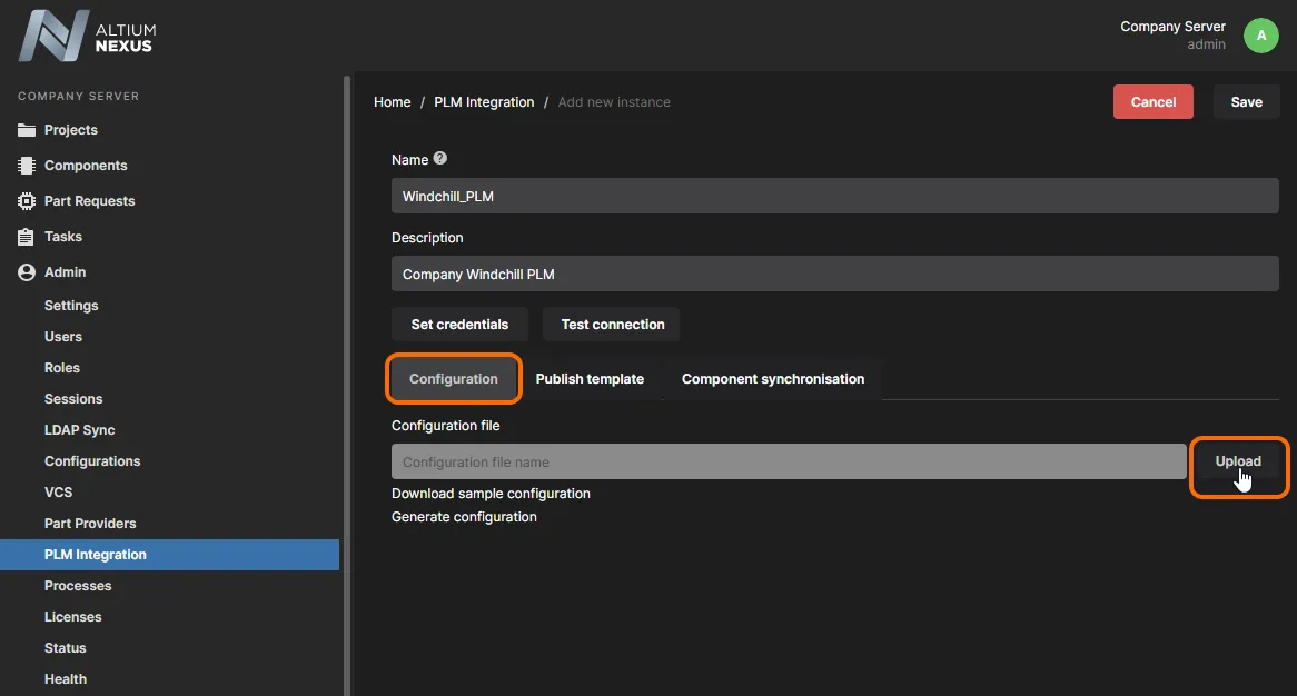
Similarly, a compatible publishing template is added through the  button under the Publish Template tab. In the following Publish Template dialog use the
  button to browse to and select the correct template file.
 Add and configure the interface to your company's PLM system. With a valid connection, you can then publish project release data to the PLM system (using defined process definitions)
in accordance with an active publishing template for the instance, and also schedule synchronization of components between that PLM and the NEXUS server.
The setup files for the Agile and Arena PLM instances also support the formalized Change Order workflow, which is enabled in the Publishing Template file and configured in the Configuration file.
The capability on the NEXUS side for a PLM instance is enabled in the XML Publishing Template through a ProjectChangeOrder Declaration entry, while a set of publishing rules in a PublishRules entry are used to define how the data will be processed when pushed to the PLM side. Within the XML Configuration file, the Change Order is configured in an Entity of the type ProjectChangeOrder (and plmType: Engineering Change Order). See example .
.
When a NEXUS publishing process such as Publish with PLM is run, the NEXUS process workflow will offer the option of instigating a Change Order workflow, using an existing Change Order or not using a Change Order at all – as specified in the XML configuration file. Note that subsequent PLM updates to the project will require a Change Order.
Rather than using the supplied configuration files to create a new enterprise system instance, the Workspace's internal configuration generator may be used to create a custom configuration that derives its structure from the server's data model. The generator requests connection information (PLM type and URL), and then interrogates the NEXUS server for registered component types (Capacitors, Diodes, etc) and their matching Component Templates to construct a base configuration file – click on the following expanding section for more information:
Configuration Generator
A custom configuration feature is available from the Generate configuration link on the Add new instance page, opened from the  button in the Workspace.
In the Generate Configuration dialog select the type of enterprise system that will be connected to – either one of the available PLM types (Windchill etc) or a Custom type – then its remote URL. Select the  button to create a new
 dm-configuration.xml file that may then be saved and then added to the new PLM instance from the  button.

The generator creates the configuration to match the data model of the current NEXUS server installation, so for example, Component Types that are registered in the server are added as entity types in the configuration file (dm-configuration.xml). Each entity section has matching ToPlm and ToAltium sections and mapped parameters sourced from the matching component template (if available). Also included are project publishing sections to map the release package elements to the enterprise system.
All sections in the generated configuration include TODO comments that highlight areas to add or change for compatibility with your server/PLM configuration. For more information on editing the configuration file to work with your server/PLM setup, see the explanatory comments included in the supplied sample configuration files.
A method of testing or confirming how PLM component data will be imported into the NEXUS server is to use the
CSV Import tool, which transfers component data from a comma-delimited CSV file to the server under the control of its XML configuration file. Both the configuration file and source CSV file can be edited as needed for testing purposes.
When a configuration file has been edited and then re-uploaded to the PLM instance, make sure that you test (validate) the connection to detect any problems that may have been introduced – see below.
Connection Validation
The NEXUS Workspace offers a comprehensive PLM Instance connection validation check, which is available from the  button in the Add/Edit Instance page. This will perform a range of configuration compatibility checks and immediately report the results.
When the connection validation report is run, the Workspace analyses the current configuration and publishing template settings for compatibility with both the NEXUS server and target enterprise system data. Configuration issues such as path errors, unmatched component type definitions and parameters, invalid Lifecycle or Revision settings are detected and reported in the following Configuration Validation Report dialog.

If configuration errors are reported – resulting in an overall ERROR status (Status) – these will need to be addressed before the new instance can be created. A WARNING status, which indicates issues such as NEXUS server components types that are not included in the configuration, or specified attributes that are not available on the enterprise system side, allows the configured instance to be saved and used.
The reported errors and warnings may be then corrected in the applied configuration/publishing files, and/or by making changes in the settings of the Workspace or enterprise system. Be sure to click the  button once your instance is defined successfully. That instance will appear in the current listing of connected instances, back on the main PLM Integration page of the interface.
When a configuration file has been edited and then re-uploaded to the new instance, use the

button again to detect any problems that may have been introduced.
Component Synchronization
Synchronization of components between the Altium NEXUS server and the connected enterprise system instance – or to be more specific, their parametric data – is based on the LibSync process workflow. The LibSync process is predefined in the NEXUS Workspace and not accessible (or editable) from the server's Admin - Processes page. However as a workflow based process, the results of its synchronization action may be viewed and any errors handled.
Using the synchronization process involves the following:
- Configuring the synchronization setup for each component type, which in practice is:
- Determining the direction of synchronization (to the server, or to the PLM).
- Determining which component types are involved, and where new components are to be created.
- Configuring the mapping or parameter attributes.
- Configuring the Part Choices data mapping, if applicable.
- Performing the synchronization.
The first two item groups above are handled in the configuration file used for the connected enterprise system instance (such as a PLM). The synchronization itself can be performed on-demand, from the PLM Integration page of the Workspace interface, and/or can be scheduled – automated synchronization at periodic intervals, defined when configuring the connection to the PLM instance.
Configuring Synchronization
Within the configuration file, the connectivity with the enterprise system instance is defined between the Instance tags as a specified Driver type and a target URL. When the Configuration Generator has been used to create the configuration file, the included Driver and URL references are those entered in the Generate Configuration dialog during the generation process.
<Instance>
    <Driver>[Driver Type]</Driver>
    <Url>[PLM API URL]</Url>
</Instance>
- When the Arena® PLM driver is specified in the configuration file, an additional entry is available to accommodate the Arena workspaces that are available for an Arena user account. The optional multi-digit ID reference attribute is added to the
Instance section between context tags, as shown in the below example.
-
<Instance>
    <Driver>Arena</Driver>
    <Url>https://api.arenasolutions.com/v1/</Url>
    <Context>12345678</Context>
    <!-- If a workspace ID is not defined, the PLM instance will work with Arena's default workspace for that account. -->
    <!-- The server will report an error if another PLM synchronization session is attempting to use a second workspace from the Arena user account. -->
</Instance>
- When the connected system is PTC Windchill PLM, it may be necessary to add a configuration line to enable the units of measure for Value readings.
In the following Schema section of the configuration file, you define a section for synchronization mapping for each dedicated part type. On the NEXUS server side, this is the component of type altiumType – its value is one of the type parameters options that can be seen in the Data Management - Component Types page in the NEXUS design client space. On the PLM side, a part is created of type plmType, as determined by its value in the PLM space.
The section is declared as an Entity in the file, an example of which might be, for capacitors:
<Entity altiumType="Capacitor" plmType="Capacitor">
  .
  .
</Entity>
The plmType value may vary, depending on the particular PLM instance you are using.
Within the Entity, two sections are used to control and configure synchronization from the NEXUS server to the PLM instance, and the PLM instance to the server – allowing for uni- or bi-directional synchronization. Use the following sections, in conjunction with the comments available in the sample configuration files, to learn more. Ultimately, what gets defined in the configuration file will vary, depending on your specific needs, and also the (PLM) attributes that have been defined in the connected enterprise system instance.
ToPlm
This section is used to control and configure synchronization from the NEXUS server to the PLM instance in the form:
<ToPlm sync="true">
  .
  .
</ToPlm>
To disable synchronization in this direction, set sync="false".
Within the ToPlm section, the following sections are defined:
- How new components are created in the PLM instance – between the tagset <CreateInfo> and </CreateInfo>. One example might be choosing an item naming scheme defined in the target enterprise system, and specifying an item numbering prefix:
<CreateInfo>
    <Numbering name="Electrical">
        <Fields>
            <Field name="Code" value="120"/>
        </Fields>
    </Numbering>
</CreateInfo>
- Filtering to limit which components in the server are synchronized with the PLM – between the tagset <SourceCriteria> and </SourceCriteria>.
This is essential if you have say, 6000 capacitors in your NEXUS server, but only want a folder of 85 ceramic capacitors to be synchronized. You could specify a particular folder be involved (e.g. with the entry: <Folder>Components/Capacitors/Ceramic</Folder>). You can optionally use other criteria to narrow the filter even more, based on parameter values – all such criteria filters should be joined by AND.
- A listing of attributes (parameters) that should be passed for the components from the server to PLM – between the tagset <Attributes> and </Attributes>. An example of this is:
<Attributes>

<!-- Name/Comment from NEXUS will be passed to PLM field Name 'as is' -->
<common:Attribute>
	<common:Key>name</common:Key>
	<common:Value>${parameter.Name}</common:Value>
</common:Attribute>

<!-- Number generated on PLM side will be propagated to NEXUS -->
<!-- as PlmPartNumber parameter (note: any parameter name can be used)-->
<common:Attribute attributeType="item" primaryKeyOrdinal="1">
	<common:Key>number</common:Key>
	<common:Value>${parameter.PlmPartNumber}</common:Value>
</common:Attribute>

<!-- NEXUS component description will go to PLM field Description. Value will be prefixed with 'Extended' -->
<!-- Description on NEXUS side is a revision level parameter -->
<common:Attribute attributeType="revision">
	<common:Key>description</common:Key>
	<common:Value>Extended ${parameter.Description}</common:Value>
</common:Attribute>

<!-- This attribute will not be pushed to PLM component as part of library synchronization -->
<!-- It is being used to pass values during project publish with BOM -->
<common:Attribute>
    <common:Key>refDes</common:Key>
    <common:Value>${parameter.LogicalDesignator}</common:Value>
</common:Attribute>

<!-- RoHS field in PLM will be set to 'YES' -->
<common:Attribute>
	<common:Key>RoHS</common:Key>
	<common:Value>YES</common:Value>
</common:Attribute>

</Attributes>
- The part number that gets created on the PLM side (PlmPartNumber) is the primary key for linking the components on either side, and will be propagated back to the NEXUS server component.
- Parameters such as component Reference Designators (
refDes) only apply when a project with a BOM document is published, since the designator parameter is not involved in component synchronization.
- Note that there is the notion of Item parameters (attributeType="item"). These parameters, such as the PlmPartNumber parameter above, are added to the parent Component Item in the server and available to its revisions. They do not cause a new revision of a Component Item to be created if their value is changed. This is in contrast with Revision parameters (attributeType="revision"). These parameters, such as the Description parameter above, cause a new revision of a Component Item to be created if their value is changed.
ToAltium
This section is used to control and configure synchronization from the PLM instance to the NEXUS server in the form:
<ToAltium sync="true" mode="createAndUpdate">
  .
  .
</ToAltium>
The optional
mode statement determines how component data is synchronized from the enterprise system to the NEXUS server. The default mode (
createAndUpdate) allows new components to be created in the server and also existing server components to be updated, whereas the alternative
updateExisting mode allows only existing server components to be updated.
To disable synchronization in this direction, set sync="false".
Within the ToAltium section, the following sections are defined:
- How and where new components are created in the NEXUS server – between the tagset <CreateInfo> and </CreateInfo>.
<CreateInfo>
    <!-- <ComponentTemplate>TODO component template Revision ID</ComponentTemplate> -->
    <RevisionNamingScheme>1-Level Revision Scheme</RevisionNamingScheme>
    <LifecycleDefinition>Component Lifecycle</LifecycleDefinition>
    <Folder>Components/Inbox/Capacitors</Folder>
</CreateInfo>
When a component entry is created in the NEXUS server, the Component Template associated with the target server folder (Components/Inbox/Capacitors in the above example) will be used, if one has been specified. This will also define the Item Naming Scheme used for a created component, overruling one that has been specified in the target server folder – conversely, if the folder does not define either a template or a naming scheme, the synchronization will fail.
Also note that in the sample configurations, a default revision naming scheme (1-Level Revision Scheme) and lifecycle definition (Component Lifecycle) are defined to be used – these are overruled if a component template is associated with the target server folder.
A component target folder specified in the configuration file will overrule the Default Folder setting in a Component Template.
If a specific component template reference is added in the configuration (for example; CMPT-00001), this template will be used instead of a template associated with the target server folder. Its settings will overrule any parameter settings in the configuration file (such as the lifecycle definition, etc), with the exception of a defined target Folder.
<CreateInfo>
    <!-- A specified Template overrules other CreateInfo settings, except the target Folder -->
    <ComponentTemplate>CMPT-00001</ComponentTemplate>
    <RevisionNamingScheme>1-Level Revision Scheme</RevisionNamingScheme>
    <LifecycleDefinition>Component Lifecycle</LifecycleDefinition>
    <!-- A specified target Folder overrules that defined in an applied Template -->
    <Folder>Components/Inbox/Capacitors</Folder>
</CreateInfo>
Note that the specified template will apply to newly created server components only. This approach is particularly useful for managing the importation/synchronization of proprietary component parameters from an external system into the NEXUS server. In this case a tailored Component Template can be applied to interpret incoming parameter data, set suitable default values, specify unit data types, and also to specify the Lifecycle Definition and Revision Naming scheme for the newly created server components.
If a parameter is specified with an item attribute type (dynamic) in the configuration file and that parameter exists in the applied Component Template, the component parameter value will not be updated during component synchronization. For that parameter to behave in a 'dynamic' way during component synchronization (where a Value update does not cause a new revision), the parameter reference will need to be removed from the applied Component Template.
- Filtering of data retrieved from the enterprise system (PLM) instance – between the tagset <SourceCriteria> and </SourceCriteria>. A filter statement might restrict the component data received from the PLM to those created by a specific author (as illustrated in the supplied example configuration), or to component items that have a particular attribute Value (Business Unit = Engineering_RD), as shown below).
<SourceCriteria>
    <ns2:Attribute>
        <ns2:Key>Business Unit</ns2:Key>
        <ns2:Value>Engineering_RD</ns2:Value>
    </ns2:Attribute>
</SourceCriteria>
- A listing of attributes (parameters) that should be passed for the components from the PLM to the NEXUS server – between the tagset <Attributes> and </Attributes>. An example of this is:
<Attributes>

<!-- Name field from PLM will be passed to name/comment field in NEXUS -->
<common:Attribute attributeType="revision">
	<common:Key>name</common:Key>
	<common:Value>${attribute.name}</common:Value>
</common:Attribute>

<!-- Description field from PLM will be passed to Description field in NEXUS on revision level -->
<!-- Revision level attributes will cause new revision to be created in case parameter value is changed -->
<common:Attribute attributeType="revision">
	<common:Key>Description</common:Key>
	<common:Value>${attribute.description}</common:Value>
</common:Attribute>

<!-- Number field from PLM will be passed to PlmPartNumber field in NEXUS on revision level  -->
<!-- Note: any attribute name can be used -->
<common:Attribute attributeType="revision" primaryKeyOrdinal="1">
	<common:Key>PlmPartNumber</common:Key>
	<common:Value>${attribute.Number}</common:Value>
</common:Attribute>

<common:Attribute attributeType="item">
	<common:Key>DynamicCONTS</common:Key>
	<common:Value>Will not cause revision update if changed ${attribute.LastModified}</common:Value>
</common:Attribute>

</Attributes>
Note that the part number on the PLM side (PlmPartNumber) is the primary key for linking the components on either side, and is propagated back to the NEXUS server component.
Notice also, that there is the notion of 'dynamic' parameters (attributeType="item"). These parameters, such as the DynamicCONTS parameter above, are Item-level parameters. They are added to the parent Component Item in the server, and available to its revisions. They do not cause a new revision of a Component Item to be created if their value is changed. This is in contrast with 'strong' parameters (attributeType="revision"). These parameters, such as the Description parameter above, are revision-level parameters. They cause a new revision of a Component Item to be created if their value is changed.
The section for defining Part Choices data mapping is found at the end of the sample (or a generated) configuration file.
PartChoices
Along with Entity declarations within the configuration schema is an additional section for defining component Part Choice data mapping between the enterprise system (PLM) and the NEXUS server. The section allows for specific Part Choices attribute parameter mapping for most supported PLM systems, and Approved Manufacturing List (AML) relationships for Aras and Arena PLM systems. This is a bidirectional global definition – that is, for either direction, but not both simultaneously – that specifies the component manufacturer and part number attributes used for the propagation of Part Choices data.
When Part Choices synchronization is enabled in the configuration file (sync="true"), the Value of the specified attributes is transferred to the targeted system. The direction of that data propagation is determined by the 'To' expression, where ToAltium specifies that parametric data from the PLM component is applied to the created/updated NEXUS component, and ToPlm will cause the Part Choices data associated with the NEXUS component to be ported to the PLM side. The enabled configured applies to all defined component entities, so the Part Choice data will be transferred to the specified target whenever a component dataset is encountered.
An example entry for a ToAltium Part Choices mapping in a configuration file – where the PLM system attributes are MFR1 (Manufacturer Name) and MPN1 (Manufacturer Part Number) – might be:
<PartChoices>
    <ToAltium sync="true">
    <MfrMappings>
        <MfrMapping>
            <MfrName>MFR1</MfrName>
            <MfrPartNumber>MPN1</MfrPartNumber>
        </MfrMapping>
    </MfrMappings>
    </ToAltium>
</PartChoices>
Part Choice data synchronization also supports multiple part choice data entries. These additional attributes need to be specified in the configuration file mapping as another pair of attribute definitions, for example: MFR2 and MPN2 as shown below:
<MfrMappings>
    <MfrMapping>
        <MfrName>MFR1</MfrName>
        <MfrPartNumber>MPN1</MfrPartNumber>
    </MfrMapping>
    <MfrMapping>
        <MfrName>MFR2</MfrName>
        <MfrPartNumber>MPN2</MfrPartNumber>
    </MfrMapping>
</MfrMappings>
Enterprise systems that have native/built-in manufacturer part choice functionality, such as Arena PLM, do not require mapped parameters in the configuration file. In this case, the acceptance of Part Choice data is simply enabled in the related configuration section.
<PartChoices>
    <ToAltium sync="true"/>
</PartChoices>
Or when the data transfer direction is to the enterprise system:
<PartChoices>
    <ToPlm sync="true"/>
</PartChoices>
When Part Choice data is imported into a server component item it will not duplicate or replace an existing Part Choice that has been manually entered, and will otherwise be added as a new, additional Part Choice for that component – which will be updated by subsequent synchronization runs.
PTC Windchill PartsLink Support
The PTC Windchill PLM system provides an optional PartsLink module that allows parts to be classified in groups. Part Classifications specified in Windchill also can include associated Attribute/Value pairs to provide further definition within that Classification. The PartsLink system allows specific component types to be targeted easily and quickly and is supported by the NEXUS Workspace's PLM Integration for bidirectional synchronization and read/write access.
In a Workspace configuration instance for Windchill, a PartsLink Classification is created in Windchill by specifying a binding attribute in the ToPLM section in the format as shown in the below example:
<common:Attribute>
	<common:Key>Classification</common:Key>
	<common:Value>102-Capacitor</common:Value>
</common:Attribute>
In the above case, the Key/Value pair defines a Classification named 102-Capacitor. This may have an associated classification Attribute created in Windchill by specifying a name and value parameter (here, Capacitance) – note that multiple Attributes can be applied to a single Classification:
<common:Attribute>
	<common:ClassificationName>102-Capacitor</common:ClassificationName>
	<common:Key>Capacitance</common:Key>
	<common:Value>${parameter.Value}</common:Value>
</common:Attribute>
In the configuration's ToAltium synchronization section, the data sourced from Windchill can be filtered for a desired part Classification within the <SourceCritera> tagset by specifying its ClassificationName.
<SourceCriteria>
	<ClassificationName>102-Capacitor</ClassificationName>
</SourceCriteria>
To source all parts that comply with a matching Classification Attribute value (say, all 10uF Capacitors), the <SourceCriteria> section should include configuration attribute settings that define a ClassificationName and its associated classification Attribute key and Value.
<SourceCriteria>
	<common:Attribute>
		<common:ClassificationName>102-Capacitor</common:ClassificationName>
		<common:Key>Capacitance</common:Key>
		<common:Value>10uF</common:Value>
	</common:Attribute>
</SourceCriteria>
To extract a specific Classification Attribute value from Windchill, source the Value parameter from the specific Attribute name associated with a ClassificationName.
<common:Attribute attributeType="revision">
	<common:ClassificationName>102-Capacitor</common:ClassificationName>
	<common:Key>Value</common:Key>
	<common:Value>${attribute.Capacitance}</common:Value>
</common:Attribute>
Within Windchill itself, a PartsLink Classification is defined by creating a binding attribute that can be applied to a part type. A part Classification Attribute is then added to a defined Classification class.

Component entries in Windchill will incorporate their defined Classification and any specified Classification Attribute parameters, which are in turn are available to the NEXUS PLM component sync process.

When a component entry is synchronized from Windchill to the server and PartsLink interaction has been specified in the server's PLM configuration, Windchill's Configuration Attributes for that part will propagate to Altium NEXUS.

PTC Windchill SSO Support
The ability to use Single Sign On (SSO) authorization when connecting to a Windchill PLM system is also available and is set up through the NEXUS Workspace interface. This provides a simplified and secure connection authorization method when performing NEXUS PLM processes such as Project Creation and Publish to PLM. In practice, the arrangement allows Windchill access to be granted using the OAuth delegation standard via an identity provider service such as PingFederate.
Access to the SSO setup is available under the OAuth tab in the NEXUS Workspace PLM Management page (Admin - PLM Integration), where multiple OAuth provider instances can be added.
 Use the OAuth tab on the PLM Management page to access the OAuth provider setup.
The OAuth provider authorization setup is completed from data available from your configured identity provider. Enter the information required by NEXUS – IDs, tokens, URLs, etc – in the page fields and then save the completed configuration.
 The information required to set up a new SSO OAuth instance is sourced from the existing OAuth provider configuration.
To finish the setup, enable the new OAuth provider instance in the Windchill XML configuration file – see comments in the Windchill sample configuration file for more information.
<Instance>
  <Driver>Windchill</Driver>
  <Url>https://MyWindchill.company.com</Url>
  <OAuthProvider>Windchill-PingFederate</OAuthProvider>
</Instance>
The first time you use the new setup during a NEXUS process such as Publish to PLM, your nominated OAuth provider will open to authorize the connection. Once this validation has been completed, subsequent PLM publishing will not require this step.
- The Parameters, Attributes and Values included in a configuration file are case-sensitive.
- Other than the common inclusion of a primary sync key (such as
PlmPartNumber), it is not recommended to include the same component attribute/parameters in both the ToAltium and ToPlm sections of a configuration file. Bi-directional synchronization occurs in that order (from PLM to Altium first), so the PLM data will always dominate in this situation.
- Refer to the example configuration and publishing files for information on setting up integration with your enterprise system.
Performing Component Synchronization
Component (library) synchronization can be performed as a manual or timed process, from the Sync action button of a PLM instance entry on the Workspace PLM Integration page or as an automated cycle specified in the instance setup, respectively. Click the  control associated with the PLM instance that you wish to synchronize. The synchronization process will proceed through the
 LibSync workflow, in accordance with the settings defined in the associated configuration file.
The control changes to  . If you want to stop the synchronization process, click this control. A confirmation window will appear, where you can click
  to cancel the synchronization – all components already synchronized will remain so, but no further synchronization beyond that point will occur.
 Component synchronization in progress between the NEXUS server and the indicated PLM instance.
Synchronization will involve only those components that have been modified since the last synchronization was run (i.e. their timestamp is later than the last synchronization date), and which pass the synchronization criteria in the configuration file. This is referred to as Incremental Synchronization.
When component synchronization is run, the LibSync process moves through its predefined Workflow until it completes or encounters an error. Refresh the browser (F5) to show the current state of the sync process. To monitor or review the LibSync process, select the Synchronization status tab and choose the Closed listing option – if a process is still running it will show in the Active listing. The  button, available to Administrators, can be used to download a detailed record of all listed synchronization activities in a comma-delimited CSV file format (
Synchronisation status.csv).
The view’s sub-tabs provide the following information:
- Diagram – a graphic representing the process workflow, with its current step position highlighted (Competed or the error/failure state).
- Data – an information summary of the process action, including the success or failure of its steps and a link to the logged process report – see below.
- History – a time log of the main server synchronization events listed in sequence.
The LibSync process results are also available in the Process Management page (Admin » Processes) under the Browser tab.

The details of the selected LibSync event shown under the Data sub-tab includes a link to the system log file (PLM [date-number].log) for the event.
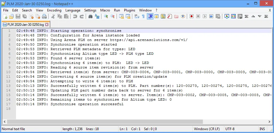
If a LibSync process fails, a Handle errors task is created with associated error data including summary information and process diagram. Current action tasks are available in the Tasks Management page, accessed from the Tasks option on the main menu.
Scheduled Synchronization
You also have the ability to schedule automated synchronization. To do so, edit the PLM instance (from the main PLM Integration page, click on its name, or the associated control), select the Component Synchronisation tab and enable the Synchronize PLM Components with server on schedule option. Use the Synchronize every controls to set up the automated sync schedule as required. The system is very flexible and allows you to:
- Set up scheduled synchronization every 15/30/45/60/75/90 minutes.
- Set up scheduled synchronization every x hours.
- Set up scheduled daily synchronization, to be performed at a nominated time.
The schedule you define will be reflected back on the main PLM Integration page, in the Sync scheduled column.
 Setting up a synchronization schedule.
To set up scheduled synchronization requires you to provide valid user credentials (for your PLM system). The credentials should have already been registered when setting up the PLM instance, but if not, click the

button and enter your
User name and
Password into the subsequent
PLM Credentials window. Without valid credentials, scheduled synchronization will remain in the OFF state. On-demand synchronization will also not be possible.
You can also run the synchronization process on-demand. Click the  button and choose which mode of sync you need:
- Incremental – in this mode, only those components that have been modified since the last synchronization was run (i.e. their timestamp is later than the last synchronization date), and that pass the synchronization criteria in the configuration file, will be included in the sync, with changes propagated accordingly. This is the default mode, and is the same mode that is run by clicking the
 control for a PLM instance on the main PLM Integration page.
- Full – this mode forces a full synchronization. All components that pass the synchronization criteria in the configuration file will be included in the sync, with changes propagated accordingly.
Process Workflows
The following process definitions (and underlying workflows) are available through the NEXUS Workspace, in support of PLM integration:
These process definitions cannot be activated and used as is. Each of these is therefore more like a 'template' – edit to suit your company's requirements, name, and save as a new process definition, which you can then activate and use, along with all other definitions in the respective process theme.
- Part Requests process theme:
- Part Request with PLM Part Create – supporting the automatic creation of a Component in your PLM instance, and then propagation of the generated part number back to the component in NEXUS. The workflow diagram is shown below.
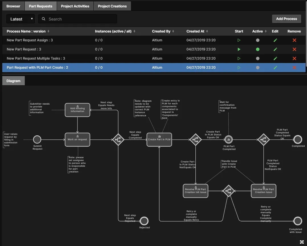
One important thing to note is that when you modify this sample definition to create your own, you must specify the PLM instance into which parts are to be created. Select the Create Part in PLM entity in the workflow diagram and choose the PLM instance from the drop-down menu associated with the PLM Instance field. This menu lists all currently defined PLM instances (as defined on the PLM Integration page of the interface).

► See Creating and Managing Processes for more information on working with process workflows.
- Project Activities process theme:
- Publish to PLM (User selects) – publish of released managed project outputs to the integrated PLM instance, where the user is able to select exactly which outputs get published. The workflow diagram is shown below.
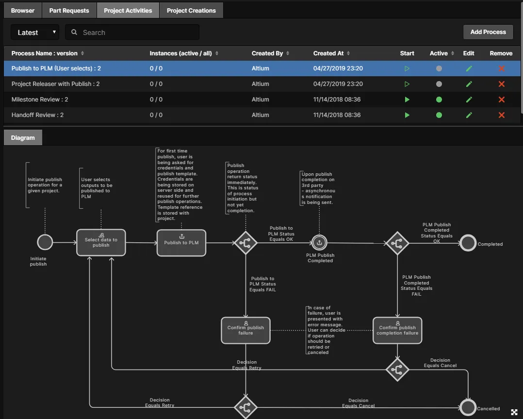
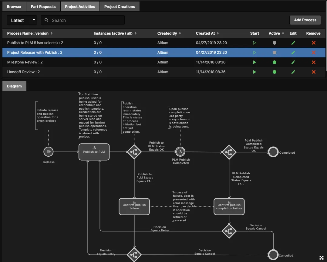
- Project Releaser with Publish – publish to the integrated PLM instance as an additional stage of the Project Releaser. The workflow diagram is shown below.
- Project Creations process theme:
- Project with initialise in PLM – supporting the automatic creation of part numbers in your PLM instance, and then propagation of these as Parameters of the NEXUS design project. The workflow diagram is shown below.

Accessing PLM-related Processes
The following sections highlight where to access activated PLM-related processes. And since the samples cannot be used directly as supplied, the following were created from them for the purpose of illustration:
- PR with PLM Part Create – created from the sample process definition: Part Request with PLM Part Create.
- Publish to Company PLM – Choose Data – created from the sample process definition: Publish to PLM (User selects).
- Project Releaser with Publish to Company PLM – created from the sample process definition: Project Releaser with Publish.
- Create Project with PLM Initialise – created from the sample process definition: Project with Initialise in PLM.
Note that NEXUS Workspace Administrators can start a new instance of any activated process definition – directly from the corresponding process theme tab within the
Processes area of the Workspace interface – by clicking the

control.
Part Requests
Access from within the Altium NEXUS client from the Explorer panel, after having conducted a search, from within the Details pane of the Manufacturer Part Search panel, or from the link at the bottom of the component listing in the Components panel.
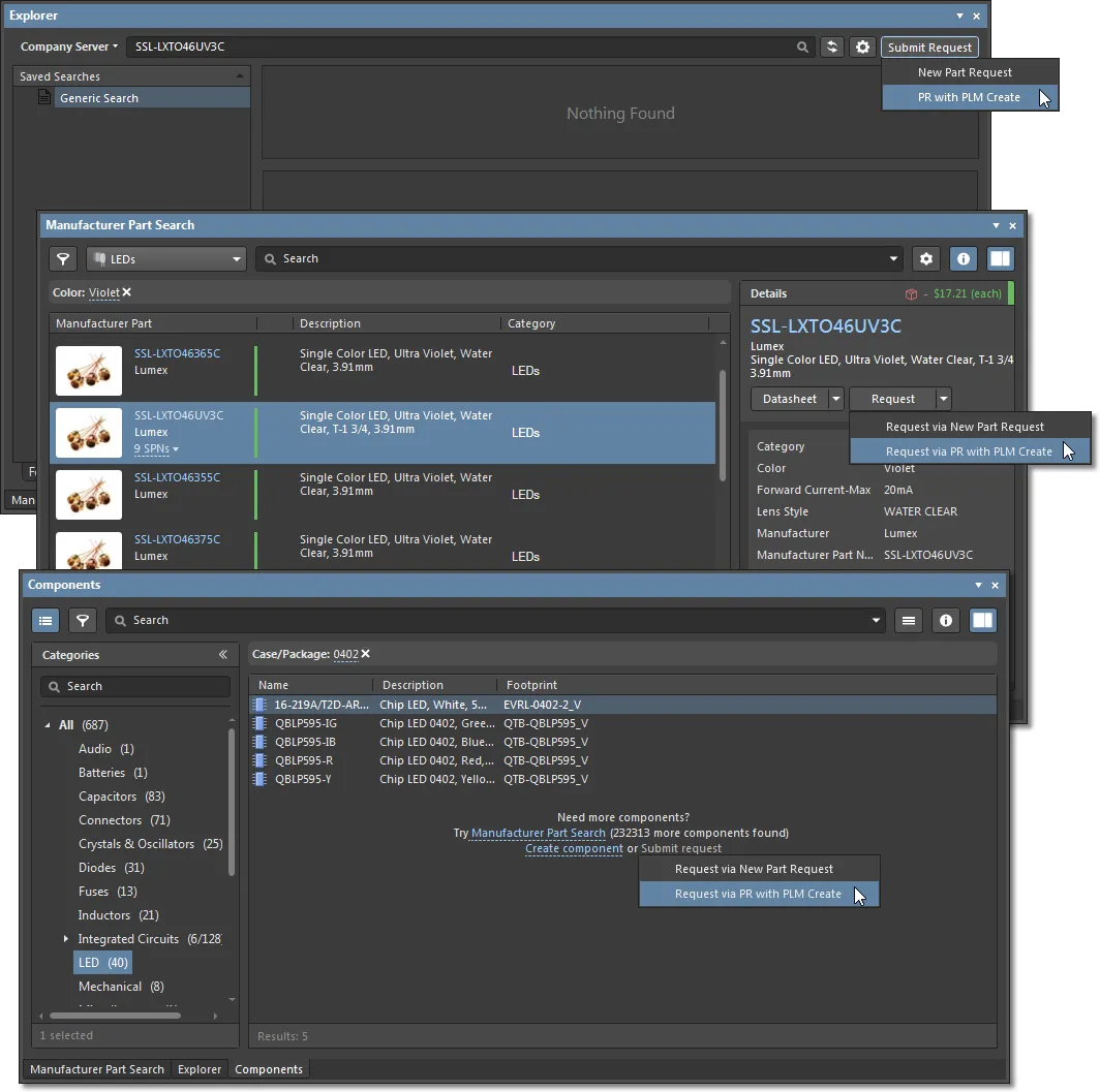
From the NEXUS Workspace interface, the activated process definition can be accessed from the Part Requests page, by clicking the  button at the top-right of the page.

Part Request Example
The following example shows briefly the creation of a new part in the NEXUS server, followed by the automatic creation of a corresponding part in the PLM instance. The generated part number is then propagated from the PLM instance back to the component in the server, as an Item parameter – meaning that a new revision of the NEXUS component is not needed to be released. For this example, the process definition being used is PR with PLM Part Create – derived from the sample definition Part Request with PLM Part Create.
The information provided here will be similar for the different supported PLM systems. What will vary will be the configuration file that you may change to suit your company needs, and also if you have modified the workflow for the process definition used to create the part.
- Start the Part Request process, and fill out the subsequent form – detailing the initial request – as required. In the image below, the request is being submitted through the Part Requests page of the NEXUS Workspace interface, and a single part is being requested.

- The new part request will be shown as an active process on the Part Requests page, with its current state reflected in the main entry, and also in the diagram for its underlying workflow.

- Once the required user has taken (or has been assigned) the task to work on the request, they ultimately create the requested part(s). Each component created (and/or chosen) to satisfy the request is added to the Components field of the task. The added components will automatically be created in the PLM. In the image below, a single component – CMP-007-00038 – has been created and added. Ensure that the Next step field is set to Completed and click the
 button.

You may be requested to provide login credentials for the PLM system specified in the Part Request process workflow.

- The process workflow will continue, with the specified component created in the PLM instance. Once the process has run to completion, you can see the generated PLM part number on the processes' Data tab. Be sure to switch the filter (top left) to viewing Closed processes.

Administrators can use the

button to download a detailed record of all listed Part Requests in a comma-delimited CSV format.
- Back in the NEXUS design client, browse to the created component in the Explorer panel, and switch to its Preview tab view. In the parameters region, notice that an additional parameter has been added – PlmPartNumber – whose value is the number for the corresponding created part in the PLM.
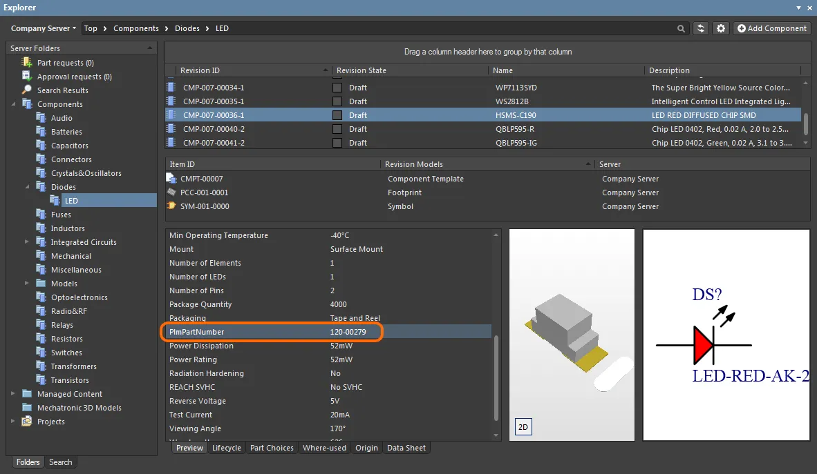
Note that the parameter has been added to the component, but its revision remains the same – there was no re-releasing of the component. This is because the parameter is an Item-level parameter – added to the Component Item itself, and available in all of its revisions.
Project Activities
Project Design data released from the NEXUS design client to the NEXUS server can be propagated to PLM in a controlled way with the server's Publish to PLM processes. The NEXUS processes define the interface and methodology for the publish activity, and the specified XML Publishing Template defines how the file data is propagated to the target PLM system.
Publishing Folder Support for Windchill PLM
When configuring a Publish to PLM process for Windchill® PLM, you can also specify (and create) a target Windchill folder for documents published from the NEXUS server.
The related Windchill folder parameters are defined in the Publishing Template XML file that is applied to your Windchill PLM integration entry in the NEXUS Workspace. Folder definition nodes are in the tag format <pt:Folder>xxx</pt:Folder> – where pt is the current namespace and xxx is the full folder path – and are placed as a publishing rule within the FileDistribution section for each document type (such as a PCB.zip Fabrication output for example).
An example of the Publishing XML structure hierarchy would be:
<pt:EntityRule id="FAB">
  <pt:FileDistributions>
    <pt:FileDistribution archiveName="PCB.zip">
      <pt:Folder>PRODUCT/Projects/${project.name}/FAB data</pt:Folder>
The last entry line would specify (or create) a publishing target folder for the PCB.zip Fabrication output with the Windchill folder structure (where the project's name is MyProject):
PRODUCT
  Projects
    MyProject
      FAB data
Note that the folder path defined in the Publishing XML file is absolute (rather than relative), and can include other project properties such as the project Name (${project.name}) and Assembly Number (${project.PLM_ASSEMBLY_NUMBER}).
Also note that capability to create a target folder is supported for Windchill REST API services 1.3 and higher. For older REST versions the specified target folder path must exist, but cannot be created.
Standard Publishing Process
On the design side, the standard publish to PLM process can be accessed from within the Altium design client NEXUS from the Project » Project Activities sub-menu for the active project.

Project related processes are also accessible from the
Project Activities context sub-menu, accessed by right-clicking on the entry for the design project in the
Projects panel.
From the NEXUS Workspace interface, the active process definitions can be accessed from the Project Management view by clicking the  button.
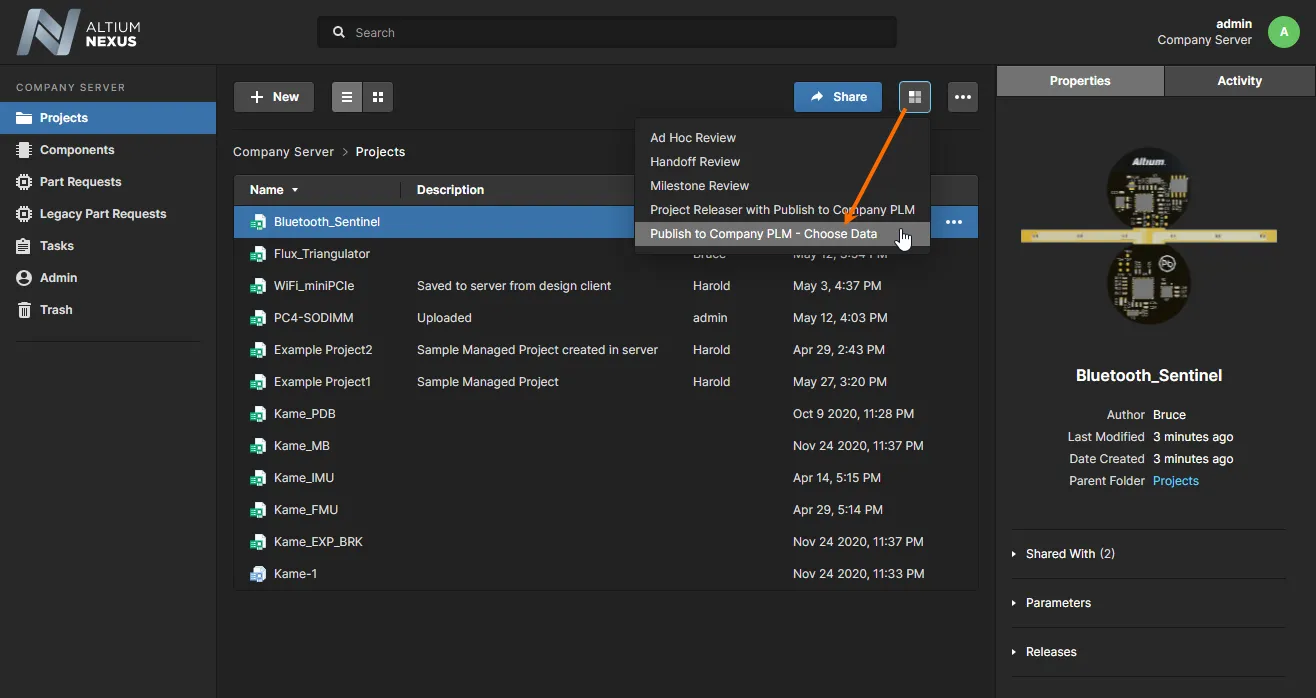
Publishing with the Project Releaser
The process for publishing to a PLM instance as part of the Project Releaser can be accessed from within the NEXUS design client from the Project » Project Releaser sub-menu for the active project.
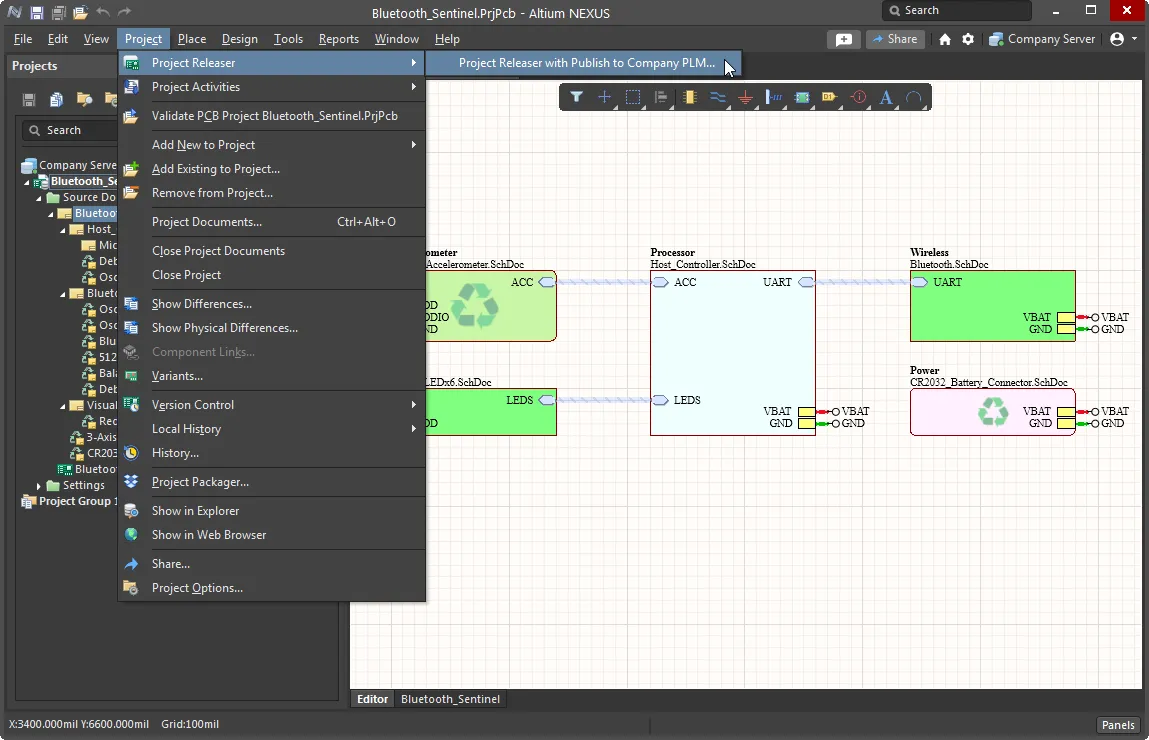
Release related processes are also accessible from the
Project Releaser context sub-menu, accessed by right-clicking on the entry for the design project in the
Projects panel.
The Project Releaser will appear, with an additional stage – 7: Publish to PLM. In addition, a command is available from the menu associated with the  button – Prepare & Release & Publish to PLM – should you wish to run the Project Releaser without stopping to review the generated data, and execution report.
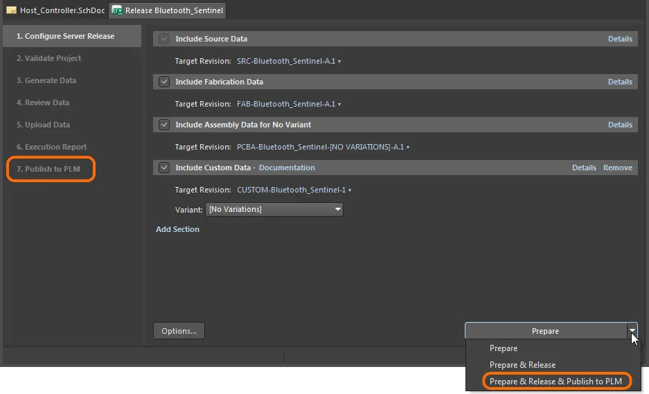
Defining the Stage Name
If you are using the sample process definition – Project Releaser with Publish – to create your own definition, the stage name presented on the design client side is Publish to PLM by default. The composite command on the Project Releaser  button dropdown menu also incorporates this name: Prepare & Release & Publish to PLM.
However, you have the ability to change how this (and the description tip associated with the stage) is presented to users. The fields to do this are available in the underlying workflow for the process, when the Start element (of type Start Release) is selected. These fields are:
- Action name – the name of the post project release action, which is the name of the stage presented as stage 7 in the Project Releaser. An entry for this field is mandatory if there are tasks defined in the process workflow. This name will also be used for the menu command, in the format Prepare & Release & <Action name>.
- Action description – description of the post project release action, which is presented to the user in the Project Releaser as the tool tip for the stage 7 entry.
 Default settings for the Start element in a workflow based on the sample process definition Project Releaser with Publish, and the presentation in the Project Releaser.
The following image shows these fields changed in the underlying workflow, and the resulting impact on the entries in the Project Releaser.
 Changed settings for the Start element when used in a workflow to publish to PLM through the Project Releaser.
If you run the Project Releaser with the standard Prepare command, after reviewing and releasing the data, the  button will be presented at the Execution Report stage. Click this to continue the underlying workflow for the process, to publish to the PLM. The Login Credentials dialog will appear. Enter the Username and Password for your PLM instance, and select the PLM Template you want to use (which appears in the form <PLMInstance>:<PublishingTemplate>).
If you chose to use the
Prepare & Release & Publish to PLM command, you will ultimately be presented with the
Login Credentials dialog directly. The
Project Releaser will not pause at the
Execution Report stage, and no

button will be presented.
Note that your PLM instance login credentials are only required for the first time you publish to that instance. These will then be stored with the NEXUS server Workspace. After that, any publishing of that project to that same PLM instance will proceed directly, in accordance with the defined workflow and chosen publishing template.
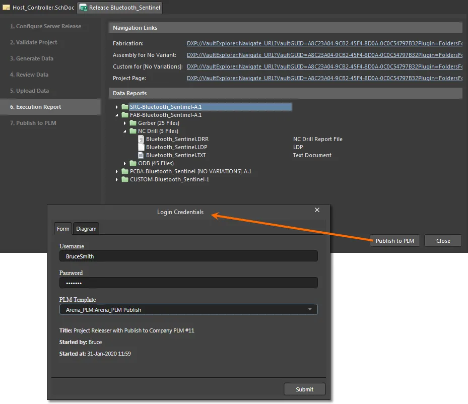
Click on the Diagram tab to see the underlying workflow for the process.

Click the  button to proceed with the publishing process, in accordance with that workflow.
If you're publishing for the first time and part numbers (on the PLM side) are not yet associated with the managed project, those part numbers will be created in the PLM and associated with the project as part of that initial publication. You also have the ability to define component entries for NEXUS components in the PLM instance, as part of the publishing operation – to get a BOM of components within the PLM (optional, based on the publishing template defined and used when publishing the project to the PLM instance).
Check the status of the publish to PLM process through the Workspace interface by selecting the Activities view from within that project's detailed view -- when the project has been opened from the Projects view. Select the Opened view option to see the status while the process is running, and the Closed activities option to access status information when the process has completed.

You can see exactly what has been created, such as part numbers in the PLM instance, under the process workflow's Data tab.
Project Creations
On the design side, access from within Altium NEXUS design client from the main File » New » Project in <server> sub-menu.
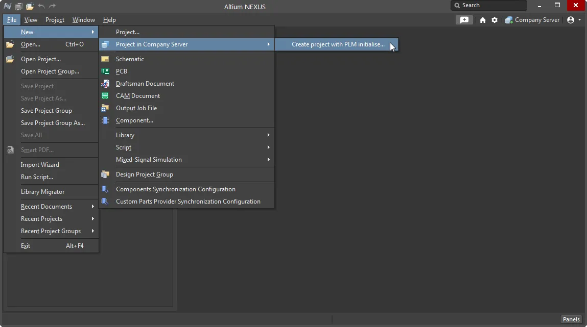
From the Altium NEXUS Workspace interface, the activated process definition can be accessed from the Projects view by clicking the  button.
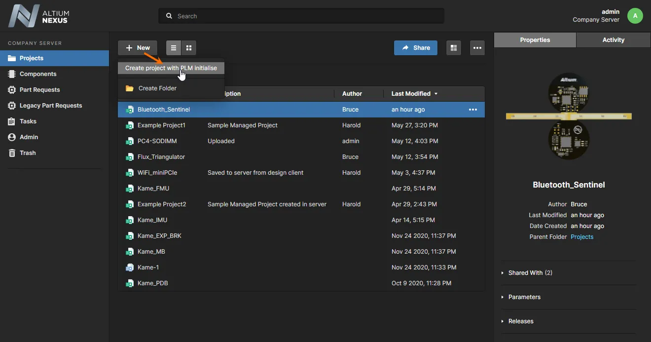
And also when Cloning a project, accessed from the  menu button in the Projects view.

The process workflow will proceed, with a dialog to enable you to define the project, in terms of its name, description, type, and any Project Template Item that should be used in its creation. After clicking Start, the Login Credentials dialog will appear. Enter the Username and Password for your PLM instance, and select the PLM Template you want to use (which appears in the form <PLMInstance>:<PublishingTemplate>). Then click Submit to proceed with the workflow.
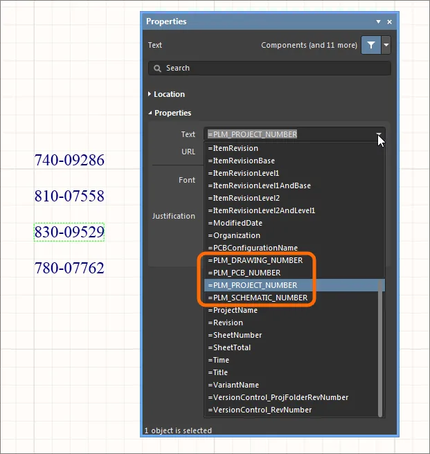
The relevant part numbers will be automatically created for the project in your PLM instance, and then propagated back to the server as NEXUS project parameters. These parameters will be available to use as special strings – access from the
Properties panel with a placed text string selected in the design editor. Server parameters defined for the project can also be viewed on the
Server Parameters tab of the
Project Options dialog (
Project » Project Options).
Project Creation Example
The following example shows briefly the creation of a new project, with initialization in the PLM. The process is invoked from the Altium NEXUS design client using the Create Project with PLM Initialise definition – derived from the sample definition Project with Initialise in PLM.
The information provided here will be similar for the different supported PLM systems. What will vary will be the configuration file and publishing templates that you may change to suit your company needs, how the target PLM is configured, and also if you have modified the workflow for the process definition used to create the project.
- After launching the process (File » New » Project in <server> » Create Project with PLM Initialise) a dialog appears (named after the process definition) with which to define the project. For this example, we'll just call the project Example_Project_with_PLM_Init, give it a description, and leave all other fields – including those on the Advanced tab – unchanged.
- With the project defined, click the
 button. The Login Credentials dialog appears. Since this is a new project, you need to supply your PLM login credentials, and nominate the PLM instance and associated publishing template to be used. The example here uses a Configuration file and associated Publishing Template (as requested) for an Arena PLM.

With the credentials supplied and PLM instance and publishing template chosen, click the  button.
- The process will proceed to completion (assuming no errors occur) as can be seen in the Tasklist panel, under the closed Activities listing – check the Show closed option from the associated
 button menu. Select the Activity entry for more information about the completed process and its data set.
Note that The Data tab provides relevant data including the part numbers created for the various project entities. The PLM part numbers correspond to the Items created in PLM that will be populated with release data when the project is published to PLM -- such as when a Project Releaser with Publish (to PLM) process is run.

The completed process and its related information can also be viewed in the NEXUS Workspace interface by selecting the Activities view from within that project's detailed view -- when the project has been opened from the Projects view. Select the Closed activities option (top right) to access status information for the completed process.

- Within the Altium NEXUS design client, the new project is apparent in the Projects panel, scheduled for commit to the Git-based Versioned Storage design repository in the NEXUS server – right-click on project entry and use the Save to server command to do so. You can then add source documents and design away. When you come to publish, the project is already linked to the relevant parts in the PLM instance.

From the Server Parameters tab of the Project Options dialog, or under the project's Parameters listing in the Explorer panel, you can see the part numbers assigned in the PLM instance that relate to the relevant project entities that can be released/published.

How the PLM parameter names relate to project release packages is specified in the PLM configuration file, which in turn is determined by the name and numbering attributes required by the PLM system.
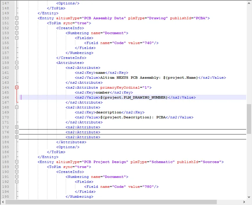
When you place a Schematic text string, the PLM parameters associated with the project will be available as special strings:
