PCB 3D Circuit Design Software Helps You Build Advanced Products

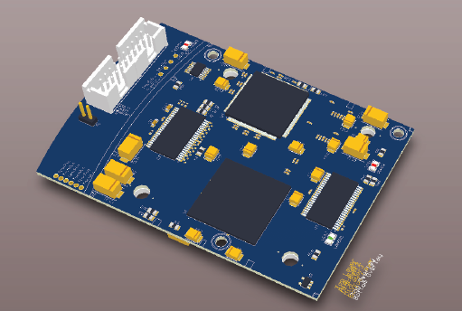
New products are intimately designed to fit their enclosures, and getting the design right takes the right set of PCB design tools. When you can see your entire board, you can spot layout errors and component collisions and make sure your new circuit board will fit inside its enclosure easily. Now you can design and evaluate all aspects of your circuit board layout when you use the native MCAD tools in Altium Designer’s complete PCB design platform.
ALTIUM DESIGNER
PCB 3D design software to help you prepare your circuit board for manufacturing and assembly processes.
Designing electronics in the late 1990s or early 2000s was a very different experience than it is today. Older designs often weren’t limited in terms of board space, and mechanical constraints weren’t as difficult to satisfy for most products. As 3D electronic circuit design software components got smaller, their enclosures became more intricate. Today, it’s essential to investigate the mechanical aspects of a PCB alongside its electrical behavior.
Instead of working out the mechanical details of your circuit board with multiple CAD programs and prototypes, you need a design platform that allows 2D and 3D PCB design software in a single interface. Altium Designer is the only PCB 3D design software application that includes a complete set of electrical design tools and integrates with popular MCAD applications like SolidWorks. You can design more advanced PCB design software products with sleek enclosures when you use Altium Designer.
3D Board Design Software Gives You a Better View
In the past, electrical engineers were forced to devise their own methods for avoiding board-to-board and component-to-component interference. 3D board design rule checks (DRC) were often accomplished using Visio Drawings of the tallest component outlines, converted to Millars, which were then compared manually.
Design schedules have become compressed over time, and new products have much more advanced feature sets. In addition, creating meaningful user experiences demands a sleek enclosure that cleanly fits around your board and components. PCB 3D design software is the best way to ensure your circuit board layout and components satisfy your mechanical constraints as you create your PCB.
View and Check Your Design in 3D
Checking your design in 3D is all about verifying clearances, tolerances, and fit to your enclosure. If your circuit board passes your basic measurement checks, your mechanical team can then do a 3D analysis to ensure that none of the components interfere with any mechanical elements, other components, or other PCBs.
Working with a rules-driven design platform like Altium Designer helps automate these tasks within your printed circuit board design tools. Rather than exporting to a different application to check clearances and animate your board, you can complete these tasks quickly with the 3D PCB software layout features in Altium Designer.
- Modern designers need MCAD and ECAD design features to get a new product correct. Your MCAD design tools should be accessible alongside your standard circuit board design features.
- When your MCAD tools instantly import your layout into a 3D view, you can quickly check component clearances fit your enclosure.
- You can use the IPC-Compliant footprint wizard in Altium Designer for 2D and 3D CAD models for your components. You can then export the resulting CAD models or instantly place your PCB footprint into your PCB layout.

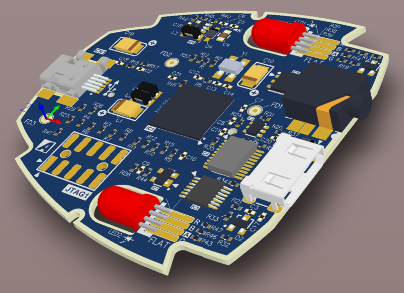
Model the board in 3D within Altium Designer
Working with 3D Board Design Tools
The best time to look at your PCB layout in 3D is after you’ve placed your components, designed your layer stack, and defined board regions. After you place footprints in your PCB, you can view the board in 3D within Altium Designer to ensure it appears as expected and will fit in its enclosure. You can then start routing signal traces after you’ve verified multiple boards fit together as designed and your rigid-flex board will bend as you need.
When you start using MCAD features for PCB design, you can instantly get a view of your circuit board before you complete your PCB layout. MCAD tools make use of STEP files to view your board in 3D and to model more advanced boards, such as multi-board assemblies and rigid-flex PCBs. You will see in real time where conflicts are and how to best place parts for smart problem resolution. If you like, you can then import your printed circuit board into a popular 3D modeling program for enclosure design and modeling.
Switch Between 2D and 3D for Advanced Circuit Boards
Altium Designer gives you the ability to switch between the normal 2D environment to be able to view and work within a 3D environment. Seeing how your printed circuit board components fit within a 3D board design environment is just the beginning. You don’t have to leave the 3D view to route traces or make component placement adjustments. Simply drag and drop components where you want them, and Altium Designer will update the design in 2D and 3D. You can then access all the other design features you need for advanced PCB design software.
- Altium Designer supports flex and rigid-flex design in 2D and 3D PCB design. You can also export a 3D model of your flex or rigid-flex board in its final orientation.
Learn more about using PCB 3D design software for flex and rigid-flex PCBs.
- The complete set of 3D PCB layout tools in Altium Designer makes multi-board PCB design simple.
Learn more about multi-board design in 3D with Altium Designer.
- The unified set of design tools and native MCAD engine also allows you to view your board in 3D during panelization.

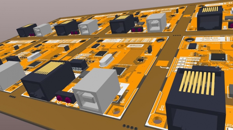
Circuit board panels can be viewed in Altium Designer’s native 3D MCAD environment when preparing your design for PCB fabrication.
Altium Designer Has the MCAD 3D Board Design Tools You Need
Whether you’re designing for aerospace, IoT, or any other application, printed circuit boards are getting smaller and being squeezed into tighter spaces. You shouldn’t need to download multiple tools and simulators to create a 3D view of your PCB layout. The standard 2D CAD features in Altium Designer are ideal for creating a new schematic and PCB layout. The strength of Altium Designer is in its unified interface, where all your design features are accessible in a single program.
Unification in Altium Designer spans all your design tools, making all your design features accessible in a single program. Altium Designer’s intuitive user interface allows you to efficiently work within a PCB 3D environment without the need to switch to other CAD applications. No longer will you have to rely on external mechanical CAD systems to verify your integrated physical design, you can do it all from within Altium Designer.
Build Better Boards with Rules-Driven Design Software
One of the most frustrating things for a PCB designer is to notice they need to change the layout in the middle of routing just to comply with mechanical constraints. The design rules engine in Altium Designer does these checks before you get deep into your layout, helping you avoid redesigns and meet your design schedules. Whether you need to build simply 2-layer boards or complex rigid-flex PCBs, all your design features are accessible in Altium Designer’s unified interface.
- Altium Designer gives you a complete schematic editor and PCB layout features all in the same program. You’ll have control over every aspect of your circuit board when you use Altium Designer.
Learn more about the unified design and manufacturing features of Altium Designer.
- The rules-driven engine in Altium Designer spots constraint and collision violations in 2D and 3D board design, ensuring your new board will be defect-free once it comes off the assembly line.
Learn more about rules-driven PCB design in Altium Designer.
- The 3D MCAD tools in Altium Designer are accessible alongside your standard circuit board design and layout features. You can instantly switch from 2D to 3D for the complex board and enclosure design.

Build high-quality circuit board designs with the native ECAD/MCAD design features in Altium Designer.
PCB 3D circuit design software is much easier when you work in a powerful environment for circuit board design. The rules-driven design environment in Altium Designer ensures your circuit board will fit within its enclosure and spot component collisions as you create your PCB. If you need powerful visualizations of your printed circuit designs, use the best PCB 3D circuit design software on the market: make the switch to Altium Designer.
Altium Designer on Altium 365 delivers an unprecedented amount of integration to the electronics industry until now relegated to the world of software development, allowing designers to work from home and reach unprecedented levels of efficiency.
We have only scratched the surface of what is possible to do with Altium Designer on Altium 365. You can check the product page for a more in-depth feature description or one of the On-Demand Webinars.


