
Synchronizing a Multi-board Assembly
Overview
In mechanical design, the standard approach to developing a product is to build the device from a number of sub-assemblies. Altium's electronic design software supports a similar concept, where multiple PCBs can be brought together to create an assembly of PCBs, in ECAD it is called a Multi-Board Assembly. This assembly can also include the enclosure and other mechanical elements.
 A multi-board assembly open in Altium's ECAD multi-board assembly editor.
The process of assembling the printed circuit boards into the enclosure is best performed in MCAD. However, the ECAD engineer may also need to perform electro-mechanical checks, such as component-to-component and component-to-enclosure clearances; as well as checking the access to and labeling of the human interface elements, such as indicators and displays, buttons, and connectors.
To do this, the mechanical and electrical engineers need to be able to pass the assembly back and forth between MCAD and ECAD. This can be done using Altium MCAD CoDesigner. Synchronizing an assembly of boards between the MCAD and ECAD domains has numerous advantages, including the ability to quickly verify the current state of the assembled device by both the mechanical and electronic design teams.
Workflow
The slides below show a summary of synchronizing a Multi-board assembly between MCAD and ECAD. This order of steps is not fixed, for example, the slides show a sequence where the individual PCBs have been Pulled from ECAD and assembled into the MCAD enclosure, before deciding to transfer the entire assembly to ECAD.


The numbered steps below show the same process but in a different sequence. This time the MCAD device enclosure is linked to the ECAD multi-board assembly first, and then the PCBs are added to the device enclosure.
1. Transfer each PCB from ECAD to MCAD
To transfer the assembly from ECAD to MCAD, you first Push each PCB individually and then Pull them into MCAD, saving each as a mechanical assembly.

| Push from ECAD | Use the MCAD CoDesigner panel to Push each board from ECAD to the Workspace, as shown above. |
| Pull into MCAD | Use the Altium CoDesigner panel to Pull each board from the Workspace, saving each as an MCAD assembly. Note that board-level synchronization must be maintained independently of the synchronization of the assembly that those boards become part of. |
 ).
). ).
).2. Push the ECAD Multi-board Assembly from ECAD
The ECAD multi-board assembly is defined as a Multi-board project, which then has each of the PCB projects added to it.

| Define the assembly in ECAD | In ECAD, boards are added to a multi-board assembly by placing a Module for each board on a Multi-board schematic, and then Importing those boards into a Multi-board assembly document. Learn more about Multi-board design in ECAD. |
| Mating the boards | It is recommended that mates are defined in the MCAD device assembly, rather than in the ECAD multi-board assembly. |
| Push the assembly from ECAD | Once the PCBs have been added into the ECAD multi-board assembly document, the ECAD assembly is ready to be Pushed to MCAD. After positioning and orienting the boards in MCAD, the location and orientation information can then be transferred back to ECAD. |
3. Create the Device Assembly in MCAD and Link the ECAD Multi-board Assembly
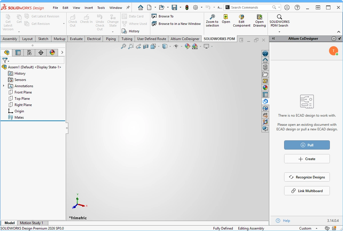
The MCAD device assembly is linked to the ECAD multi-board assembly via the Altium CoDesigner panel. You can link at any stage; from an empty MCAD assembly file, once the enclosure(s) has been added, or after one or more of the boards has been added. In this example, the enclosure has been added, but not the boards.

| Create the MCAD assembly | Create a new device assembly in MCAD. |
| Include the enclosure | If required, add the enclosure to the device assembly, and save the assembly. |
| Recognize Designs button | The Altium CoDesigner panel includes a button labeled Recognize Designs ( |
| Link the MCAD assembly to the ECAD assembly | The MCAD and ECAD assemblies are linked by clicking the Link Multiboard button in the Altium CoDesigner panel, as shown in the image above. If CoDesigner is connected to the same Workspace that the Multi-board Assembly was pushed to, the ECAD MBA will be listed in the Select Project from Company Workspace dialog ( |
 ).
). )
) ).
). ).
).4. Pull the Multi-board Assembly into MCAD
Now that the MCAD and ECAD assemblies have been linked, the synchronization status can be checked by performing a Pull in MCAD.

| Check for differences | Once the assembly-level link has been established, CoDesigner can check for differences between the MCAD assembly and the ECAD MBA by clicking Pull in the Altium CoDesigner panel ( |
| Changes highlighted in yellow | Since the PCBs are present in the ECAD assembly but not in the MCAD assembly, the PCBs need to be added to the MCAD assembly. A change highlighted in yellow indicates that CoDesigner cannot complete this change without assistance. Hover the cursor over the Change to display a tooltip, with information about how to resolve the problem, as shown in the image above. |
| Adding the boards in MCAD | The first time the assembly is Pulled, CoDesigner will not know where to source the MCAD versions of the PCBs from. To locate each board for CoDesigner, click the Location ellipsis button ( |
| Changes highlighted in red | When a change is highlighted in red, it indicates that it cannot be applied and that CoDesigner cannot assist in resolving it. An example would be when a PCB in the assembly has not yet been pushed from ECAD. |
 ).
).5. Working with the MCAD Device Assembly
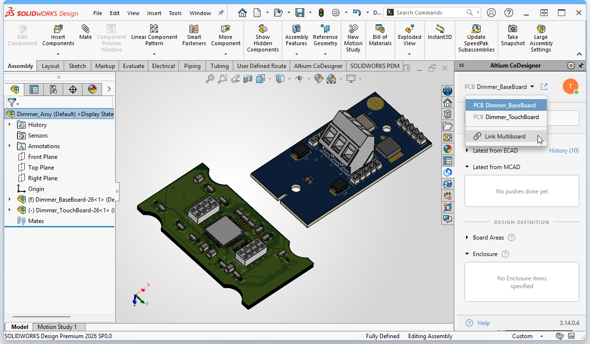
The MCAD assembly now includes multiple items that can be synchronized between MCAD and ECAD, including each of the PCBs, and also the entire assembly. To allow you to perform CoDesign functions, such as: define enclosure objects, synchronize changes made to a specific board within the assembly, or synchronize changes made to the location of a board in the assembly, you must indicate to MCAD CoDesigner which PCB or assembly is currently being worked on.
This is done by selecting the PCB or assembly in the dropdown menu at the top of the Altium CoDesigner panel, as shown in the image below.

| What is being synchronized | You choose what you would like CoDesigner to synchronize with ECAD in the dropdown at the top of the Altium CoDesigner panel, as shown in the image above. For example, if you need to edit one of the PCBs, select it in the dropdown, perform the edits, and then Push those board changes to the ECAD PCB in the usual way ( |
 ).
).6. Define the Enclosure in MCAD
Any number of MCAD objects can be defined as being part of the enclosure to MCAD CoDesigner.

| 1. Select the objects | Select the enclosure objects in the MCAD model tree. |
| 2. Define as enclosure | Click the Enclosure button on the Altium CoDesigner ribbon, this tells CoDesigner that the selected object(s) are part of the enclosure. |
| 3. CoDesigner confirmation | MCAD CoDesigner will confirm that these objects have been identified as being part of the enclosure for the active PCB/assembly. |
| 4. Enclosure objects | The mechanical objects that MCAD CoDesigner recognizes as belonging to the enclosure. These objects will be transferred to the ECAD board/assembly when the design is Pushed to ECAD. Objects can be selected and deleted from the list if required. |
7. Prepare the Device Assembly and Push to ECAD
The enclosure and board objects are oriented and located in MCAD, using the standard techniques. At any stage of this process, the assembly can be pushed to ECAD.

| 1. Prepare the MCAD assembly | Position and mate the PCBs within the enclosure. |
| 2. Select what is being synchronized | Ensure that the Multiboard assembly is selected as the active item in the dropdown at the top of the Altium CoDesigner panel. |
| 3. Push the assembly to ECAD | Push the entire Assembly from MCAD to the Workspace, ready to be Pulled into ECAD. |
8. Pull the Assembly into ECAD
The changes made in the MCAD assembly can be synchronized in ECAD. Open the Multi-board assembly project in Altium Designer, and enable the MCAD CoDesigner panel.

| Check for changes in ECAD | A notification will appear in the MCAD CoDesigner panel, warning that changes have been detected ( |
| Review the list of Changes | Changes will include location updates to the PCBs, as well as the enclosure if it has been added in MCAD. The types of changes that are supported include: PCB location and orientation, addition or removal of enclosure elements. |
| Apply the Changes | Changes can be selectively applied, turn off any that you do not want to apply in this pass. |
| Modify a child PCB | If MCAD design changes have been made to a child PCB in the assembly, those updates must be Pulled into the child PCB project first (from within the ECAD PCB file). The PCB must then be updated in the ECAD multi-board assembly ( |
| Adding a PCB in MCAD | If an additional board has been added to the assembly in MCAD, when you attempt to Push from MCAD a CoDesigner message dialog will appear, warning that the additional PCB is not part of the ECAD multi-board assembly ( ). In this situation you must add that board to the Multi-board assembly in ECAD and then Push the project from ECAD to the Workspace. It is not necessary to Pull this update into MCAD, just Push the assembly from MCAD again and the additional board location and orientation information will be sent to the Workspace, ready to Pull into ECAD. ). In this situation you must add that board to the Multi-board assembly in ECAD and then Push the project from ECAD to the Workspace. It is not necessary to Pull this update into MCAD, just Push the assembly from MCAD again and the additional board location and orientation information will be sent to the Workspace, ready to Pull into ECAD. |
 ).
). ).
).
9. The Assembly ready for the ECAD Engineer
Any required ECAD tasks can now be performed, such as clearance checking and visual confirmation of the fit of the PCBs. The image below shows a section view of the Multi-board assembly in ECAD.
