Configuration and Customization Overview
There are many ways you can configure Altium Designer so that it works the best for you, including using dual monitors, viewing all documents simultaneously, and saving your unique desktop layout.
The Altium Designer design space can be customized in order to help you be more productive in your design work. Resources are the menu bars, toolbars and the shortcut key tables. Behind each resource item, there is a pre-packaged process launcher that activates a command when its resource item is selected. All the commands available from the menus can be added to or deleted from these resources. The pre-packaged process launchers bundle together the process that runs when the command is selected, plus any parameters, bitmaps (icons), captions (the name of an item that displays on a resource), descriptions, and associated shortcut keys. If a process launcher is modified, every linked instance of the command on any bar will be updated.
Configuring the Design Environment
The following sections describe ways you can configure Altium Designer to suit your needs.
Dual Monitor Support
Altium Designer supports the use of dual monitors with a recommended resolution of 2560 x 1440. With many documents open simultaneously, several panels, toolbars and support documents, this feature affords you enough space to configure a more comfortable working environment. You might, for example, dedicate the use of one monitor solely for design, while arranging various panels and additional documents on the other. Use the computer settings to configure your monitor set up according to your needs.
Desktop Layouts
As a further aid in setting up the design environment, Altium Designer supports the notion of Desktop Layouts. This feature allows you to arrange the application's document windows, panels and toolbars around the desktop as required and then save that layout to a file. Using this feature, multiple users can quickly arrange the design space to suit their design habits by loading their preferred layout. Options for saving and loading layouts, including resetting to the default layout shipped with the software, are available from the System - View page of the Preferences dialog.

Customizing Menus and Toolbars
Every designer has a different way of working. Altium Designer recognizes this and, therefore, allows you to customize your design space, which allows you to be more productive. For example, you can create new toolbars and commands, as well as add commands to a toolbar or menu, and also create drop-down menus.
You can easily customize Altium Designer by arranging the menus and toolbars anywhere on your monitors to suit your needs. The key element to customization of your design space is the Customizing Editor dialog, which is used to customize the resources in an editor, as well as adding to or deleting from these resources. When the Customizing Editor dialog is open, you can click and drag commands between the active menus and toolbars. The dialog can be accessed using one of the following ways.
-
Right-click on a menu bar or toolbar then choosing Customize from the drop-down menu;
-
Double-click in a blank area (away from any commands) of a menu bar or toolbar;
-
Choose the View » Toolbars » Customize command from the main menus;
-
From certain editors (e.g., Schematic, Schematic Symbol, PCB, PCB Footprint, Output Job), the command can also be accessed by pressing B to access the Toolbar pop-up and choosing the Customize entry.
Each editor has its own version of the dialog as shown in the example images below.
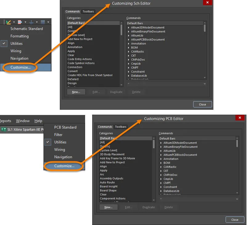
Accessing the Customizing Editor dialog: top image - Utilities toolbar access from a schematic; bottom image - main menu bar access from a PCB.
Behind each resource item, such as a toolbar icon or menu item, there is a pre-packaged process launcher that activates a command when its resource item is selected. The pre-packaged process launchers bundle together the process that runs when the command is selected, plus any parameters, bitmaps (icons), captions (the name of an item that displays on a resource), descriptions and associated shortcut keys. If a process launcher is modified, every linked instance of the command on any bar will be updated.
Customizations are stored in the file \Users\<ProfileName>\AppData\Roaming\Altium\Altium Designer <Solution> <GUID>\DXP.rcs (for a default installation of the software).
Adding a Command to a Menu or Toolbar
A command can be linked or duplicated when it is added to a bar. A linked command will be updated if the original process launcher is modified. A duplicated command, however, will remain as a copy of the original process launcher and not be updated. Duplicated commands can be modified to create a new command by changing its process launcher properties. To add a command to a bar, use the following steps.
-
Right-click on a menu bar or a toolbar then select Customize from the menu. The appropriate Customizing Editor dialog opens.

-
The Categories on the Commands tab of the dialog are the menu and submenu headings sorted alphabetically. By default, the built-in bars (the default menus and toolbars) are displayed in the Commands list. Click on a category to display all the commands associated with that menu bar. These are all the commands that are installed for the selected category.
-
Select the command you want to add to a toolbar or menu from the Commands region on the Commands tab of the Customizing Editor dialog.
-
With the dialog still open, go to the menu or toolbar that you want to add the command to and right-click to display the Customize drop-down menu.
-
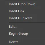
Choose Insert Link to link to the original process launcher or Insert Duplicate to create a copy of the command.
-
Release the mouse button and the command will be added to the menu or toolbar.
Creating a New Command
Use the following steps to create a new command:
-
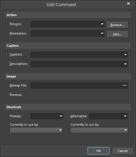
On the Commands tab of the Customizing Editor dialog, click New to open the Edit Command dialog.
-
Click the Browse button to open the Process Browser dialog to select the desired process for the new command.

The Process Browser dialog
Options and Controls of the Process Browser Dialog
-
Filter - enter text to filter the process shown in the List Region.
-
List region - lists the processes used in the software. Click on a process to select it.
-
Show processes - use the drop-down to view and select a specific area of processes to be shown in the List Region. Select All to show all process.
-
Description - displays a short description of the selected process.
-
Use the controls of the Process Browser dialog to search for and find the required process then click OK to return to the Edit Command dialog.
-
In the Edit Command dialog, the Caption will become the name of the command on the appropriate menu, therefore, use a name that is easily recognizable as a new command. An accelerator key can be specified as part of the command's caption by adding the ampersand (&) character immediately before the letter that you want to use as the accelerator.
-
If you require an image to be associated with the new process launcher, click  in the Bitmap File field to find a bitmap file. This image (or icon) will display when the new command is added to toolbars, e.g., the Zoom In command uses the Zoomin.bmp bitmap found in the \System\Buttons folder of the installation.
-
If desired, you can use the Shortcuts region to add a Primary and Alternative shortcut by using the drop-downs for each. Once you have defined the new command, click OK.
-
A [Custom] category will have been added to the Categories region of the Customizing Editor dialog. When selected, the new command is displayed in the Commands region.
-
You can now add the new command to the relevant bar(s). See the Adding a Command to a Menu or Toolbar section for details.
Duplicating Commands
It is often easier to create a new command by duplicating an existing command that is similar then modify its parameters. To duplicate a command, use the following steps.
-
On the Commands tab of the Customizing Editor dialog, select the command you want to duplicate then click Duplicate to create a new copy of the selected command.
-
Click on [Custom] in the Categories region to see the new (duplicated) command in the Commands list.
-
Select the new (duplicated) command then click Edit (or double-click the command) to open the Edit Command dialog in which you can modify its properties (e.g., add a new parameter and a new caption) then click OK.
-
You can select then drag the new command onto a toolbar or menu.
Deleting a Custom Command
You can delete one instance or all instances of a custom command from menus or toolbars. Note that the default commands cannot be deleted.
Deleting a customized command stored in the Custom category will delete all instances of the custom command from all resources.
-
In the Customizing Editor dialog, click on the [Custom] category then select the command you want to delete in the Commands region.
-
Click Delete. All instances of the command will be removed from the bars.

Delete a Command from One Resource
If you want to delete just one instance of a command without affecting other instances:
-
With the Customizing Editor dialog open, at the top of the design space, select the command that you want to delete from the menu or toolbar. A white box around the command indicates it is selected.
-
Right-click then select Delete. Alternatively, click and hold on the menu item or toolbar icon and drag it off its bar. The cursor changes to  while dragging.
Creating a New Toolbar
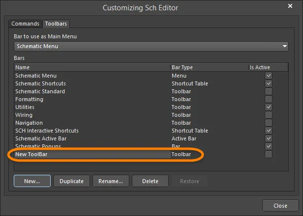
From the Toolbars tab of the Customizing Editor dialog, you can select which main menu and toolbars to display, create a new or duplicate toolbar, as well as rename, delete or restore toolbars. To create a new toolbar, use the following steps.
-
In the Customizing Editor dialog, click the Toolbars tab.
-
Click New to create a new toolbar. New Toolbar appears in the Bars region.
-
With New Toolbar selected, click Rename then enter the desired name for the new toolbar.
-
Activate the toolbar by enabling its associated Is Active box. A blank toolbar will appear docked in the menu area of the screen.
-
You can now add commands to your new toolbar. See the Adding a Command to a Menu or Toolbar section for details.
Duplicating a Toolbar
If you want to create a new toolbar based on an existing toolbar, it is easier to duplicate the original toolbar and edit the commands.
-
On the Toolbars tab of the Customizing Editor dialog, click the Duplicate button to create a new instance of the selected toolbar.
-
Copy of <toolbar name appears in the Bars region.

-
With Copy of <toolbar name selected, click Rename then enter the desired name for the duplicate toolbar.
-
You can now add commands to your new toolbar. See the Adding a Command to a Menu or Toolbar section for details.
Activating Toolbars
Toolbars will only appear on the screen if they are active. Select which toolbars are active (displayed) on the Toolbars tab on the Customizing Editor dialog. When the Is Active box is enabled (checked), the associated toolbar is active and will be displayed.
Alternatively, in the design space (when the Customizing Editor dialog is not open), position the cursor over a toolbar or menu, right-click then select from the drop-down the toolbar you want to activate .
Shortcuts to Adding Commands to Existing Toolbars
With the Customizing Editor dialog open, select the command in a menu or toolbar you want to duplicate or link. Use Ctrl+Click then drag the command to the new location (to Insert Duplicate); use Shift+Ctrl+Click then drag the command to the new location (to Insert Link).
Setting the Main Menu
You can nominate which main menu bar is active (displayed) by selecting a menu from the Bar to use as Main Menu drop-down on the Toolbars tab in the Customizing Editor dialog.

Restoring Menu and Toolbar Defaults
Use the following steps to restore the original default menus and toolbars and delete all customizations.
-
On the Toolbars tab in the Customizing Editor dialog in the Bars region, select the bar you want to restore then click the Restore button.
The Restore button is available only if there have been customizations created for the selected bar.
-
Click OK to confirm the removal of all customizations from the selected bar and restore the original default menus and toolbars.
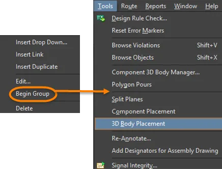
Adding a Group Separator to a Drop-down Menu
You can add a line separator above the item in a menu or before an icon in a toolbar. With the Customizing Editor dialog open, right-click on a menu or toolbar item then select Begin Group.
Creating a New Drop-Down Menu
-
With the Customizing Editor dialog open, place the cursor where you want to add the new drop-down menu. A drop-down menu can be added to create a new main menu, or to create a sub-menu within an existing menu. To create a main menu, select the existing menu to the right of where you want the new menu to appear. To create a sub-menu, select the command on the existing menu below where you want the new sub-menu to appear.
-
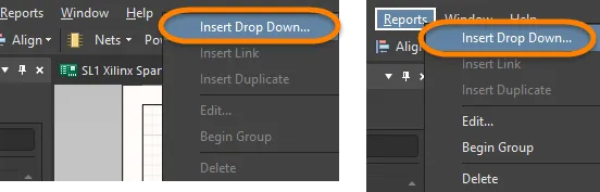
With the cursor positioned, right-click and choose the Insert Drop Down command from the context menu.
-
The Edit Drop Down Menu dialog opens.

-
Enter a Caption (the menu name), a popup key to quickly access the menu (this is optional), and a bitmap for an icon (if required) then click OK. The new menu name (Caption) appears in the menus.
An accelerator key can be specified as part of the menu's caption by adding the ampersand (&) character immediately before the letter that you want to use as the accelerator.
-
You can now add commands to your new menu. See the Adding a Command to a Menu or Toolbar section for details.
Location of Customization Files
The files for your customizations are stored at: \Users\<ProfileName>\AppData\Roaming\Altium\Altium Designer <Solution> <GUID>. These files are:
System-level Commands
On the Commands tab of the Customizing Editor dialog, [System Level] includes the commands to 'toggle floating panel visibility' and to 'toggle floating panel focus'. Any new commands added to this category will become system commands and their shortcut keys can be used in any editor.
Working with Shortcut Key Tables
A shortcut key table lists all the shortcuts currently available in an editor. Only one shortcut key table can be active per editor. As an example, Schematic Shortcuts is the name of the default shortcut key table for the Schematic editor. If a shortcut key is changed in a command, it is updated in the active table automatically.
Shortcut key tables can be added, created, deleted, or modified in the same way as menus and toolbars.
Localization for Foreign Languages
Altium Designer supports several non-English language modes. All menu items and most dialog text will be presented in the language chosen in Windows for the computer on which Altium Designer is installed. Localization is configured on the System - General page of the Preferences dialog. After changing any of the Localization settings, you will need to restart Altium Designer.

