
Preparing Fabrication Data
A wide range of PCB design fabrication file formats is available for both individual and output job file generation, including:
-
Gerber RS-274X and Gerber X2
-
ODB++
-
IPC-2581
-
NC Drill
-
Board Stack Report
-
Printed-based outputs: Composite Drill Drawings, Drill Drawing/Guides, Final Artwork Prints, Power-Plane Prints, Solder/Paste Mask Prints.
-
Fabrication Testpoint Report
Fabrication outputs can be added to the active Output Job file from the menu of the [Add New Fabrication Output] control in the Fabrication Outputs region of the file or from the Edit » Add Fabrication Outputs sub-menus of the main menus.

Generating Gerber Fabrication Data
Each file of the Gerber RS274X format (also known as Extended Gerber, or GerberX) corresponds to one layer in the physical board – the component overlay, top signal layer, bottom signal layer, the solder masking layers, etc. This file format includes aperture definitions, XY coordinate locations for draw and flash commands, and other information needed for PCB fabrication.
Gerber X2 is a direct, and much advanced, evolution of the Gerber RS-274X standard and adds a large range of additional data for PCB fabrication and assembly. Compared to the RS-274X standard, the Gerber X2 format includes critical information, such as layer stack definitions and pad and via attributes. A prime advantage of the Gerber X2 format is backward compatibility with the old Gerber RS-274X standard. Being a multi-file standard, a target fab/assembly house that has not moved to the new standard can extract the traditional Gerber file elements as needed. This may be a significant advantage for those unwilling to tackle a major shift in fabrication file formats, or for fabrication houses with inflexible equipment and software.
The overall benefit of adopting the Gerber X2 format for transferring board design data to fabrication and assembly houses is the rich set of manufacturing data included in the file set and the backward compatibility to the previous standard for a low-risk upgrade path. With a full implementation at both ends of the CAD-CAM chain, the risks associated with data misinterpretation, file errors and variable data interpretation can be largely eliminated. In short, the Gerber X2 and IPC-2581 formats represent a new generation of board design to manufacture data transfer.
With a project PCB file as the active document, the Gerber file set can be generated by selecting File » Fabrication Outputs » Gerber Files or File » Fabrication Outputs » Gerber X2 Files from the main menus. This opens an appropriate Gerber Setup or Gerber X2 Setup dialog in which you can define the plot layers and general configuration applied during the export process. See the collapsible sections below for detailed information on options and controls provided by these dialogs.

Gerber Setup and Gerber X2 Setup dialogs
Output is generated in the location defined in the Output Path field on the Options tab of the Project Options dialog. Generated file names will include the name of the PCB document.
The generated Gerber output is also opened as a composite CAM document that can be edited and/or saved into the current project and managed via the CAMtastic panel.
Options and Controls of the Gerber Setup Dialog

The Gerber Setup dialog. Hover the mouse over the image to alternate between the Layers to plot and Advanced tabs.
Units
Use this region to choose the units used in the generated file:
-
Inches – enable this option to use imperial units where all work is done in mils (1 mil = 1/1000 inch).
-
Millimeters – enable this option to use metric units where all work is done in millimeters.
Decimal
Use the drop-down in this region to specify the numerical precision of the plot coordinates in the Gerber file.
Outputs: FileName.Extension
Use this region to choose the naming option for Gerber files to be generated:
-
*.gbr – enable this option to generate layers with unique filenames but with the same single extension (.gbr).
-
filename.* (gtl, gbl, gto,...) – enable this option to generate layers with the same filename but with different extensions (.gtl, .gbl, .gto,...).
Others
-
Include unconnected mid-layer pads – enable this option to allow unconnected pads in the mid-layer on Gerber plots.
-
Generate Reports – enable this option to generate the following files:
.REP,.EXTREP,.apr, and.APR_LIB. -
Merge regions and pads inside Footprint – enable this option to merge regions and pads within a footprint while generating Gerber outputs.
Layers to Plot Tab
This tab allows you to configure which layers to plot in the Gerber output for the current PCB document.
-
Layers List – a listing of layers in the current PCB available for output to Gerber. Layers are grouped by type (Copper Layers, Silkscreen, Solder Mask, Paste Mask, Mechanical Layers, etc.). Each layer is presented in terms of the following:
-
File Name – the individual Gerber output file name. Naming is based on the project name, layer, and function, and uses an underscore character as a descriptive separator. Click on a layer name to type in a new name if required.
-
Layer Name – the layer name that applies to the output file as defined by the board’s layer stack.
-
Plot – enable this option to include a Gerber plot for that layer or layer group in the generated output. Disable to exclude the plot from being generated for that layer.
-
Mirror – enable this option for a layer or layer group if you want a mirrored Gerber file to be created.
-
-
Plot Layers – use the drop-down to access a menu of commands that allow the Plot field for all layers in the Layers to plot region to be enabled or disabled:
- Select All – select to check all boxes in the Plot column (Gerber data will be created for all checked layers).
- Deselect All – select to clear all checked boxes in the Plot column (no Gerber data will be created).
- Select Used – select to check all boxes in the Plot column of the listed layers that are used in the design.
-
Edit Group – click to open the Add Mechanical Layers dialog in which you can select the mechanical layers that are added to all plot layers in the selected layer group. You can also click the
 button associated with a layer group to access the Add Mechanical Layers dialog.
-
Mirror Layers – use the drop-down to access a menu of commands that allow the Mirror field for all layers in the Layers to plot region to be enabled or disabled:
- Select All – select to check all boxes in the Mirror column (Gerber data will be created for all checked layers).
- Deselect All – select to clear all checked boxes in the Mirror column (no Gerber data will be created).
- Select Used – select to check all boxes in the Mirror column of the listed layers that are used in the design.


Advanced Tab
Aperture Matching Tolerances
- Plus – use this box to define the positive tolerance for aperture matching.
- Minus – use this box to define the negative tolerance for aperture matching.
Leading/Trailing Zeroes
- Keep leading and trailing zeroes – if this option is enabled, all leading and trailing zeroes will appear in the generated Gerber file.
- Suppress leading zeroes – if this option is enabled, no leading zeroes will appear in the generated Gerber file.
- Suppress trailing zeroes – if this option is enabled, no trailing zeroes will appear in the generated Gerber file.
Plotter Type
- Unsorted (raster) – select to use raster machine (default).
- Sorted (vector) – select to use vector machine.
Others
- Optimize change location commands – when this option is enabled, X or Y location data is not included if it does not change from one object to the next.
- G54 on aperture change – check this option to rotate the aperture wheel of the plotter after each aperture change.
- Use software arcs – check this option to use software arcs.
- Use polygons for octagonal pads – check this option to use polygons for any octagonal pads.
-
Generate DRC Rules export file (.RUL) – check this option to generate a DRC Rules Export file (
.RUL). This file report details the design rules for the source PCB document from which the Gerber data is generated.
Legacy Tab

The Legacy tab of the Gerber Setup dialog
Film Size
- X(horizontal) – enter a value for the film length.
- Y(vertical) – enter a value for the film width.
- Border size – enter a value for the border size of the film.
Position on Film
Use the following options to choose the position on the film:
- Reference to absolute origin
- Reference to relative origin
- Center on film
Batch Mode
- Separate file per layer – select this option if you want each layer to generate a separate Gerber file.
- Panelize layers – select this option if you want only one Gerber file to be generated in the format of panelization.
Apertures
- Embedded apertures (RS274X) – when this option is enabled, the apertures are embedded in the Gerber files according to the RS274X standard and all information for each layer is contained in a single file. Enabling this ensures that the current apertures list includes all the required apertures. If this option is disabled, additional controls in this region become available.
- Maximum aperture size – input the maximum size of the apertures for the design.
- Generate relief shapes – check this option to create relief style apertures.
- Flash pad shapes – check this option to flash the pad shapes.
- Flash all fills – check this option to flash all fills.
- Apertures List – lists all the current aperture data.
-
New – use the drop-down to access a menu of commands that allow adding a new aperture and save or load the aperture list to/from an aperture file:
- Add Aperture – select to open the Edit Aperture dialog in which you can specify the properties of the new aperture.
- Load – select to open a dialog with which you can select the location of the aperture file to load.
- Save – select to save the current apertures in the apertures list.
-
Edit – use the drop-down to access a menu of commands that allow editing of a selected aperture or the apertures list:
- Edit Aperture – select to edit the properties of the selected aperture in the Edit Aperture dialog.
- Rename Aperture – select to edit the properties of the selected aperture in the Edit Aperture dialog.
- Clear All – select to clear all apertures from the apertures list.
- Create List from PCB – select to create the apertures list from the current PCB design.
-
 – select to delete the selected aperture.
 Edit Aperture dialog
Notes about Apertures
Unless your PCB manufacturer does not support embedded apertures, it is highly recommended that you use the Embedded apertures (RS274X) option. Most modern photoplotters are raster plotters that can accept any size aperture. Generally, they also accept Gerber files with embedded apertures.
If your manufacturer does not use embedded apertures, a separate aperture file (*.apt) must be included with the Gerber files. If you use an existing aperture file rather than a generated one, the PCB Editor scans the primitives (tracks, pads, etc.) in the PCB document and matches these with aperture descriptions in the loaded *.apt file. If there is no exact match of aperture to primitive, the PCB Editor will automatically paint the primitive with a suitable smaller aperture. If there is no aperture suitable with which to paint, a *.MAT (match) file will be generated listing the missing apertures and Gerber file generation will be aborted.
Options and Controls of the Gerber X2 Setup Dialog

The Gerber X2 Setup dialog. Hover the mouse over the image to alternate between the Layers to plot and Advanced tabs.
Units
Use this region to choose the units used in the generated file:
- Inches – enable this option to use imperial units where all work is done in mils (1 mil = 1/1000 inch).
- Millimeters – enable this option to use metric units where all work is done in millimeters.
Decimal
Use the drop-down in this region to specify the numerical precision of the plot coordinates in the Gerber file.
Outputs: FileName.Extension
Use this region to choose the naming option for Gerber files to be generated:
- *.gbr – enable this option to generate layers with unique filenames but with the same single extension (.gbr).
- filename.* (gtl, gbl, gto,...) – enable this option to generate layers with the same filename but with different extensions (.gtl, .gbl, .gto,...).
Others
- Include unconnected mid-layer pads – enable this option to allow unconnected pads in the mid-layer on Gerber plots.
-
Generate Reports – enable this option to generate the following files:
.REP,.EXTREP,.apr, and.APR_LIB. - Merge regions and pads inside Footprint – enable this option to merge regions and pads within a footprint during generation of Gerber outputs.
Layers to plot Tab
This tab allows you to configure which layers to plot in the Gerber X2 output for the current PCB document.
-
Layers List – a listing of layers in the current PCB available for output to Gerber. Layers are grouped by their types (Board Outline, Copper Layers, Silkscreen, Solder Mask, Paste Mask, Mechanical Layers, Drills, etc.). Each layer is presented in terms of the following:
- File Name – the individual Gerber output file name. Naming is based on the project name, layer, and function, and uses an underscore character as a descriptive separator. Click on a layer name to type in a new name if required.
- Layer Name – the layer name that applies to the output file as defined by the board’s layer stack.
- Plot – enable this option to include a Gerber plot for that layer or layer group in the generated output. Disable to exclude the plot from being generated for that layer.
-
Plot Layers – use the drop-down to access a menu of commands that allow the Plot field for all layers in the Layers to Plot region to be enabled or disabled:
- Select All – select to check all boxes in the Plot column (Gerber data will be created for all checked layers).
- Deselect All – select to clear all checked boxes in the Plot column (no Gerber data will be created).
- Select Used – select to check all boxes in the Plot column of the listed layers that are used in the design.
-
Edit Group – click to open the Add Mechanical Layers dialog in which you can select the mechanical layers that are added to all plot layers in the selected layer group. You can also click the button associated with a layer group to access the Add Mechanical Layers dialog.

Advanced Tab
Aperture Tolerances
Use the options in this region to set the tolerance range used when matching apertures for each item in the plots.
- Plus – use to define the positive tolerance for aperture matching.
- Minus – use to define the negative tolerance for aperture matching.
Plotter Type
Use this region to specify the target photo-plotter type:
- Unsorted (raster) – select to use raster machine (default).
- Sorted (vector) – select to use vector machine.
Gerber X2 Specific
-
File Subject – use this field to select the file type, which is included as a
Partattribute in the Gerber X2 outputs. The drop-down list provides the following choices:-
None -
Autodetect– automatically assigns an attribute from the below list based on the type of board file. For example, a PCB document containing a single board design will be assigned theSinglepart attribute. -
Single– a single PCB. -
CustomerPanel– a board array or shipping panel. -
ProductionPanel– a working panel or fabrication panel. -
Coupon– a coupon (performance test board associated with a main board design). -
Other– none of the above. In the file, a string appended to the attribute informally indicates the part.
-
- File Comment – enter a comment that will be included as an attribute in the generated outputs.
Others
- Optimize change location commands – when this option is enabled, X or Y location data is not included if it does not change from one object to the next.
- Generate DRC Rules export file (.RUL) – enable this option to generate a DRC Rules Export file. The report details the design rules defined for the source PCB document from which the Gerber data is being generated.
Generating ODB++ Fabrication Data
ODB++ is a CAD-to-CAM data exchange format used in the design and manufacture of printed circuit boards. The format was originally developed by Valor Computerized Systems, Ltd., as an open database that could provide a more information-rich data exchange between PCB design software and Valor CAD-CAM software used by PCB fabricators.
The ODB++ Setup dialog provides controls to completely configure ODB++ file output options. The dialog is accessed in one of the following ways:
-
Using an ODB output generator in an OutputJob Configuration file (
*.OutJob). The output is generated when the configured output generator is run. - In an active PCB document, click File » Fabrication Outputs » ODB++ Files. The output will be generated immediately upon clicking OK in the dialog.

Options and Controls of the ODB++ Setup Dialog
ODB++ Version
Select the ODB++ version in which the generated outputs should be formatted: either v. 8.1 or legacy v. 7.0.
 ).
). ).
). ).
).Units
When the v. 8.1 option is selected as the ODB++ Version, select either Millimeters or Inches to be used as your preferred unit of measurement. When the v. 7.0 option is selected as the ODB++ Version, Inches are selected by default and cannot be changed.
File Options
Check the box next to the file type you wish to utilize for output file generation. Options include uncompressed, .zip, and .tar/.tgz files.
Included Data
-
Include Net List – when enabled, the generated outputs will include the netlist.
-
Neutralize Net Names – when enabled, net names are replaced with
Net_[1-…]in generated outputs. -
Merge Net-Tie Nets – when enabled, if a design contains nets connected by Net-Tie components, these nets will report as distinguished single nets in the netlist. Note that this option is disabled when the Generate shortf: List of Intentional Shorts (Net-Ties) option is enabled.
-
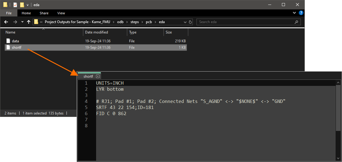
Generate shortf: List of Intentional Shorts (Net-Ties) – when generating ODB++ version 8.1 formatted outputs (v. 8.1 option is selected as the ODB++ Version), enable to generate a
shortffile that contains a list of nets and copper primitives that are intentionally allowed to short ('Net-Ties'). The generated file can be found under theedasub-folder of the step output. Note that this option is disabled when the Merge Net-Tie Nets option is enabled.
-
-
Include Components – when enabled, the generated outputs will include components.
-
Remove Component Properties – when enabled, component properties (parameters) will be removed from the generated outputs.
-
Distinguish different footprints with the same name – when enabled, if one of the footprints with the same name has been modified, only the modified footprint is changed in the output. When the option is not enabled, all footprints with the same name will show as modified in the output.
-
Include Variants Data – when generating ODB++ version 8.1 formatted outputs (v. 8.1 option is selected as the ODB++ Version), enable to include information about all design variants (including
[No Variations]). The following information is included in the outputs when this option is enabled:-
State of each component inside any exported variant (fitted / not fitted).
-
Information about alternate part(s) on the component level for any exported variant.
-
Parameters of each component according to the variation.
-
Custom parameters applied to each variant/component.
When this option is disabled, the output is generated for the variant selected in the Outjob file or, when the output is generated directly from the PCB editor (File » Fabrication Outputs » ODB++), the currently active variant selected in the Projects panel.
-
-
Others
-
Include unconnected mid-layer pads – check to allow unconnected pads in the mid-layer on ODB++ plots.
-
Generate DRC Rules export file (.RUL) – check to generate a
.RULfile that contains all design rules defined for the source document from which the ODB++ data is being generated. -
Export only the objects inside the board outline – check to specify the source that is to be used to create the ODB++ profile layer. The profile layer contains the enclosing boundary of the board. By default, this field is set to Board Outline (also referred to as the board shape, it is a closed polygonal shape that defines the boundary, or extents, of the PCB). Created with each new PCB, this is perhaps the best source for the creation of the Profile layer. If your design has no associated board shape, you can choose which source PCB layer has been used to define the closed polygon representing the boundary of the board (e.g., the KeepOut layer or a specific Mechanical layer). This option is only available when the source document contains an embedded board array object, and it provides control over the extent of objects exported. Note that if an object (e.g., text) is outside of, but touching the board outline and this option is enabled, that object will still be exported.
-
Generate Additional Tools by Drill Symbols – enable to generate additional drill tools based on the defined Drill Symbol groupings. Additional column data will be added where it exists in the Drill Symbols grouping. Existing data columns will not be removed from the generated drill data.
Layers to Plot
Check the box next to each specific layer(s) you want to plot as part of the generated output.

Plot Layers
Use the drop-down, or right-click in the Layers to Plot section, to easily select a group of layers to plot.
-
All On - click to check all boxes in the Plot column (ODB++ data will be created for all checked layers).
-
All Off - click to clear all checked boxes in the Plot column (no ODB++ data will be created).
-
Used On - click to check all boxes in the Plot column of the layers that are used in the project.
-
Edit Group - click to open the Add Mechanical Layers dialog in which you can select the mechanical layers that are added to the selected plot. You can also click
 associated with a layer group or right-click on a layer group then select Edit Group to access the Add Mechanical Layers dialog.
Additional Options
Right-clicking in the Custom Layers section will display:
-
Add Layer - click to add a layer.
-
Edit Layer - click to edit the layer.
-
Delete Layer - click to delete the layer.
Click the layer list cell of a custom layer in the Custom Layers section to open the Select Layer dialog, in which you can select the layers that are added to the selected custom layer.
Generating from an Embedded Board Array
When generating an ODB++ output from a PCB design that contains an embedded board array, the following statements apply:
- The design is analyzed automatically for layer stack violations.
- Embedded boards that are flipped will display their layer stacks as flipped.
- Mid-signal layers and internal planes that are different can still appear on the same mid-layer panel.
- Mid-signal layers and internal planes can be flipped against each other.
When generating ODB++ output from the PCB design, all objects on all layers enabled for plotting will be exported. If you only want to export design objects residing within the board outline, ensure that all additional layers containing objects outside of this boundary are disabled for plotting.
Location of Generated ODB++ Files
The output path for generated files depends on how the output was generated:
- From an OutputJob file - the generated files are stored in a folder within the project folder. The naming and folder structure is defined in the Output Container that the ODB++ output is targeting.
-
Directly from the PCB - the output path is specified in the Project Options - Options dialog. By default, the output path is set to a sub-folder under the folder that contains the Project file and has the name
Project Outputs for <ProjectName>. The output path can be changed as required. If the option to use a separate folder for each output type has been enabled in the Options tab, then the ODB++ files will be written to a further sub-folder namedODB++ Output.
Automatically Opening the Generated ODB++ Output
When generating ODB++ output, you can specify that the output is opened automatically in a new CAM document. The way in which this is accomplished depends on how you are generating the output:
- From an OutputJob file - enable the ODB++ Output auto-load option in the Output Job Options dialog (Tools » Output Job Options from the OutputJob Editor).
- Directly from the PCB - ensure that the Open outputs after compile option is enabled on the Options tab of the Project Options dialog (Project » Project Options).
Generating IPC-2581 Fabrication Data
Related to the existing ODB++ format, IPC-2581 is an open-source standard developed by the Institute for Printed Circuits IPC-2581 Consortium in 2004, but since refined to the most recent Revision A and B releases (IPC-2581A/B).
The standard has progressively gained wider acceptance as an alternative to the traditional fabrication output data composed of, typically, a collection of Gerber, Drill, BOM, and text files, etc. The previous need for a complex mix of fabrication files is due to the inherent limitations of the traditional RS-274x Gerber format, which lacks definitions for the layer stack, drill information, netlist data (electrical connectivity), and BOM information.
The IPC-2581 standard is officially titled ‘Generic Requirements for Printed Board Assembly Products Manufacturing Description Data and Transfer Methodology’ and offers an XML-based single file format that incorporates a rich range of board fabrication data - from layer stackup details though to full pad/routing/component information, and the Bill Of Materials (BOM).
A single IPC-2581 XML file can include:
- Copper image information for etching PCB layers.
- Board layer stack information (including rigid and flexible sections).
- Netlist for bare board and in-circuit testing.
- Components Bill-of-Materials for purchasing and assembly (pick-and-place).
- Fabrication and Assembly notes and parameters.
The potential advantage of adopting the IPC-2581 format for transferring board design data to fabrication and assembly houses is centered on the highly-defined, detailed single file format that is fully understood at both ends of the chain. With a working system of CAD-CAM data exchange established, the risks associated with data misinterpretation, file errors, and variable Gerber interpretation, are largely eliminated. In short, both the IPC-2581 and Gerber X2 formats represent a new generation of board design to manufacture data transfer.
With a project PCB file loaded as the active document, an IPC-2581 file can be generated by selecting File » Fabrication Outputs » IPC-2581 from the main menu. This opens an initial IPC-2581 Configuration dialog in which you can specify the revision of the IPC-2581 standard to be used (A or B), as well as the measurement units and floating point number precision applied during the export process.

Define export settings in the IPC-2581 Configuration dialog.
Options and Controls of the IPC-2581 Configuration Dialog
- IPC2581 version - use the drop-down to select the correct version of IPC-2581.
- Measurement System - use the drop-down to select either Metric or Imperial units.
- Floating Point Precision - type in the desired number or use the arrow keys to select the desired floating point.
- OEMDesignNumberRef - use the drop-down to select the component parameter to be used. DesignItemID is the default.
- Merge Net-Tie Nets - when enabled, if a design contains nets connected by Net-Tie components, these nets will report as distinguished single nets in the netlist.
- Distinguish different footprints with the same name - when enabled, if one of the footprints with the same name has been modified, only the modified footprint is changed in the output. When the option is not enabled, all footprints with the same name will show as modified in the output.
The precision setting determines the positional and sizing accuracy of the data within the generated IPC-2581 compliant file as illustrated in the image below.
 and 6 (right).")
The same section of an IPC-2581 file with the precision set to 2 (left) and 6 (right).
The XML-based IPC-2581 file will be exported to the location defined in the Output Path field on the Options tab of the Project Options dialog. It will be named using the format <PCBDocumentName>.cvg.
Generating NC Drill Fabrication Data
Drill files are used during the board fabrication process to drill holes through the PCB. NC Drill file output options are configured using the NC Drill Setup dialog.

The NC Drill Setup dialog
The NC Drill Setup dialog is accessed in one of the following ways:
- Using an NC Drill output generator in an OutputJob Configuration file (*.OutJob). The output is generated when the configured output generator is run.
- In an active PCB document, click File » Fabrication Outputs » NC Drill Files. The output will be generated immediately upon clicking OK in the dialog.
Options and Controls of the NC Drill Setup Dialog
-
NC Drill Format – use this region to specify the units and format to be used in the NC Drill output files.
-
Units
- Inches – enable this option to use imperial units where all work is done in mils (1/1000 inch).
- Millimeters – enable this option to use metric units where all work is done in millimeters.
-
Format
- 2:3/4:2 – provides a resolution of 1mil/0.01 mm.
- 2:4/4:3 – provides a resolution of 0.1mil/1 μm.
- 2:5/4:4 – provides a resolution of 0.01mil/0.1 μm.
-
Units
-
Leading/Trailing Zeroes – zero suppression is a technique that reduces the size of the generated data files by removing all zeroes from the start (leading) or end (trailing) of numbers.
- Keep leading and trailing zeroes – if this option is enabled, all leading and trailing zeroes will appear in the generated NC Drill file.
- Suppress leading zeroes – if this option is enabled, no leading zeroes will appear in the generated NC Drill file.
- Suppress trailing zeroes – if this option is enabled, no trailing zeroes will appear in the generated NC Drill file.
-
Coordinate Positions
- Reference to absolute origin – use the absolute origin as the reference point.
- Reference to relative origin – use the relative origin as the reference point.
-
Other
-
Optimize change location commands – check this option to optimize any change location commands.
-
Generate separate NC Drill files for plated & non-plated holes – check this option to create separate drill files for plated and unplated holes.
-
Generate separate NC Drill files for VIA features – check this option to create separate drill files for each IPC 4761 via type.
-
Use drilled slot command (G85) – check this option to use multiple drilled holes to create slots.
-
Generate Board Edge Rout Paths – check this option to create a separate NC Rout file to define the board shape, including board cutouts.
-
Rout Tool Dia – specify the tool size used to route the board outline. This option is only available when Generate Board Edge Rout Paths is enabled.
-
-
Generate EIA Binary Drill File (.DRL) – use this option to generate a .DRL file. DRL is a binary format drill file. For a multi-layer PCB that incorporates blind and/or buried vias, a separate drill file for each layer pair is created with a unique file extension.
-
-
Generate Additional Tools by Drill Symbols - enable to generate additional drill tools based on the defined Drill Symbol groupings. Additional column data will be added where it exists in the Drill Symbols grouping. Existing data columns will not be removed from the generated drill data.
Generated NC Drill Files
| Filename | Description |
| FileName.DRL | Binary format drill file. For a multi-layer PCB that incorporates blind and/or buried vias, a separate drill file for each layer pair is created with a unique file extension. |
| FileName.DRR | Drill report – detailing the tool assignments, hole sizes, hole count and tool travel. |
| FileName.TXT | ASCII format drill file. For a multi-layer PCB that incorporates blind and/or buried vias, a separate drill file for each layer pair is created with a unique file extension. |
| FileName-Plated.TXT | ASCII format drill file. Specifically for plated holes in a PCB design. A separate file will be created for each hole type – slotted, square or round. |
| FileName-NonPlated.TXT | ASCII format drill file. Specifically for non-plated holes in a PCB design. A separate file will be created for each hole type – slotted, square or round. |
| FileName-BoardEdgeRout.TXT | ASCII format rout file. Specifically for board outline including board cutouts. |
| FileName.LDP | ASCII format drill pair report. Used by the CAM Editor to detect blind and buried vias. |
Once generated, the output will be added to the project and appear in the Projects panel under the Generated folder in an appropriately-named sub-folder. If you have used a separate folder for each output type, then corresponding (separate) Generated folders will be added to the Projects panel (e.g., Generated (NC Drill Output)).
Location of Generated NC Drill Files
The output path for generated files depends on how the output was generated:
- From an OutputJob file – the generated files are stored in a folder within the project folder. The naming and folder structure is defined in the Output Container that the NC Drill File output is targeting.
- Directly from the PCB – the output path is specified in the Project Options – Options dialog. By default, the output path is set to a sub-folder under the folder that contains the Project file and has the name Project Outputs for <ProjectName>. The output path can be changed as required. If the option to use a separate folder for each output type has been enabled in the Options tab, the NC Drill files will be written to a further sub-folder named NC Drill Output.
Automatically Opening the Generated NC Drill Output
When generating NC Drill outputs, you can specify that the output is opened automatically in a new CAM document. The way in which this is accomplished depends on how you are generating the output:
- From an OutputJob file – enable the NC Drill Output auto-load option in the Output Job Options dialog (Tools » Output Job Options from the OutputJob Editor).
- Directly from the PCB – ensure that the Open outputs after compile option is enabled on the Options tab of the Project Options dialog (Project » Project Options).
Generating Board Stack Report
Altium Designer supports producing a Board Stack Report in Excel format (<PCBDocumentName>.xls), summarizing the defined layer stacks and the layers used in the stackup (in terms of layer name, material, thickness, and dielectric constant). The height of each stack is also summarized. Board Stack Report output options are configured using the Layer Stack Report Setup dialog from which you can specify the unit of measure and the columns you want to display in the report.

The Layer Stack Report Setup dialog
 ).
).Generating Print-based Fabrication Data
The following outputs are print-based outputs with predefined settings for pages and layers thereon:
- Composite Drill Guide - produces a predefined composite drill drawing for the source PCB document.
- Drill Drawings - produces a predefined set of drill drawings and guides for the source PCB document.
- Final - produces a complete, predefined final artwork print-set for the source PCB document.
- Mask Set - produces predefined solder/paste mask drawings for the source PCB document.
- Power-Plane Set - produces predefined power-plane drawings for the source PCB document.
Access the Print dialog to examine and adjust the configuration of the output.
Refer to the Configuring PCB Printouts page to learn more.
Generating Fabrication Testpoint Report
The fabrication testpoint report generator produces a report (in txt and/or csv and/or IPC-D-356A formats) of all pads and vias that are setup for use as fabrication testpoints.
Refer to the Assigning Testpoints on the Board page to learn more about assigning testpoints in a PCB design.
Fabrication Testpoint Report output options are configured using the Fabrication Testpoint Setup dialog.

The Fabrication Testpoint Setup dialog
Options and Controls of the Testpoint Setup Dialog
Report Formats
- Text - enable for standard text format in the report.
- CSV - enable for standard comma-separated value format, which can be imported into a spreadsheet application, such as Excel, for further processing.
- IPC-D-356A - enable for an IPC netlist file which carries blind and buried via information as well as differentiating between through-hole vias and free pads. When imported into a CAM document along with image and drill data, it facilitates the recovery of original net names used in the PCB design, making the PCB easier to understand and manage within the CAM Editor.
Test Point Layers
These selections allow you to specify a scope for the report:
- Top layer - check to include valid testpoints assigned on the top of the board.
- Bottom layer - check to include valid testpoints assigned on the bottom of the board.
Units
- Imperial- check to output coordinates in inches.
- Metric - check to output coordinates in millimeters.
Coordinate Positions
- Reference to absolute origin - select to use the absolute origin as the reference point for testpoint coordinates.
- Reference to relative origin - select to use the relative origin as the reference point for testpoint coordinates.
IPC-D-356A Options
- Adjacency Information - check to include a list of nets that could possibly be shorted then enter the adjacency criteria in the text box.
- Board Outline - check to permit the description of outlines and other segment type data that are not connected to a specific net then use the drop-down to select the desired data.
- Conductor Traces - Refer to the IPC-D-356A spec for more detail.
- Merge Net-Tie Nets - when enabled, if a design contains nets connected by Net-Tie components, these nets will report as distinguished single nets in the netlist.
Generated Fabrication Report Files
All generated testpoint files are named first by type (Fabrication or Assembly), then by filename. For example: Fabrication Testpoint Report for BoardFileName. The following file extensions are used, depending on which of the Report Formats is enabled: .txt, .CSV, .IPC (note that this is an ASCII file).
Location of Generated Fabrication Report Files
The output path for generated files depends on how the output was generated:
- From an OutputJob file - the generated files are stored in a folder within the project folder. The naming and folder structure is defined in the Output Container that the Testpoint output is targeting.
-
Directly from the PCB - the output path is specified in the Project Options - Options dialog. By default, the output path is set to a sub-folder under the folder that contains the Project file and has the name:
Project Outputs for ProjectName. The output path can be changed as required. If the option to use a separate folder for each output type has been enabled in the Options tab, then the Testpoint files will be written to a further sub-folder namedTestpoint Output.
Automatically Opening the Generated Fabrication Report Output
When generating Testpoint output, you can specify that the output be opened automatically in a new CAM document. The way in which this is accomplished depends on how you are generating the output:
- From an OutputJob file - enable the IPC-D-356A Output auto-load option in the Output Job Options dialog (Tools » Output Job Options from the OutputJob Editor).
- Directly from the PCB - ensure that the Open outputs after compile option is enabled on the Options tab of the Project Options dialog (Project » Project Options).
Fabrication File Output through an Output Job File
To include fabrication file output in a project's Output Job Configuration file, click on [Add New Fabrication Output] under the Fabrication Outputs section then select an output type from the menu and the desired data source from the associated sub-menu.
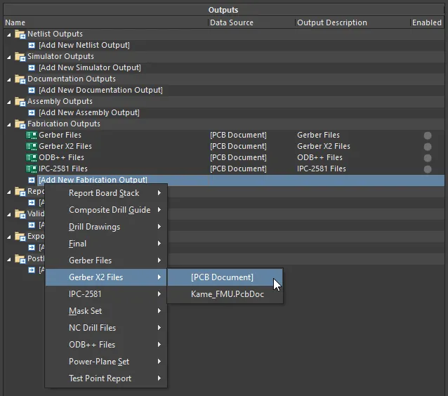
Configure fabrication outputs as part of an Output Job file's Fabrication Outputs. Shown here is an example for Gerber X2 files.
When the OutJob is run – either manually, or as part of the project release process – the fabrication outputs will be generated in accordance with settings defined for the applicable Output Container.

Prepping fabrication outputs as part of a configured OutJob.