
Interactive Routing

Altium Essentials: PCB Routing
This content is part of the official Altium Professional Training Program. For full courses, materials and certification, visit Altium Training.

Routing is the process of defining a connective path between the nodes in each net, by placing PCB design objects, such as tracks, arcs, and vias, on the copper layers to create a continuous connection between the nodes. Rather than placing these objects one by one to build up the connective path, you interactively route the connection.
-
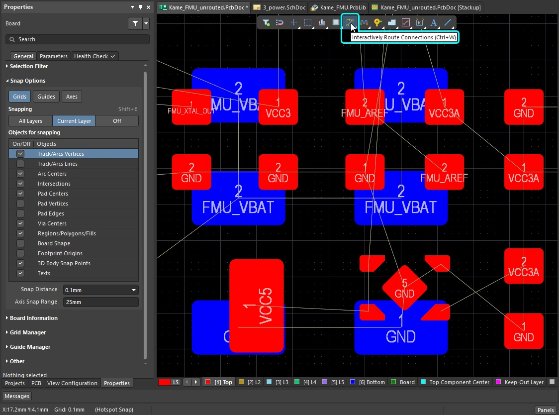
In the PCB editor, interactive routing is an intelligent process. After launching the interactive routing command, you click on a pad to select a connection to be routed. As you move the cursor away from the pad, the interactive router attempts to define a route path from that pad, all the way to the current cursor location. The path that the router defines is controlled by various properties, including the current corner style and the gloss settings.
-
The properties of the tracks/arc being placed are controlled by the Routing Width design rule, and the clearance from other net objects by the electrical Clearance design rule.
-
How the interactive router responds to objects that already exist on the board, such as component pads and routing on other nets, depends on the current Routing Conflict Resolution mode. The mode determines whether the router will Walkaround the obstacle, or Hug the object and Push it if required, or Push it, or Stop, or Ignore it.
Interactively routing a connection - after launching the command and clicking on a connection line, the Interactive Router finds a path from the net object to the current cursor location, weaving around existing objects. A click of the mouse button will place all hatched track segments, Ctrl+Click to auto-complete the route.
Interactive routing can be performed on:
-
A single net – Route » Interactive Routing
-
Two nets configured as a differential pair – Route » Interactive Differential Pair Routing (learn more)
-
A set of selected nets – Route » Interactive Multi-Routing
Building routing proficiency requires a good understanding of how the objects are located in the PCB design space, the following section gives an overview of this. It is also important to understand how to control the display of the routes, to easily see what you are working on within the densely packed design space, there is an overview of this in the second section. The third skill that builds your routing proficiency is to learn how to control the properties of the tracks and vias as you route.
If you have these skills and have come to this page to learn more about the process of routing, then jump down to the working with the interactive router section.
How the Objects are Located in the Design Space
The PCB editor is a grid-based editing environment, the default behavior is for your interactive routing to be placed on the current snap grid. As well as the snap grid, the software includes a number of additional snap features, designed to help you accurately position and align design objects. Together, these features are referred to as the Unified Cursor-Snap System.
There are two core aspects to the cursor-snap system, what the cursor snaps to, and when it will snap.
-
What - the points in space that the cursor snaps to include: user-defined Grids, work Guides, and snap points on the existing Objects.
-
When - the cursor snaps to a snap point: it snaps when it is within the Snap Distance, and snapping is allowed on that Layer.
Demonstration of the cursor-snap features: configure the options in the Properties panel, or by pressing Ctrl+E.
What you snap to |
|
| Snap to grids | Grids are available in both Cartesian and Polar formats ( |
| Snap to objects | Placed objects will pull the cursor into position when it moves within the Snap Distance, based on cursor proximity to that object's snap points (hotspots). Use this to pull the cursor to the center of a track or an off-grid pad, for example. Object snapping can be applied on: all layers, only the current layer, or disabled. Use the Shift+E shortcut to cycle through the modes and monitor the current mode on the Status bar( |
| Snap to guides | Horizontal, vertical, diagonal, and point guides can be placed and used for object alignment, as shown in the video above. Learn more about guides. |
| Snap to object axes | A feature that pulls the cursor, in either the X or Y direction, so that it axially aligns with a hotspot on a placed object that is within the Axis Snap Range (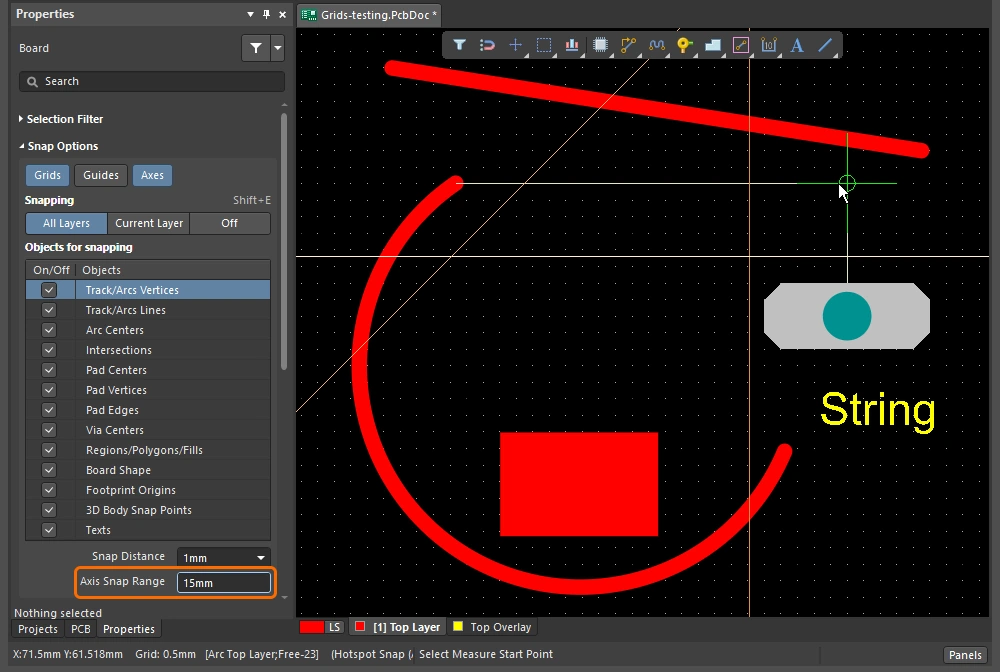 ). ). |
| Controlling the snapping |
|
 ).
). ).
). )
)Snapping to the Grid
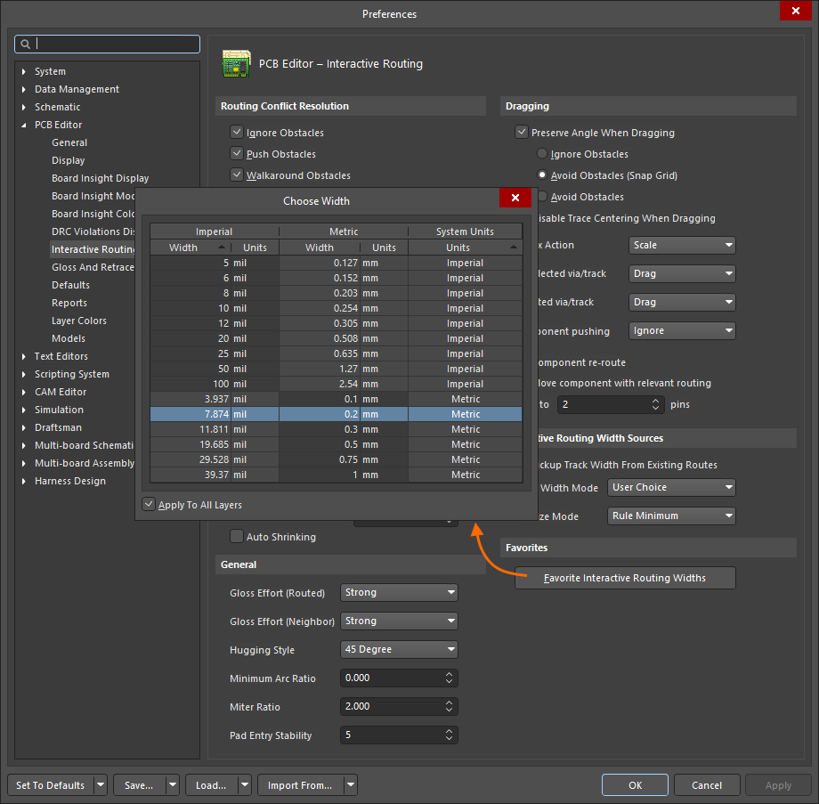
| Toggle the units | Press the Q key to toggle the units between Imperial and metric. The grid units will change, the grid pitch does not. |
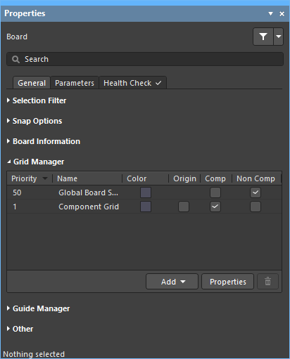
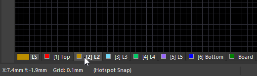
| Active grid? | If there are multiple grids defined under the current cursor location, the highest priority grid (lowest numerical value) is applied as the active grid (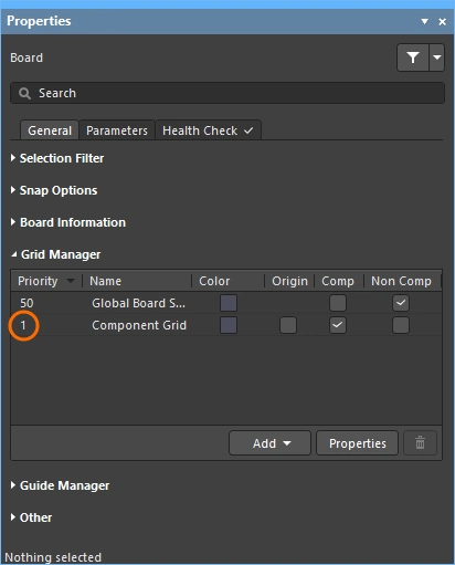 ). ). |
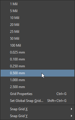
| Quickly select a grid | To select a grid from a pre-defined list, press |
| Edit the grid value | To edit the value of the active grid, press |
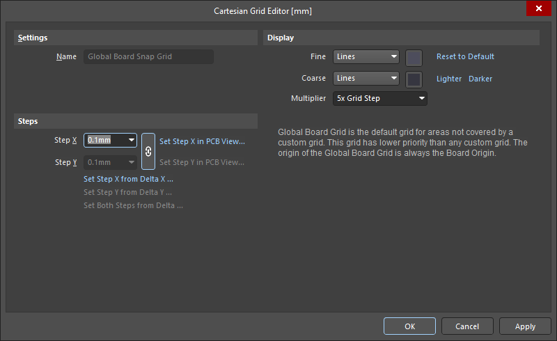
| Managing grids | Individual grids are configured in the Grid Editor ( |
 ).
). ).
). ).
).Learn more about working with grids.
Snapping to Objects
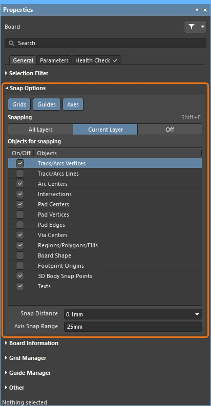
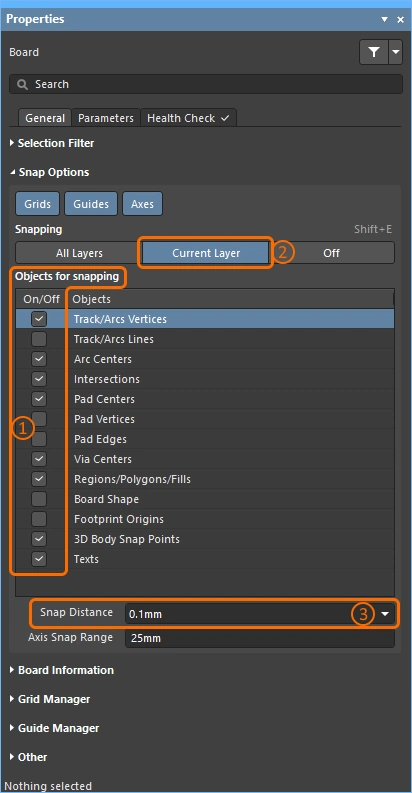
| Snap to objects | The cursor snaps to: enabled Objects for snapping (1), that are on the enabled Snapping layers (2), when the cursor is within the Snap Distance (3)( |
| When to snap | Object snapping has three states, Off, Current Layer, or All Layers. Press |
 ).
).Snapping to Guides and Axes
| To place a guide | To place a guide, use the Place » Work Guides submenu, or the Guide Manager section of the Properties panel ( |
| Guide properties | The visibility, color, and location are managed in the Guide Manager section of the Properties panel (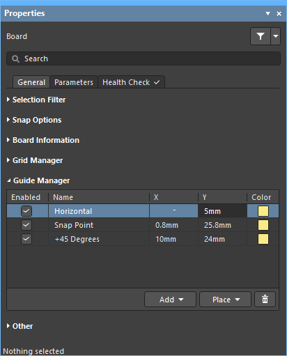 ). ). |
| Snap to Guides | Guide snapping applies: when the Guides Snap Option is enabled (1), and the cursor is within the Snap Distance (2) (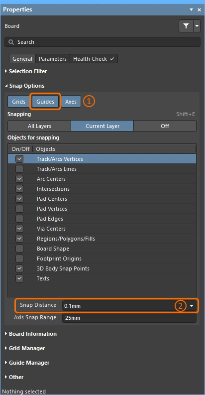 ). ). |
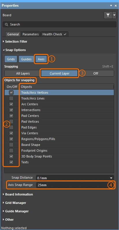
| Enabling axis snapping | Axes snapping applies: when the Axes Snap Option is enabled (1), to enabled Objects for snapping (2), that are on the enabled Snapping layers (3), that are within the Axis Snap Range (4)( |
 ).
).Controlling the Display of the Routes
The printed circuit board design is often very dense and crowded with objects. There are a number of features in the software to help manage object visibility, including: layer visibility, masking and dimming, object visibility and transparency, along with a number of other features.
Use the highlighting, object and layer control features to help interpret the design.
| Single layer mode | Press Shift+S to switch the display to single layer mode. There are 3 modes available, enable your preferred modes in the PCB Editor – Board Insight Display page of the Preferences dialog (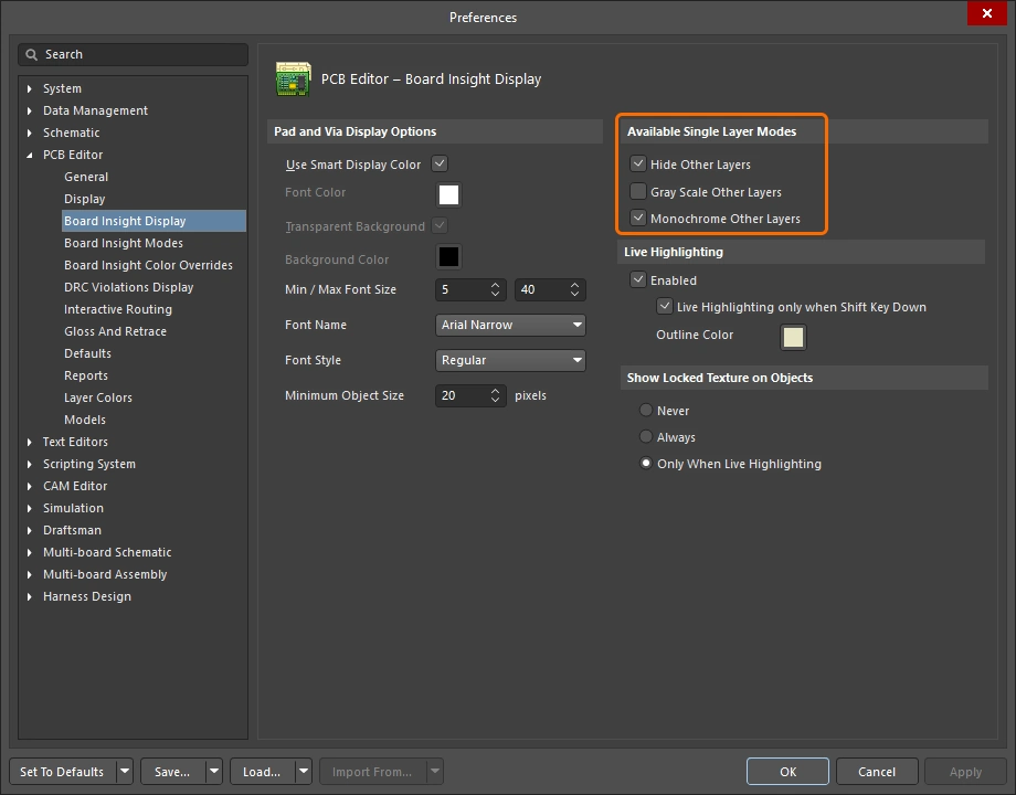 ). Each press of ). Each press of Shift+S steps to the next enabled single layer mode, ultimately returning you to the display of all currently enabled layers. |
| Layer sets | Pre-defined sets of visible layers can be configured and then selected using the Manage Layer Sets button down the bottom left of the editing window (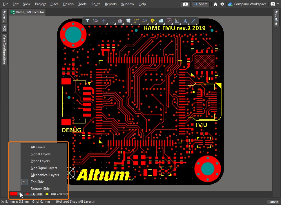 ). New sets are defined in the View Configuration panel, this is demonstrated in the video above. ). New sets are defined in the View Configuration panel, this is demonstrated in the video above. |
| Dim or Mask to fade | To quickly highlight an object of interest, such as a component, a net, a differential pair, or any type of class, browse the object in the PCB panel and enable the Dim or Mask mode (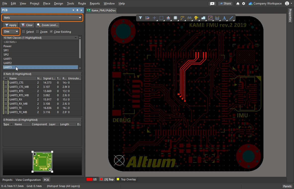 ). Both of these modes fade all objects except those you are interested in, making the objects of interest stand out. The Dim and Mask levels are configured in the View Configuration panel ( ). Both of these modes fade all objects except those you are interested in, making the objects of interest stand out. The Dim and Mask levels are configured in the View Configuration panel (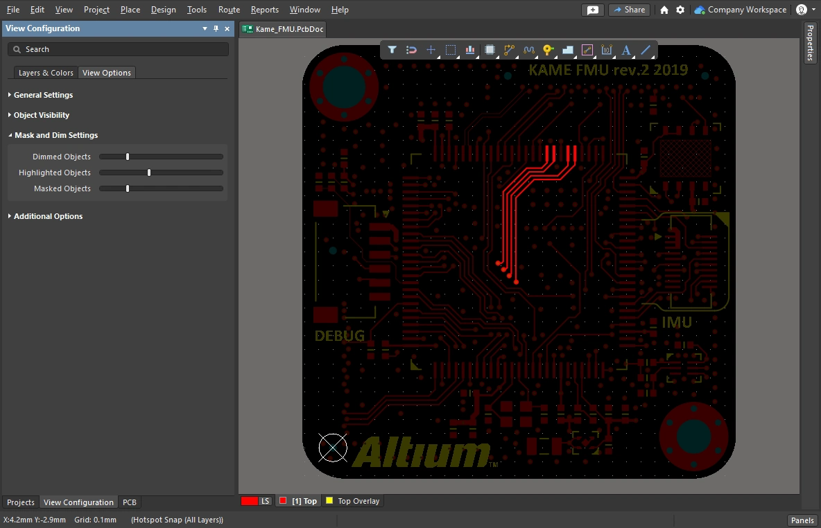 ). ). |
| Clearance boundaries | Enable this to display the required clearance around electrical objects. ( More about controlling the display of the clearance boundaries. |
| Object transparency | The transparency level of each object type can be configured in the Object Visibility section of the View Configuration panel ( |
| The visibility of objects | Hiding objects that are not of interest is a convenient way of de-cluttering the design space (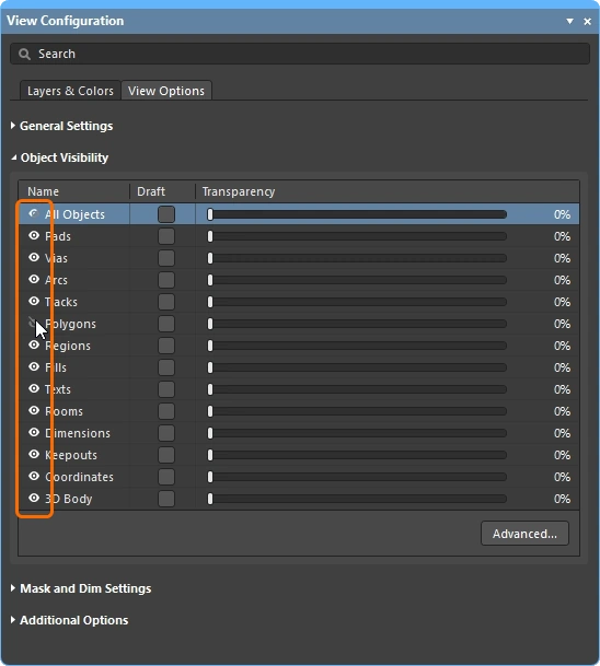 ). Note that the objects are still tested by the constraint system, to hide polygons from visibility and from the constraint system, Shelve them instead. ). Note that the objects are still tested by the constraint system, to hide polygons from visibility and from the constraint system, Shelve them instead. |
| Displaying net names | Configure the options to control the display of net names on pads, vias and tracks In the View Configuration panel (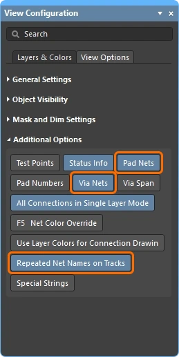 ). Note that net names are always shown at the center of each track segment, but can be repeated if required. The display font properties are configured in the PCB Editor – Board Insight Display page of the Preferences dialog ( ). Note that net names are always shown at the center of each track segment, but can be repeated if required. The display font properties are configured in the PCB Editor – Board Insight Display page of the Preferences dialog (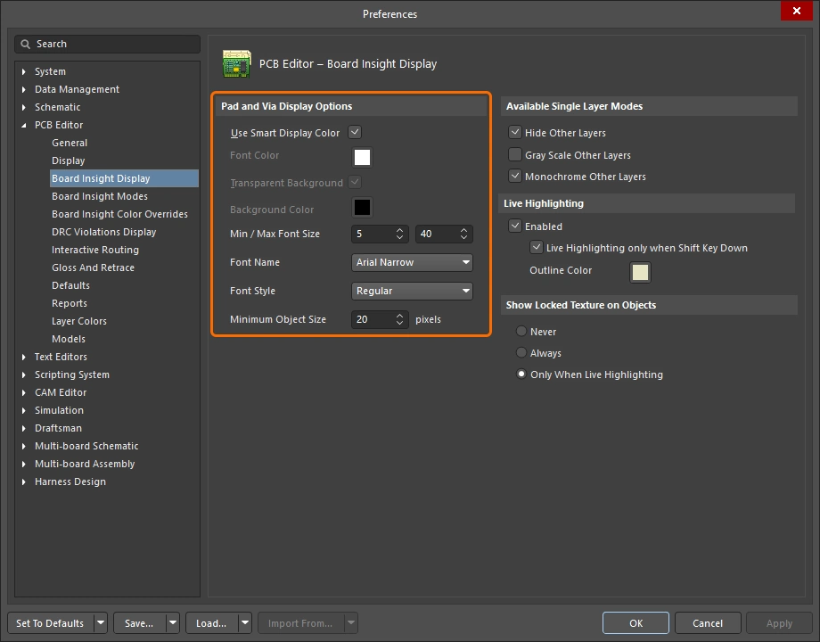 ). ). |
Controlling the Properties of the Route
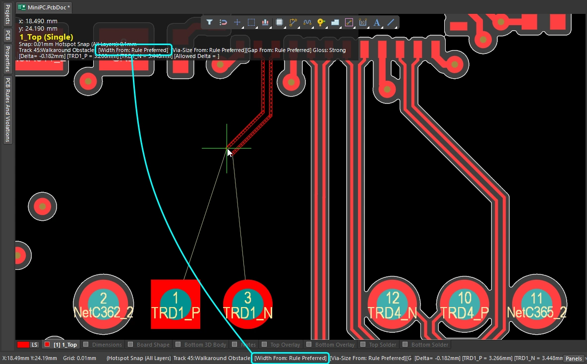
You have configured the clearance, routing width and routing via style design constraints – you are ready to route. When you click to start routing, how does the router know what track width to use, and what via size to use when you switch layers?
Simple demonstration of setting up to route, then selecting the routing width and via style during routing.
 ).
).Changing the Routing Width (0:29)
 ).
). ).
). ).
). ).
).Changing the Routing Layer (1:14)
 ).
). ).
).Changing the Via (1:22)
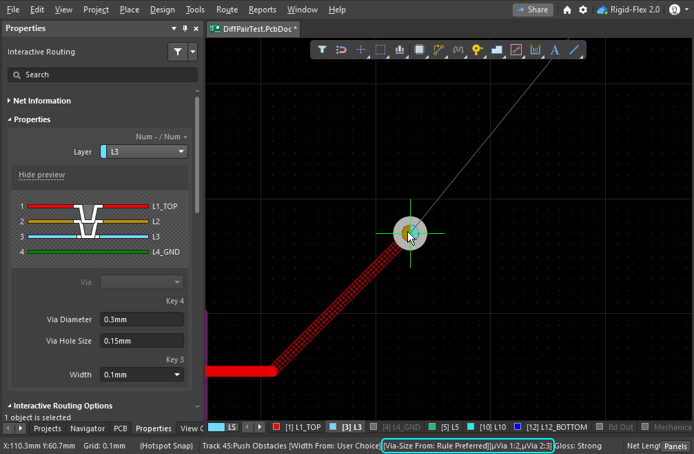
| Routing via | If you switch layers during routing, a via is automatically added, in accordance with the applicable Routing Via Style design constraint. |
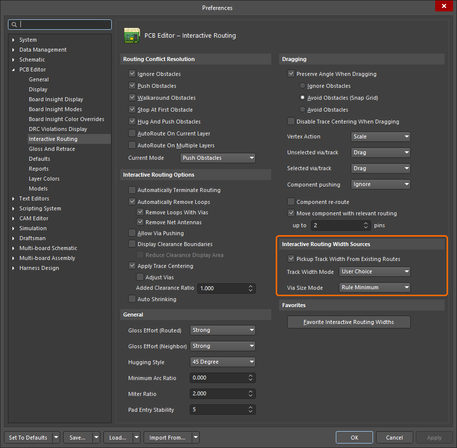
| Default routing via | The size of the via that is used during a layer change is determined by the setting of the Via Size Mode in the Interactive Routing Width Sources options ( |
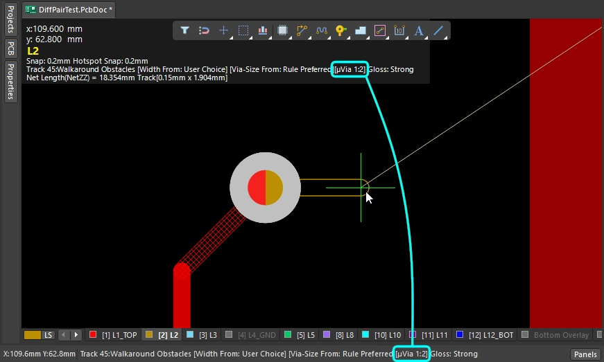
| Cycle available via sizes | Press 4 as you route to cycle through the Minimum, Preferred, or Maximum via size settings (defined in the applicable Routing Via Style design constraint), or choose a User via size (
). The last state is retained as the current Via Size Mode. The current via size mode is displayed on the Status bar and in the heads-up display (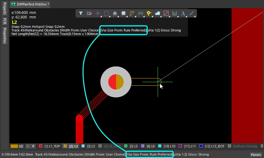 ). ). |
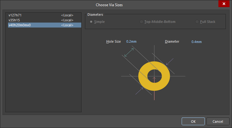
| Choose a different User via size | Alternatively, press |
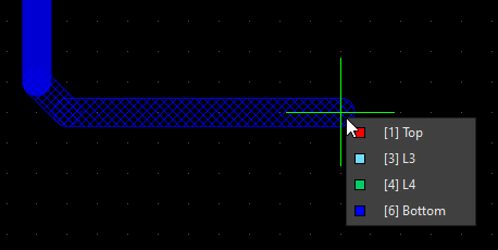
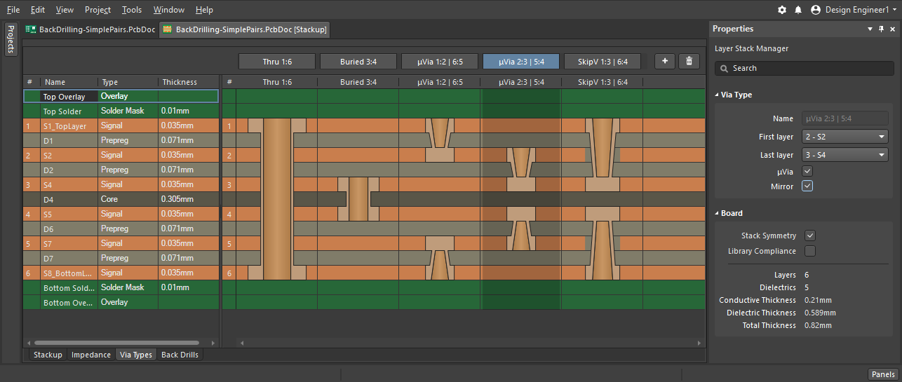
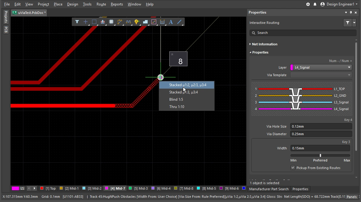
| Cycle the via span | The layers that a via spans is determined by the current Via Type, with the available via types being defined in the Layer Stack Manager ( |
 ).
). ).
). ).
). ).
). ).
).Learn more about vias.
Learn more about defining the via types.
Working with the Interactive Router
You launch the Interactive Routing command and click on a pad or connection line – and what happens? The interactive routing engine attempts to find a path from the copper closest to your click location that is on that net (pad, via, track) up to the current cursor location, placing tracks/arcs of the specified width, laying them out in a neat pattern according to your current router settings.
How does the route leave an SMD pad? How does the routing react when an obstacle is encountered, does it walk around that obstacle, push it, or ignore it? What shape does the corner take, and how does it pass between the pads on other components? Where the previous section outlined how to control the properties of the route itself, this section summarizes the features you have to control the route as it moves through the routing space.
Working with the Interactive Router |
|
| Hatched/solid/hollow track/arc segments | Hatched tracks/arcs are unplaced, solid track/arcs are placed ( When the track attached to the cursor is hollow (not hatched or solid), it is referred to as the look-ahead segment, it will not be placed when you next click. Use this feature to position the end point of the previous segment, without committing to placing the last segment ( |
| How the router forms the corners | During interactive routing, the shape formed by the tracks and arcs that create a corner is referred to as the corner style. Diagonal corners are the most common, but curved corners (created by placing arcs), are also popular. There are 5 available corner styles, 4 of which also have corner direction sub-modes.
|
| How the routing leaves a pad | How the interactive routing engine exits or enters a pad is controlled by:
|
| How the route reacts to an existing object | This is determined by the current setting of the Conflict Resolution Mode. The current conflict resolution mode is displayed on the Status bar ( |
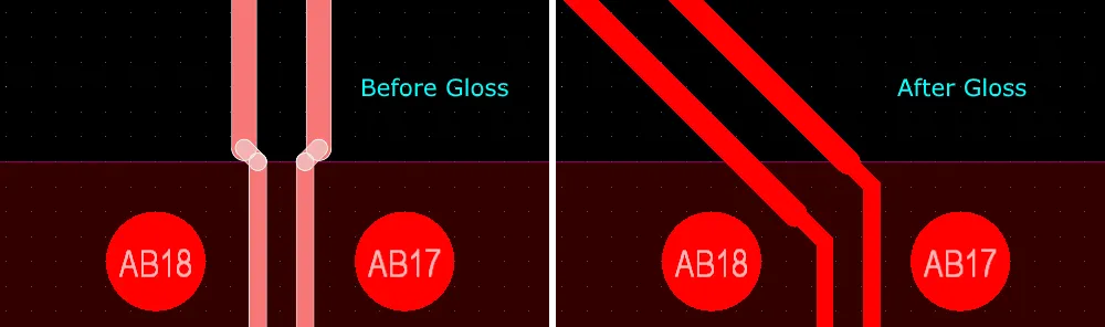
| The smoothness of the new routing | As you move the cursor away from the initial click location the routing re-shapes to find the best path around objects, to reach the current cursor location. The neatness, or quality of that path is determined by the current glossing setting. Glossing is a suite of tools that improve the quality of the routing, attempting to reduce the path length, improve the shape of corners, and reduce their number. It also attempts to avoid right-angles, and prevent acute angles at T-junctions and pads. Glossing also supports differential pairs and will attempt to improve the amount of pair that is balanced in length and separation. Glossing has three settings; Off, Weak and Strong. During interactive routing or interactive sliding use the |
| Auto-complete the connection | As you interactively route a net, hold
If a connection cannot be auto-completed, the tool will return to the last used interactive routing mode. |
| Center the routes between pads / vias | The interactive router obeys the design constraints, automatically routing through a pair of pads at the minimum allowed clearance from the nearest pad. If you prefer the routes to be moved away so that it is spaced between the pads then configure the Apply Trace Centering option. To support the ability to achieve this between any pair of pads, or vias, or pad/via pair, the feature uses a clearance multiplier that it can intelligently adjust the routing clearance up to. |
| Auto-narrow the route | Necking the route to fit through a narrow gap is sometimes the only way to route that net. The Auto Shrinking feature can achieve this, automatically narrowing the route down to just fit through the gap, with the allowed minimum being defined by the routing width constraint. |
| Route selection strategies | Selecting the routes to be worked on is a key aspect of routing. It could be selecting routes to un-route them, to gloss them, to check their properties, or delete them. |
 ).
). ).
). )
)Responding to Obstacles – Conflict Resolution Mode
You launch the interactive routing command and click on a pad. As you move the cursor away from the pad the interactive routing engine lays a path of hatched track segments from the pad you clicked on up to the current cursor location, and as you move the cursor around it updates the hatched segments to best define the route path, in accordance with the design constraints and the current glossing settings.
How the interactive router responds to objects already in the PCB workspace, such as pads or routing on other nets, depends on the current routing conflict resolution mode. The routing conflict resolution mode determines if the interactive routing engine will attempt to push those obstacles, or walk around them, or simply ignore them and route over the top of them.
Simple demonstration of the different behaviors of the conflict resolution modes.
Routing Conflict Resolution Mode |
|
| Current mode | The current routing conflict resolution mode is displayed in the heads-up display ( |
| Changing modes | To change modes during interactive routing (or interactive sliding or via dragging), press the Shift+R shortcut. |
| Available modes | Individual conflict resolution modes can be enabled / disabled in the PCB Editor – Interactive Routing page of the Preferences dialog ( |
Glossing during Routing
Not only do you want the interactive router to find a path and place track segments from the last click up to the current cursor location, you also want that route path to be as short as possible and be created with the minimum number of track segments. To manage this process, the PCB editor includes a Glossing tool.
Glossing is a sophisticated set of algorithms developed specifically to produce cleaner routing and pad entries, that respect the intent of the applicable design rules. Glossing attempts to reduce the path length and also improve the shape of corners and reduce their number, generally resulting in neater routing created from fewer segments. Glossing also leaves sub-net jumpers as they were, and when there are room-based width rules, width changes at the boundary are respected. As you move the cursor around while defining a new interactive route path, all of the yet-to-be committed routing is also automatically glossed.
As well as applying glossing to the net being routed, the interactive routing engine can also gloss the adjacent (neighbor) nets that are being impacted by the net under route.
Simple demonstration of the different results achieved with glossing off and glossing on.
Understanding Glossing |
|
| When does glossing run | The glossing tool runs:
|
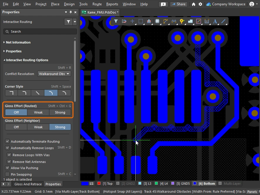
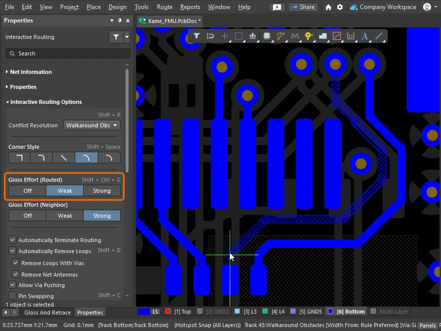
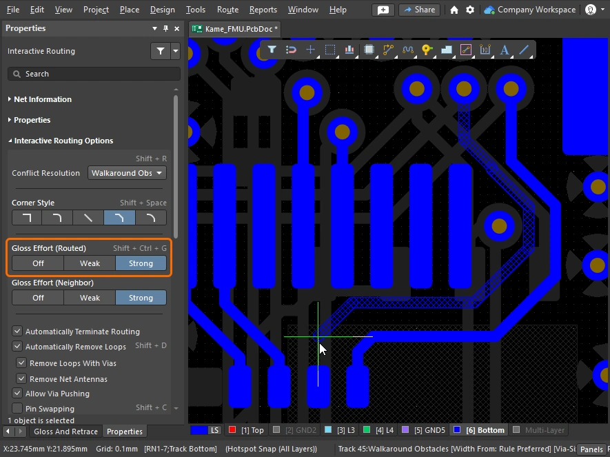
| How strong is glossing | How strongly a route is glossed is controlled by the current Gloss Effort (Routed) setting. Configure the option (
|
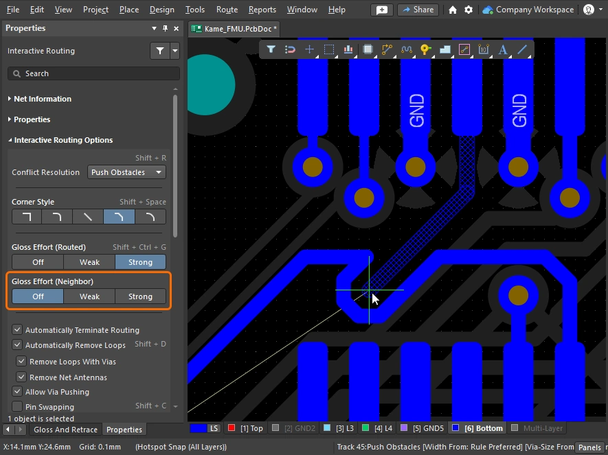
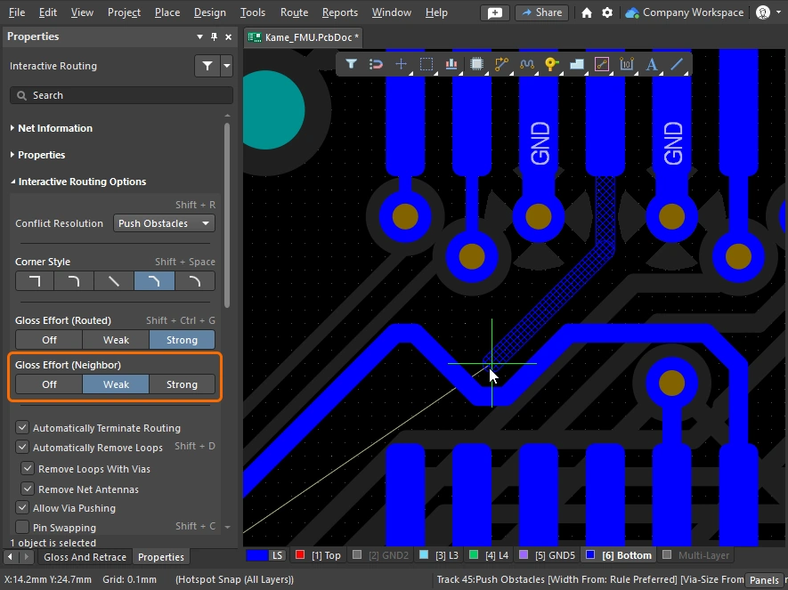
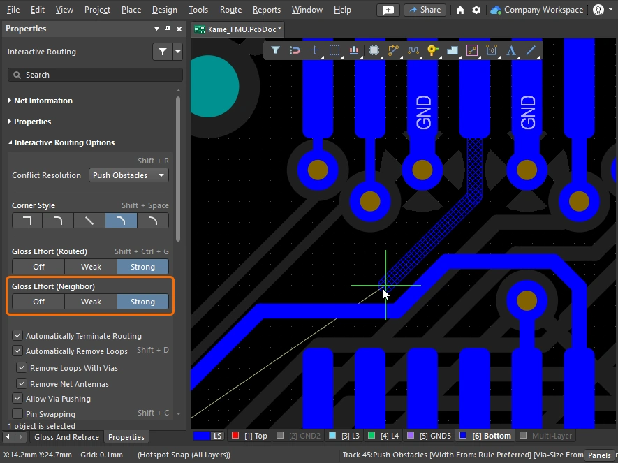
| Glossing the neighbors | During Push or Hug & Push interactive routing or sliding, the adjacent routes, or neighbors, will be impacted. These neighbors can also be glossed, based on the Gloss Effort (neighbor) setting (  ). Gloss effort (neighbor) settings ). Gloss effort (neighbor) settings |
| Hugging - how glossing wraps around other objects and forms corners | How the glossing engine wraps the route around other objects and forms the corners is referred to as hugging. The available Hugging Style settings include:
|
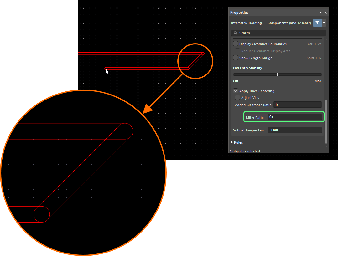
| Controlling the properties of the corner | If corners are being formed with straight track segments, the default behavior is for the glossing engine to apply a small miter to a 90 degree corner, with the size controlled by the Miter Ratio setting. Miter ratio settings If corners are being formed with arcs, the minimum arc size is controlled by the Minimum Arc Ratio. The Minimum Arc Ratio is applied during any angle interactive routing and also during interactive sliding with Mixed Hugging Style. The ratio is used to determine the minimum radius arc allowed, when the arc radius falls below this minimum the arc is replaced by track segments. Minimum arc ratio settings |
| Inhibit glossing during routing and sliding | There may be times when you want to temporarily turn off glossing. Glossing can be inhibited during routing by pressing and holding the Ctrl+Shift shortcut keys - as soon as the keys are released glossing resumes at the current Routing Gloss Effort setting. Note that the status bar will not reflect this state; it will continue to display the last selected state. |

 ).
).

More about the interactive routing options.
The slides below show simple examples of the different Gloss Effort (Routed) and Gloss Effort (Neighbor) settings.
Miter or Curve the Corners
Corners can be defined using short, straight track segments (miters), or they can be created using one or more arcs. The images below show the two most popular corner styles; Track 45 and Any Angle.


Mitered Corners
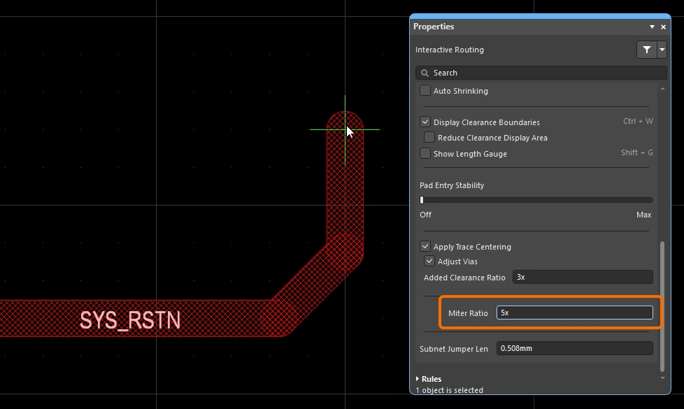
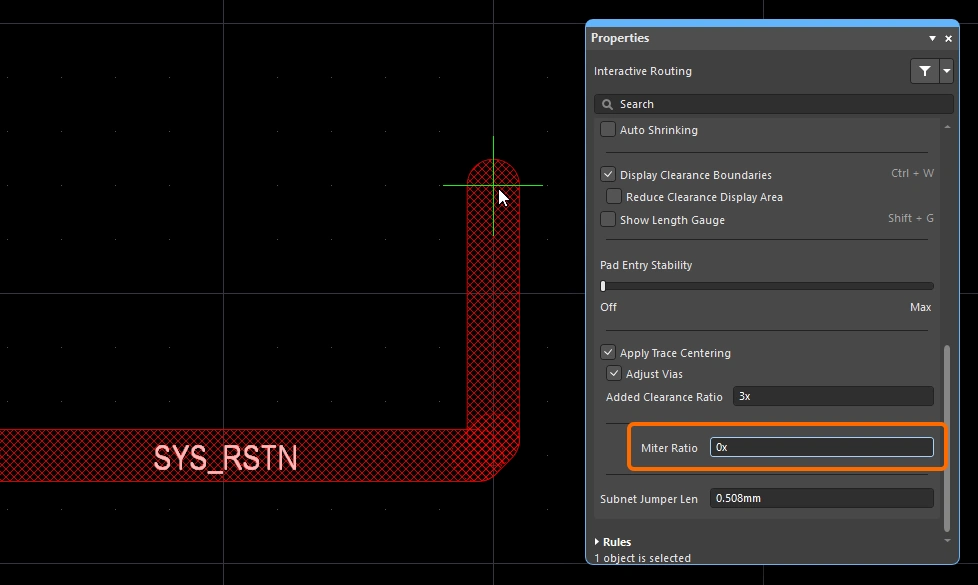
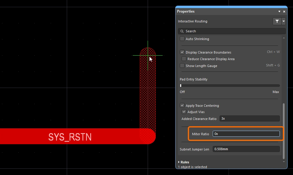
The most common routing corner shape is 45 degree mitered (diagonal) corners. Switch to the Track 45 corner mode to route diagonal corners. Complimenting this, the interactive routing engine also includes a miter ratio feature that ensures that tight corners retain a miter, making it impossible to inadvertently create right angle or acute corners during routing.
The Miter Ratio is defined as:
Miter Ratio x current track width = separation between the walls of the tightest U-shape that can be routed for that miter ratio
 The miter ratio controls the minimum sized miter that is automatically added to the corner.
Both interactive routing and interactive sliding include a Miter Ratio option. Enter a positive value equal to or greater than zero. Examples of the same trace routed with different values of the Miter Ratio option are shown below.

 )
) )
) ).
). )
) ).
).Curved Corners
Many designers require curved corners. Curved corners can be placed as you route – with either the Line 45/90 With Arc corner mode or the Line 90/90 With Arc corner mode. The Line 90/90 With Arc corner mode will force a 90-degree corner though, so use the Line 45/90 With Arc corner mode if the route needs to continue at 45 degrees. The arc can be interactively resized during routing using the ![]() and
and ![]() keys (hold
keys (hold Shift to accelerate the resizing process).
When a curved corner style is selected during interactive routing, the glossing engine will favor a tangential path around existing curved objects. That is, the arc placed to create the corner is located and radially sized to exactly curve around the existing object. This is designed to form smooth routing through a sea of curved shapes, for example, the escape via pattern under a BGA. If the Routing Gloss Effort is set to Strong it can result in the straight track segments between the arcs being placed at an angle other than horizontal or vertical.
If you require all of the straight track segments to placed exactly horizontal or vertical, with curved corners, it can be more efficient to route with diagonal corners and then gloss the routing to curve the corners. This is achieved by setting the Hugging Style set to Rounded, the Gloss Effort to Weak, and then running the Gloss Selected command, with the routing selected.
To curve the corners of existing routing, set the Hugging Style to Rounded, Gloss Effort to Weak, and then select the routing and run the Route » Gloss Selected command.
Snake Routing
As well as using the arc corner modes as just discussed, a style of smooth flowing, point-to-point routing can also be achieved by setting the corner style to Any Angle and the Routing Gloss Effort to Strong. This creates what is referred to as Snake Routing. Use this when the routing requires any angle routes to flow through multiple curved objects, as shown in the example video below.
Snake routing – the corner style is set to Any Angle.
Using the Net Length Gauge
If there is a Length constraint and/or a Matched Length constraint defined, you can monitor the length during interactive routing (and interactive length tuning), by displaying the Length Tuning Gauge. While you are routing, use the Shift+G shortcut to toggle the Gauge on and off.
The Gauge shows the Current Routed Length as a number, and the red/green slider shows the Estimated Length. During interactive routing, it might seem confusing that the Routed Length has not even reached the constraint minimum value, but the Gauge slider is somewhere between the constraint minimum and maximum - as it is in the image below. That is because during interactive routing the slider represents the Estimated Length, where:
Estimated Length = Routed Length + distance to target (length of connection line)
 The Gauge displayed as a Length design constraint is being obeyed during Interactive Routing - it shows the current Routed length as a number, the slider shows the current Estimated Length.
The Gauge functions as follows:
-
A rectangular box that defines the outline of the Gauge.
-
Two vertical yellow bars that indicate the minimum and maximum lengths allowed. The minimum and maximum are determined from the tightest set of constraints defined by the design constraints, as described above.
-
The green vertical bar that represents the target length, which will either be a manually entered value, a length used from an existing selected net, or the mid-point of the valid length range when calculated from design constraints.
-
A red or green slider that shows the current Routed Length of the net (during length tuning), or the Estimated Length (during interactive routing). The slider changes from red to green when the current length moves from being out-of-range to being within the minimum and maximum lengths allowed.
-
The current Routed Length (length of the placed tracks and arcs) is displayed as a numerical value overlaid on the Gauge slider (62.781mm in the example image).
-
The gauge's rectangular outline indicates the total range of possible lengths, the meaning of its upper and lower limits depends on the target length mode you have chosen.
-
If the mode is Manual or From Net and there is no applicable Length constraint, the lower limit of the slider box will be the length of the current net, and the upper limit will be the specified Max Length.
-
If the mode is Manual or From Net and there is an applicable Length constraint, the lower limit of the slider box is taken from the constraint or the current route length (whichever is smaller), the upper limit is defined by the user.
-
If the mode is From Rule and there is an applicable Length constraint, an applicable Matched Length constraint, or a combination of both, the lower limit of the slider box is determined from the constraint or the current route length (whichever is smaller), the upper limit of the slider box is determined from the constraint's MaxLimit.
-
Routing Pad Entries
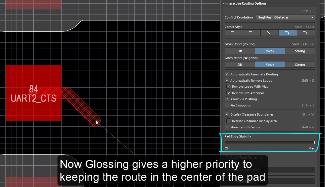
The interactive routing engine leaves and enters surface mount pads according to the applicable SMD pad entry design constraints. As you route or (slide the route), the exit / entry is constantly being glossed, according to the current gloss strength setting. Glossing is a sophisticated set of algorithms developed specifically to produce cleaner routing and pad entries, that respect the intent of the applicable design rules. The glossing engine also includes the Pad Entry Stability feature, which enables the designer to instruct the glossing engine to favor the pad centerline.
SMD Pad Entry Design Constraints
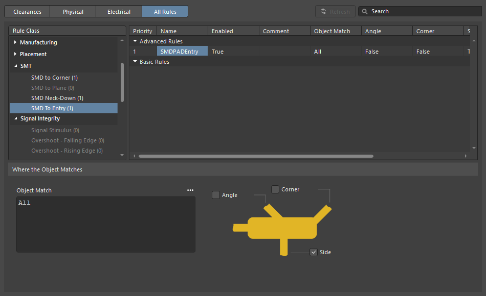
The SMT Design Constraints control how the interactive router exits and enters surface mount pads, these should be configured before starting the routing process. Open the PCB Rules and Constraints Editor dialog (click Design » Rules from the main menus) to create and configure these design rules.
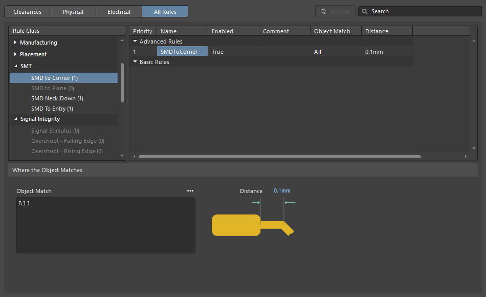
| SMD to Corner | This constraint defines the distance from the edge of the pad to the center of the vertex where the first corner is located. The value should be greater than the width of the track or the applicable clearance rule (whichever is greater). If it must be less than that, there are three ways you can approach this:
|
| SMD Entry | The constraint defines where the route is allowed to enter the pad. For this constraint, the Side of the pad is the longer edge. |
Pad Entry Stability
The Pad Entry Stability slider protects centered pad entries. It applies during glossing to protect an already-centered pad entry (exit), it does not attempt to re-center an existing off-center pad entry.
-
0 (Off) =no protection -
10 (Max) =maximum protection
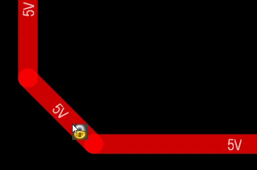
Use the Pad Entry Stability feature to help keep the route in the center of the pad.
Center Routes Between Pads
The interactive routing engine obeys the design constraints – as you route between component pads and vias it places track segments at the minimum clearance specified by the applicable clearance constraint. A common desire of board designers is to center the routes between pads and vias wherever possible, maximizing the separation between the net on the pad or via, and the net being routed.
The Apply Trace Centering option does this. To allow the centering algorithm to be flexible and to be applied between any two pads, any two vias, or any pad and any via, the desired centering distance is specified as a multiple of the applicable clearance constraint, where:
Distance = Clearance + Added Clearance Ratio x Clearance
The interactive routing engine will attempt to route around the target pad/via at this Distance, automatically reducing (and centering) it when the distance from the other edge of the trace to the nearest pad or via becomes less than Distance.
Where possible, adds an additional clearance between the net being routed or dragged and existing pads/vias.
Pad Entry Stability |
|
| Apply trace centering | When the Apply Trace Centering option is enabled, trace centering is applied during interactive routing and interactive sliding. When the routing engine detects that a route is passing between pads / vias it attempts to center the route, up to a maximum distance of the applicable clearance constraint plus the applicable clearance constraint multiplied by the Added Clearance Ratio. Use the Disable Trace Centering When Dragging option to disable centering during interactive sliding. |
| Center between what? | The trace centering feature does not require the pads to belong to the same component, it is able to center between any two pads, any two vias, or any pad and any via. Use the Adjust Vias option to enable/disable centering between via-via or via-pad combinations. |
| Where is the center? | Rather than attempting to identify the center between the relevant pads/vias, the feature uses a multiplier of the applicable clearance, which is then added to the clearance. For example, if the applicable clearance is 0.15 mm, setting the option to 2 would instruct the routing engine to clear existing pads and vias by 0.15 + 2*0.15 = 0.45 mm where possible. The routing engine can then reduce this clearance down to the specified clearance if required. |
Auto-Shrinking during Routing
A challenge with modern component technology is needing to route a net at different widths as it travels across the board. At a local-level it could be the need to neck-down the routing as it passes between component pins. At the board-level it could be the need to narrow all of the routes that pass between the balls under a BGA component. Interactive routing supports these requirements in different ways.
Localized Auto-Shrinking
A common challenge during interactive routing is when a route approaches component pads but does not quite fit between them. The designer can interactively narrow the route (within the sizes allowed by the design constraints), route a narrower trace between the pins, then interactively widen the width and continue routing that net. Instead of controlling this process manually, you can enable the Auto Shrinking feature.
Area-based Auto-Shrinking
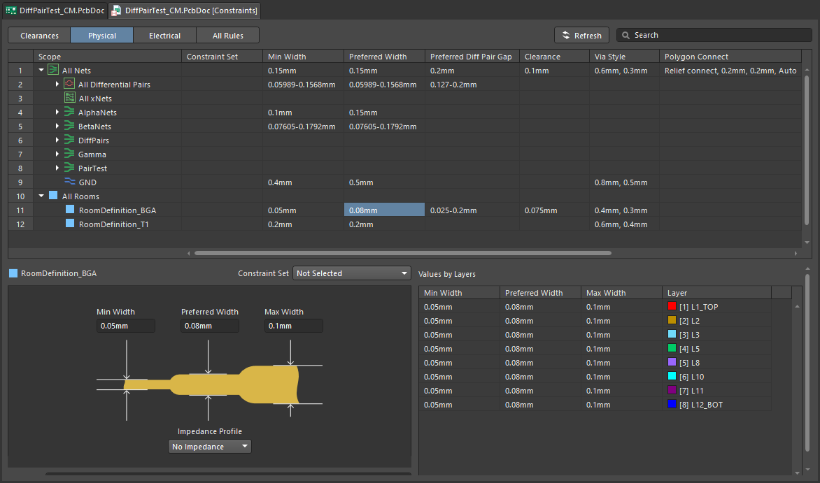
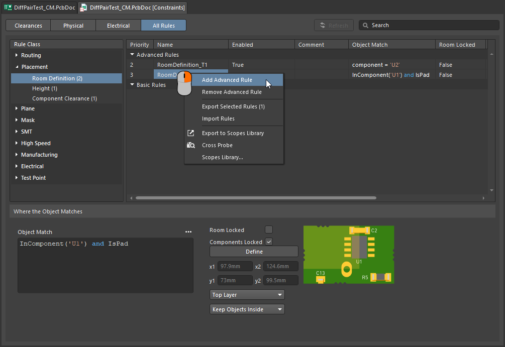
BGA components use an array of small, closely located pads. This makes them challenging to route, often requiring the routing width to be reduced to route to the inner rows of pads. This can be achieved manually during interactive routing using the techniques described on this page. You can also automate this width-switching behavior by adding a placement room and a room-based routing width constraint. Because the interactive router obeys these constraints, tracks will automatically neck and expand as the room is entered or exited.
The routing width and clearances are automatically adjusted within the room.
Shrink the Routing within an Area |
|
| Define the area | The area where the routes need to be reduced in width is identified by defining a placement room constraint ( |
| Define the width | The routing width is defined by the applicable Routing Width Constraint ( |
 ).
).Learn more about defining constraints within a room.
Follow mode – Tracing an Existing Shape
A challenging requirement is to place a route so that it follows an existing shape or contour. The contour could be an obstacle, a cutout or the board edge, or an existing route.
Rather than having to route against the contour using careful and accurate mouse movements and click actions to ensure the new route hugs the contour, in Follow mode, you click to nominate the contour that you want to follow, then move the cursor to define the route direction. The interactive router will add track and arc segments so that the new route follows the contour in compliance with applicable design rules. This feature is particularly useful when placing curved routes.
Use Follow mode to exactly route along an existing shape.
Route to Follow a Contour |
|
| First step | Launch the Interactive Routing command and click on the net to be routed, in the usual way. |
| Enable Follow mode | With the route started, press In the video above the board cutout is followed for the first route, then the previous route is followed for each of the other routes. |
| To place the follow route | The next left-click of the mouse is interpreted as the termination point for the follow route, after clicking you revert back to regular interactive routing. |
| To abort Follow mode | Press Backspace to drop out of Follow mode and revert to regular interactive routing. Alternatively, press Esc to abort Follow mode and also abort routing this connection. |
| Differential pairs | Follow mode also supports differential pairs (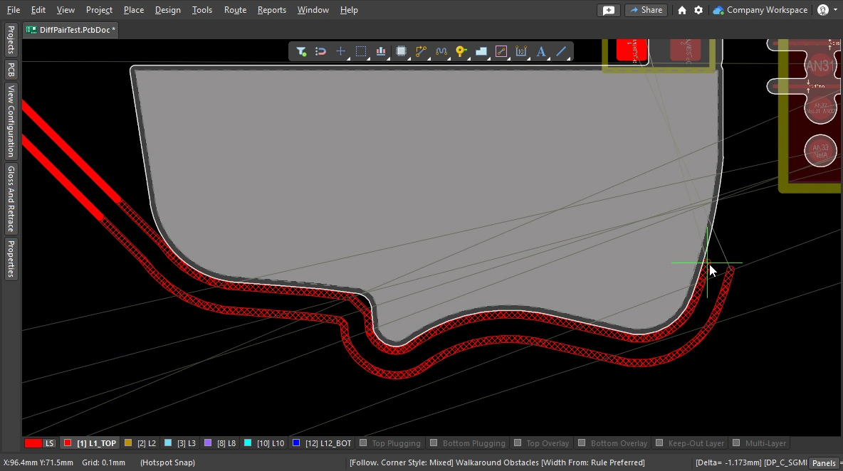 ). ). |
Intentionally shorting different nets
It is not uncommon to need to intentionally connect two different nets. An example could be when you need to connect an Analog ground and a Digital ground in a controlled way. This is achieved by connecting the two nets through a Net Tie component. A Net Tie component is nothing more than a controlled short circuit, allowing you to decide the location on the board where the nets connect.
The challenge with routing towards a Net Tie pad is the rules engine will see that a violation is about to occur and prevent you from routing to the Net Tie pad. This will not occur if you start routing from the Net Tie pad. Alternatively, you can temporarily switch the Routing Mode to Ignore Obstacle.
To route a Net Tie, route out from from the Net Tie pads.
Learn more about Intentionally Connecting Two Nets.
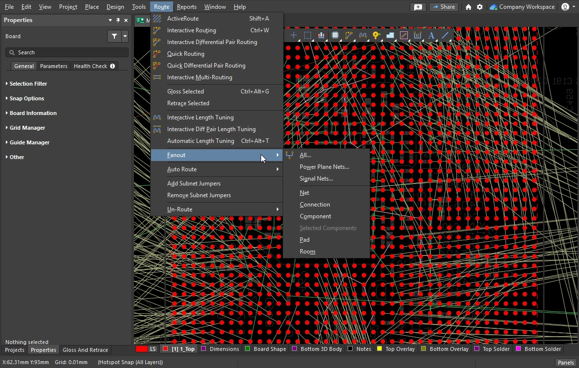
Fanout and Escape Routes
Altium Designer includes surface mount component fanout tools, which also support BGA escape routing. The escape routing engine attempts to route each pad out to just beyond the edge of the device - making routing connections to them much easier. Fanout is designed to be run prior to interactive or auto-routing, and will only attempt to fanout unrouted components.
Fanout and escape routing is launched from the Route » Fanout sub-menu of the main menus or using the Component Actions » Fanout Component command from the component's right-click menu.
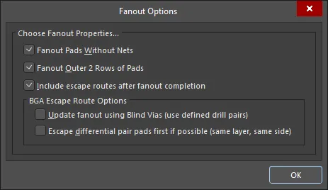
Setting Fanout Options
After selecting any of the fanout commands, the Fanout Options dialog opens. The dialog includes controls that let you specify fanout and escape routing options, as well as options for using blind vias. The blind via option is only available if there suitable blind Via Types defined in the Via Types tab of the Layer Stack Manager.
 A fanned out BGA, the pads are shown solid and the fanout tracks and vias semi-transparent. The fanout is based on the settings in the dialog, in accordance with the Fanout Control constraint.
Fanout Options ( |
|
| Fanout Pads Without Nets | Enable this option to fanout pads from the component even if they have no nets assigned to them. When this option is disabled, only pads with nets assigned will be fanned out. |
| Fanout Outer 2 Rows of Pads | Enable this option to also fanout pads from the outer two rows (which are usually easily routed). |
| Include escape routes after fanout completion | Enable this option to add escape routing to each fanout. Escape routing places tracks onto the fanout vias and component pads, bringing them out to the edges of the component. |
| Update fanout using Blind Vias (BGA escape routing only) | Enable this option to drop blind vias between configured drill-pair layers in the layer stack. When this option is disabled, only through-hole vias will be dropped regardless of drill-pair layer settings. If there are no drill layer pairs defined to be able to use blind vias, this option will appear as Cannot Fanout using Blind Vias (no layer pairs defined). |
| Escape differential pair pads first if possible (same layer, same side) | Enable this option to fanout and escape route any assigned differential pair nets together, before performing other fan out operations, effectively keeping their routes together. The fanout will place escape routing tracks on to the same layer and as adjacent as possible. |
 )
)Fanout Behavior
Used inner pads are fanned out first using the traditional dog-bone (a short route with a via on the end) to access another layer, and then from the via they are escape-routed out just beyond the edge of the device, working through the available routing layers until all pads have been escape routed. A report of all pads that could not be escape routed is generated and opened, click on an entry in the report to cross probe to the PCB and examine that object.
 Example of fanout and escape routes for a 1mm pitch BGA.
Performing a Fanout |
|
| Running a fanout | Select the required fanout command from the Route » Fanout submenu. Regardless of which menu command is chosen, the Fanout Options dialog will open. When it has been configured and you click OK, the chosen fanout will be performed. |
| What controls the fanout process? | As well as the settings in the Fanout Options dialog, fanout and escape routing is done in accordance with the applicable design constraints, including the Fanout Control, Routing Width, Routing Via Style (for fanout vias), Routing Layers, and the Electrical Clearance constraints. |
| Why does nothing happen when I run a fanout command? | This could be due to:
|
| Why do some of the fanouts show violations as soon as they have been placed? |
|
Fanout Commands
All of the fanout commands are available in the Route » Fanout submenu. You can also fanout the component currently under the cursor, right-click on a component and select Fanout Component from the context menu.
 )
)Interactive Multi-Routing
There are often groups of signals that need to be routed together along the same path on the PCB, such as the Address and Data busses. To help with this, the interactive router includes an interactive multi-routing command. The multi-route process is configured in the multi-routing Properties panel (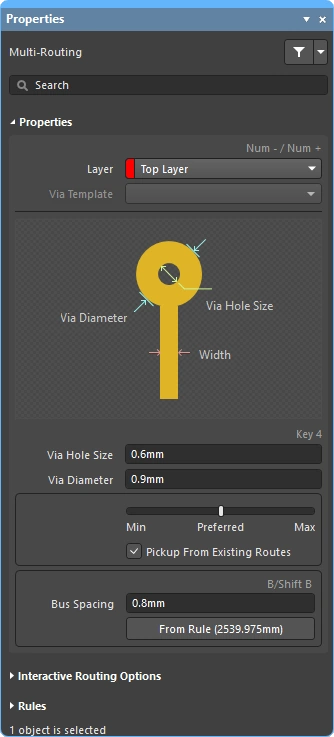 ), and can also be controlled using shortcuts.
Multiple selected nets can be simultaneously multi-routed.
During interactive multi-routing, press Tab to open the Properties panel and configure the settings.
Performing a Multi-route
| Choose the connections to route | Before launching the command, select the source pad of each net to be included in the route. Shift+click to select individual pads, Ctrl+click and drag to draw a selection rectangle and sub-select multiple child pads in a component. |
| Start multi-routing | The Interactive Multi-Routing command is accessed from the Route menu or the Active Bar (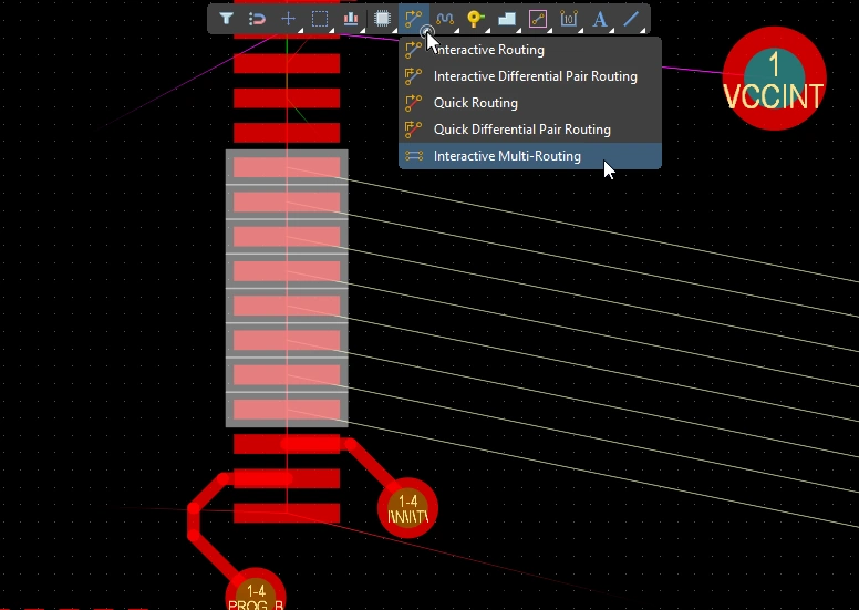 ). After launching the command, you will be prompted to click to begin multi-routing. Simply click within the design space at the point where you require to lay down the first set of track segments, then continue routing as required toward your target destination. ). After launching the command, you will be prompted to click to begin multi-routing. Simply click within the design space at the point where you require to lay down the first set of track segments, then continue routing as required toward your target destination. |
| Controlling the track spacing | Use the B shortcut to decrease the bus spacing and the (Shift+B) shortcut to increase it, in increments of the current snap grid. Press C to converge the bus spacing to the minimum allowed by the applicable Routing Width design constraint. |
| Changing the route properties | Use the same shortcuts as for the Interactive Routing to perform other actions, such as cycle through the conflict resolution modes, switch routing layers, change via options, and so on. |
Multi-routing Properties ()
| Layer | The layer that the multi-route is being placed on. Use the drop-down to select a different layer, vias will be added automatically. Alternatively, use the layer-change shortcuts. |
| Via Template | If the via is associated with a template the template name is displayed here and can be changed using the dropdown. Learn more about pad and via templates. |
| Via Hole Size | Displays the via hole size that will be used. The value can be edited directly, within the range allowed by the applicable routing via style design constraint. More about selecting the via size and via type during routing. |
| Via Diameter | Displays the via diameter that will be used. The value can be edited directly, within the range allowed by the applicable routing via style design constraint. More about selecting the via size and via type during routing. |
| Routing width selector | Use the slider to set the routing width to the Min/Preferred/Max value defined in the applicable routing width constraint. |
| Pickup From Existing Routes | When this option is enabled and you are routing from an existing track, the existing track width is used (overriding the width chosen in the sliding selector). |
| Bus Spacing | Enter the desired bus spacing or use the |
| From Rule | Click the button (or use the C shortcut) to change the bus spacing to be the distance defined by the applicable Electrical Clearance constraint. |
Interactive Routing Options
More about the interactive routing options.
Multi-routing Design Constraints (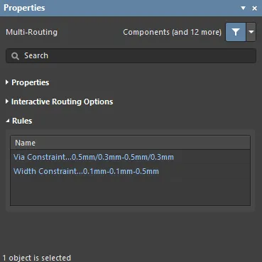 )
)
Applicable routing and via constraints will be listed under the Rules section of the Properties panel.
Subnet Jumpers
One of the great strengths of an FPGA-based design is that the routing challenge can be resolved in both the PCB and the FPGA, potentially resulting in fewer routing layers and a simpler PCB. For this to be a reality, the design system must support both PCB-driven and FPGA-driven pin swaps. Altium Designer supports pin swapping in the PCB editor, from simple 2-pin components through to high pin-count FPGAs.
To support pin swapping at any stage of the design process, including on the routed PCB, the PCB editor can add and remove small routing connectors, called subnet jumpers. A subnet jumper is a short segment of track that the software recognizes as an element that can be easily placed and removed; either manually via the Add and Remove Subnet Jumper commands in the Route menu, or automatically by the routing engine if you route to a swappable pin during interactive routing.


 ).
).A subnet jumper is automatically added during interactive routing if the target is the swappable route, rather than the same-net route.
 ).
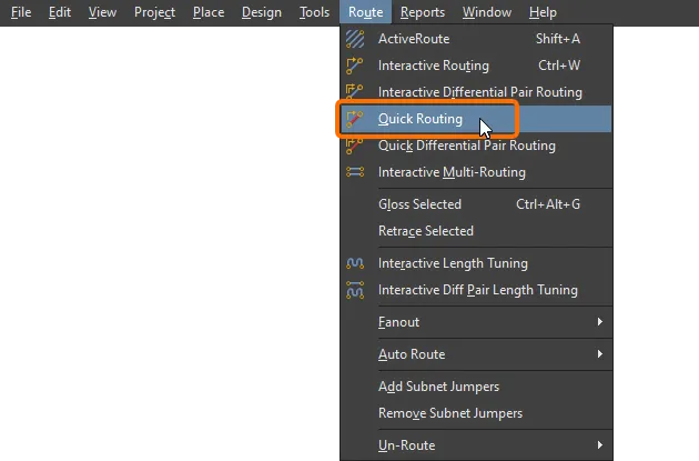
).Quick Routing Tools
For designers whose designs are less demanding there is also a pair of quick routing commands. The Quick Routing tool helps maximize routing efficiency and flexibility in an intuitive way, including following cursor path for laying route sections, single-click routing completion, pushing or walking around obstacles, and automatically following existing connections, all in accordance with applicable design rules.
The Quick Routing command (accessed from the main menu and the Active Bar) offers lighter routing with less settings and capabilities, suitable for simpler designs. Its general behavior and shortcuts are the same as the standard Interactive Routing command.
Summary of Capabilities |
|
| Includes | Capabilities include:
|
| Does not support | This router is referred to as Quick because it offers a reduced feature-set. Features that are not included in the Quick Router include:
If you need any of these features, use the Interactive Routing tool. |
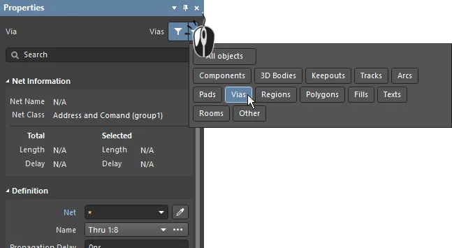
Net Information (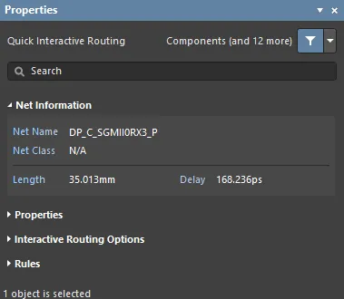 )
)
During interactive routing and interactive sliding, the net under edit is detailed in the Net Information section of the Properties panel.
More about the net information.
Quick Routing Properties (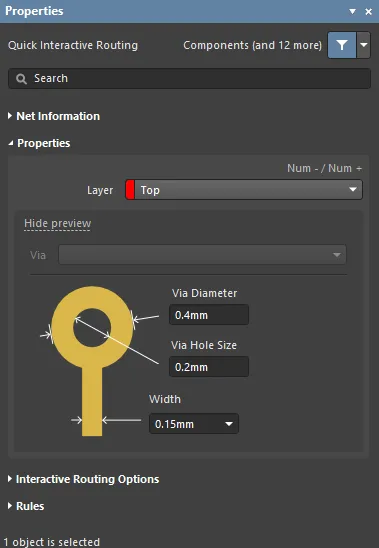 )
)
During quick interactive/differential pair routing, the properties of the route objects can be edited in the Routing Properties section of the Properties panel.
More about the routing properties.
Interactive Routing Options (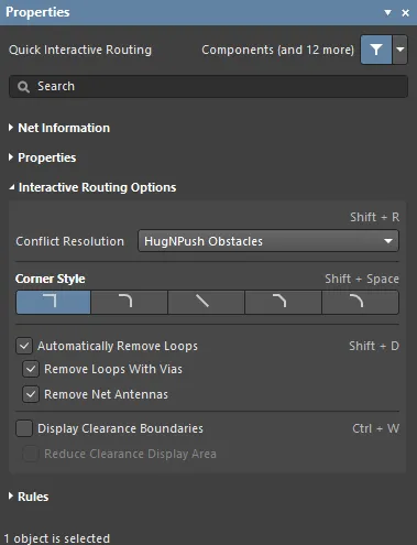 )
)
Available interactive routing options are listed under the Interactive Routing Options section of the Properties panel.
More about the interactive routing options.
Design Constraints (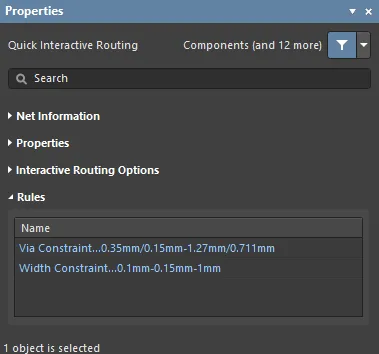 )
)
Applicable routing and via constraints are listed under the Rules section of the Properties panel.
Updating the Routing
Routing is an interactive process, requiring the designer to constantly adjust, update, or even remove the existing routing, as they complete the board design.
The simplest way to change the routing is to click, hold, and drag that route to a new location. Sometimes sliding is not the solution, you need to reroute a section instead. The interactive routing engine supports this, using a feature called Loop Removal. This feature monitors the interactive routing process, and if it detects that a new path has been routed in parallel to an existing path, it automatically removes the old redundant segments.
Dragging existing routes is called Interactive Sliding, with the controls for this displaying in the Properties panel during sliding ( ). During sliding, the interactive routing engine will attempt to maintain the quality of the routing, while complying with the applicable design constraints. Key features that control the sliding process include: the routing conflict resolution mode (response to obstacles), the gloss strength (effort in tidying the results), and hugging (wrapping around obstacles and forming corners). There are a number of features that support interactive sliding, including T-junction and vertex dragging, via dragging, as well as differential pair dragging support.
There are also features to support dragging routed components.
Strategies for Selecting the Routing
One of the great challenges with interactive software tools is interfacing those tools to the designer's fingertips so they can easily and fluidly move between the various tasks, such as creating, reshaping and cleaning the routing. For this to happen, it must be easy to select the routes of interest.
Perhaps the easiest way to select a route is to click once on any object in the net of interest, and then press the Tab key, as shown in the video below.
Demonstration of route selection techniques using the Tab shortcut.
When you press Tab:
-
The first time – select all connected routing objects on the same layer
-
The second time – select all connected routing objects on all layers
-
The third time – select all objects on that net in the design space (skipped if there are no unconnected net objects)
-
The fourth time – return to the initial selection set
Route Selection Techniques |
|
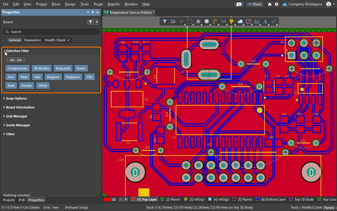
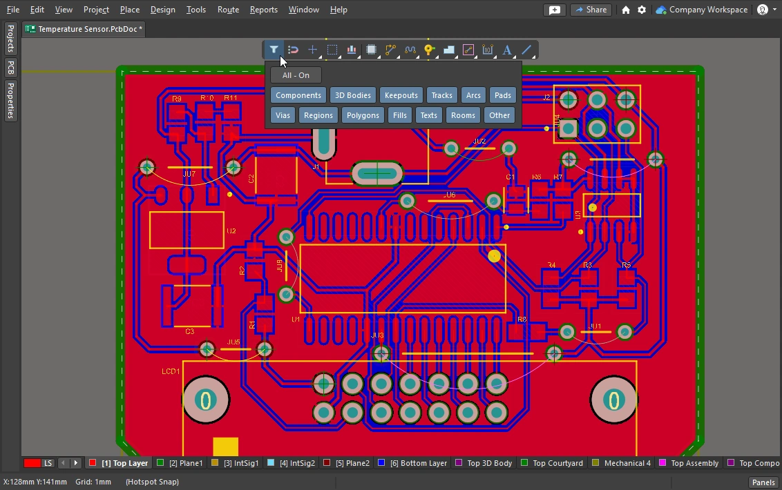
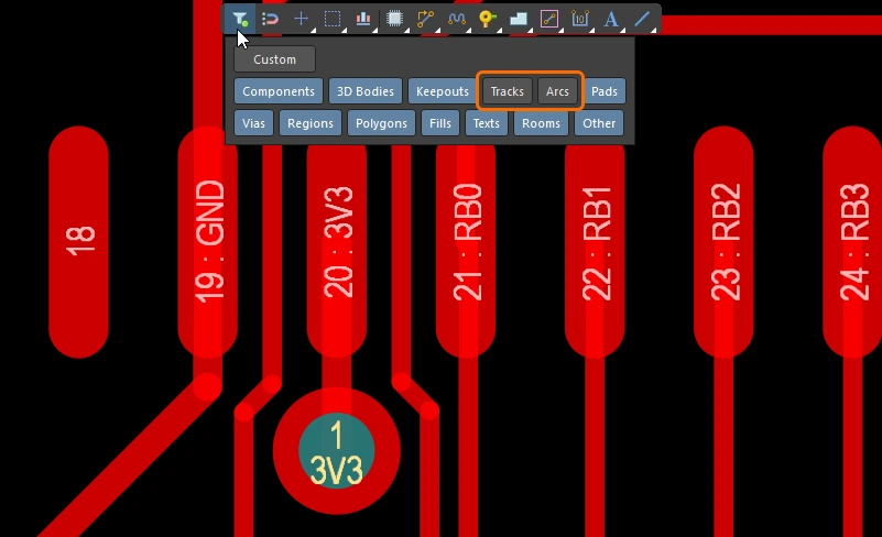
| What can be selected? | All of the graphical editors in Altium Designer include a selection filter. The filter defines what object-types are currently available for selection, it can be accessed in the Properties panel ( Learn more about working with the selection filter and the active bar. |
| Left Mouse Click | Click to select the object under the cursor. If there are multiple objects under the cursor only one will be selected, based on an order of priority. If the mouse is not moved, each subsequent click of the mouse will select the next object in the stack, based on its priority. |
| Selection rectangle – everything touched | Click in free space and drag left, a green selection rectangle is formed ( ). Any object touched by the green rectangle is selected ( ). Any object touched by the green rectangle is selected ( ) (if allowed by the selection filter). ) (if allowed by the selection filter). |
| Selection rectangle – objects within | Click in free space and drag right, a blue selection rectangle is formed ( ). Any object that is completely enclosed by the blue rectangle is selected ( ). Any object that is completely enclosed by the blue rectangle is selected ( ) (if allowed by the selection filter). ) (if allowed by the selection filter). |
| Select a connection line | Alt+Left click and drag left ( ). All visible connection lines that are touched by the green selection rectangle are selected. ). All visible connection lines that are touched by the green selection rectangle are selected. |
| Select existing routes | Left click and drag left ( ). All unlocked track segments that are touched by the green selection rectangle are selected. Use the Tab key to select additional track segments in those nets. ). All unlocked track segments that are touched by the green selection rectangle are selected. Use the Tab key to select additional track segments in those nets. |
| Select routes under a component |
|
| Select component pads | Ctrl+Left click and drag left ( ). All unlocked component pads that are touched by the green selection rectangle are selected. ). All unlocked component pads that are touched by the green selection rectangle are selected. |
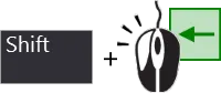
| Adding to the selection | Hold Shift to retain the current selection, while additional objects are selected. |
| Selecting from the PCB panel | If you know the object that you want to select but do not know where it is, the PCB panel can be used to locate and select: nets, differential pairs, components and more. Not only can you select from the panel, you can configure it to zoom to the objects and fade (mask or dim) all other objects ( Learn more about the PCB panel. |
| Accessing all of the selection commands | Select the Edit » Select menu to access all of the PCB editor selection commands ( For example, press |
 )
) ).
). ).
). ).
). ).
).This section summarizes routing selection techniques, learn more about all of the PCB editor object selection commands.
Cleaning and Clearing the Routes
To remove the routing for an entire net you can select it and press Delete – the connectivity engine automatically restores the connection lines. You will also need to selectively remove a section of routing, perhaps un-routing a single physical connection, or removing a number of track segments back to a specific point along the route.

Use the Backspace key to remove a segment and then select the last-touching segment.
 )
) )
)Reroute and Remove Loops
As you route there will be instances where you need to change the path of an existing route. If the path change is complex, it can be more efficient to route a new path rather than sliding the existing routing. This is supported by the Automatic Loop Removal feature.
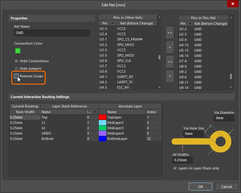
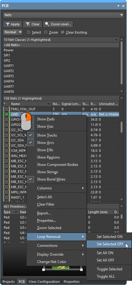
This feature monitors the interactive routing process, and if it detects that a new path has been routed in parallel to an existing path, it automatically removes the old redundant segments. The option is on by default ( ), applying to all nets. It can be disabled for selected nets, or it can be temporarily disabled during interactive routing to allow a specific loop to be created. The loop just created will be retained if loop removal is re-enabled for this net.
Automatic Loop Removal is enabled, when the new route path comes back to meet the existing route the old loop is automatically removed.
 )
) ).
). ).
). ).
).

Moving the Routing
Dragging existing routes is called interactive sliding. The controls for interactive sliding are available in the Preferences dialog ( ), and can also be accessed in the Properties panel by pressing
 Tab during sliding (). During sliding, the interactive routing engine will attempt to maintain the quality of the routing, while complying with the applicable design constraints.
Key features that control the sliding process include: the routing conflict resolution mode (response to obstacles), the gloss strength (effort in tidying the results), and hugging (wrapping around obstacles and forming corners). There are a number of features that support interactive sliding, including T-junction and vertex dragging, via dragging, as well as differential pair dragging support.
A demonstration of interactive sliding being used to modify the existing routing.
Interactive Sliding (Dragging) |
|
| To slide (drag) a track | Click and hold on the track segment, then move the mouse to start sliding the route. The PCB editor will automatically maintain the 45/90 degree angles with connected segments, shortening and lengthening them as required. Interactive sliding also supports non-orthogonal routing. If the route does not move, it could be that the route is locked (an icon appears to indicate this |
| To change the sliding behavior | Press Tab during sliding to access the Properties panel, where you can change any of the interactive sliding settings (). These settings control the track being slid, and also the neighboring tracks that are pushed against during sliding. Configure the sliding options to suit the routing style used on the board - for example, the Hugging Style should be 45 Degree if your routing has diagonal corners. Press the Shift+Spacebar shortcut keys to cycle through the Hugging Style modes during sliding. |
| How the sliding routes are impacted | The extent to which the moving tracks are reshaped as you slide them is controlled by the current Gloss Effort (Routed) setting ( |
How the sliding route responds to existing objects |
During sliding, one of the Routing Conflict Resolution modes (Ignore, Push, HugNPush) applies ( ). Press Shift+R to cycle through the modes as you drag a track segment. ). Press Shift+R to cycle through the modes as you drag a track segment. |
| How neighboring routes are impacted | The impact that the moving tracks have on the adjacent routing is controlled by the current Gloss Effort (Neighbor) setting ( ), press Tab while sliding to change the setting. ), press Tab while sliding to change the setting. |
| Hugging - how glossing wraps around other objects and forms corners | How the glossing engine wraps the route around other objects and forms the corners is referred to as hugging. The available Hugging Style settings include:
|
| Sliding a route corner | The interactive sliding engine includes algorithms specifically for dragging a vertex (corner).
|
| Move a segment instead of dragging | The default behavior is to drag (slide) tracks (selected or unselected). If you need to move a segment without maintaining its connection to the attached segments, either hold Ctrl as you click and drag, or else change the default dragging behavior using either the Unselected via/track or the Selected via/track options in the Preferences dialog (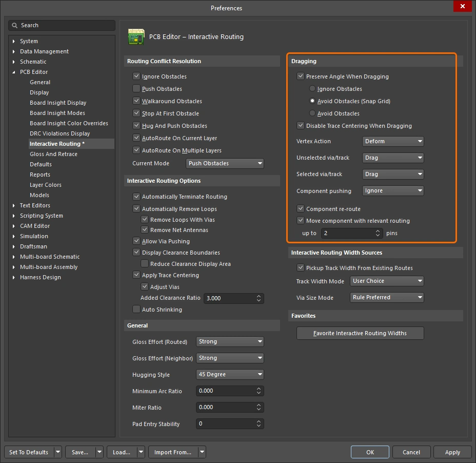 ). ). |
| What you snap to during sliding | The routing you are sliding will not only snap to the current snap grid, but can also snap other objects depending on the object snapping settings, the layer snapping setting, and if the snap guides and axes snapping settings are enabled ( ). To temporarily inhibit snapping during interactive sliding, hold down the Ctrl key. There is a summary of cursor-snap behavior at the start of this page. |
| Modifying T-junctions | There are specific algorithms included to support interactively modifying a T-junction - click and drag on the junction point to modify a T-junction ( ). |
| Dragging a via | Complementing the support for glossing of neighbor routes, via dragging is also supported. Via dragging supports Neighbor Glossing (
). Press Tab during via dragging to access the panel and adjust the settings (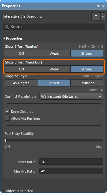 ). ). |
| Dragging a differential pair | To recognize the members in a differential pair, the concept of coupling is used (
). When the software recognizes objects that belong to a differential pair it will attempt to drag the pair's partner track or via if the Keep Coupled option is enabled ( To confirm that the partner objects are coupled, the software checks that the objects:
|
| Push or jump | Existing pads and vias will be jumped, or vias will be pushed if necessary and possible when the Allow Via Pushing option is enabled ( ). ). |
| Break a track segment | To break a single track segment, select the segment first, then position the cursor over the center vertex and click and drag, adding in new segments. |
| Object visibility | To more easily see the objects that make up the current routing, adjust the Transparency of the routing objects in the View Configuration panel (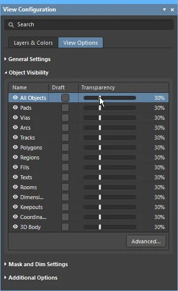 ). ). |
 )
) ).
).Moving a Routed Component
While routing the board it is not uncommon to need to adjust the location of a routed component to create space for additional components and new routing. To help with this, the PCB editor includes a routing-aware move component feature.
There are two aspects to this tool, one is that it attempts to restore the routing to the component pads to suit the new location. The second is that it identifies fanouts, escape routes, and between-pin routes - collectively referred to as relevant routing - and can attempt to exactly maintain the pattern of this routing during the component move (if enabled).
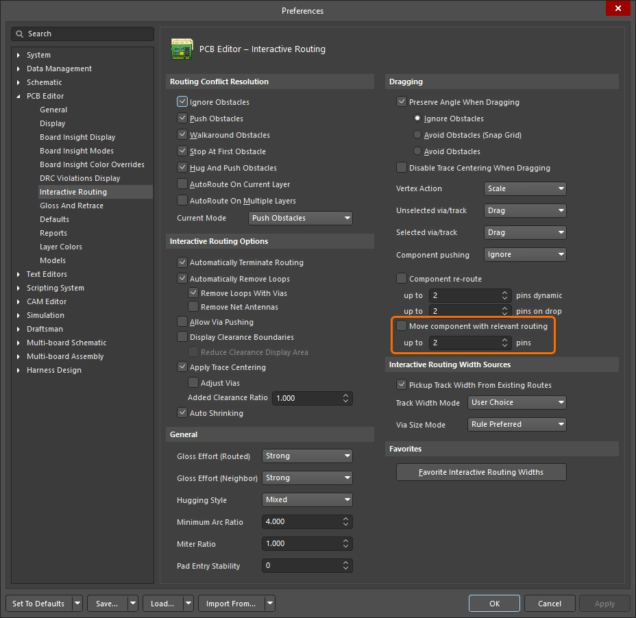
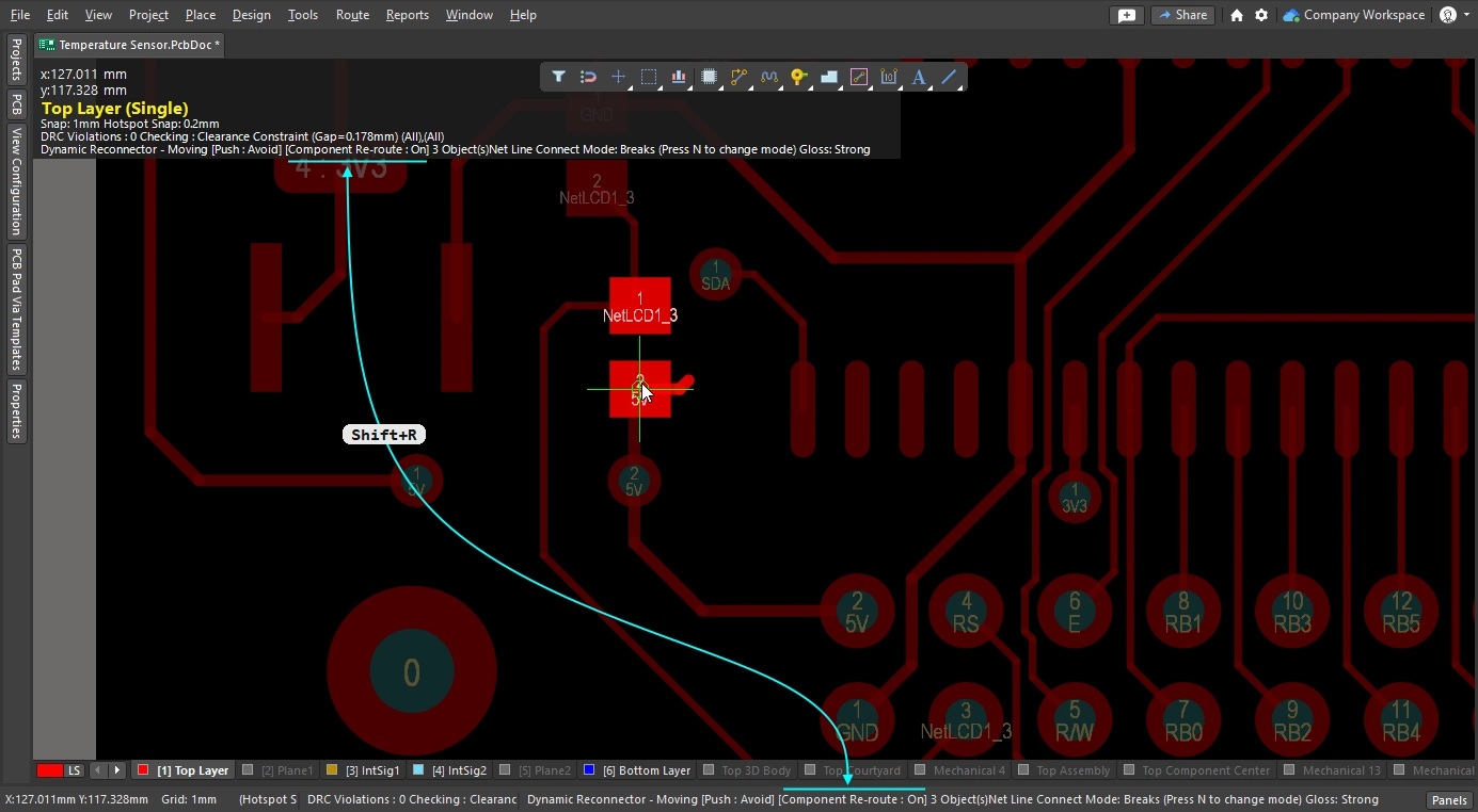
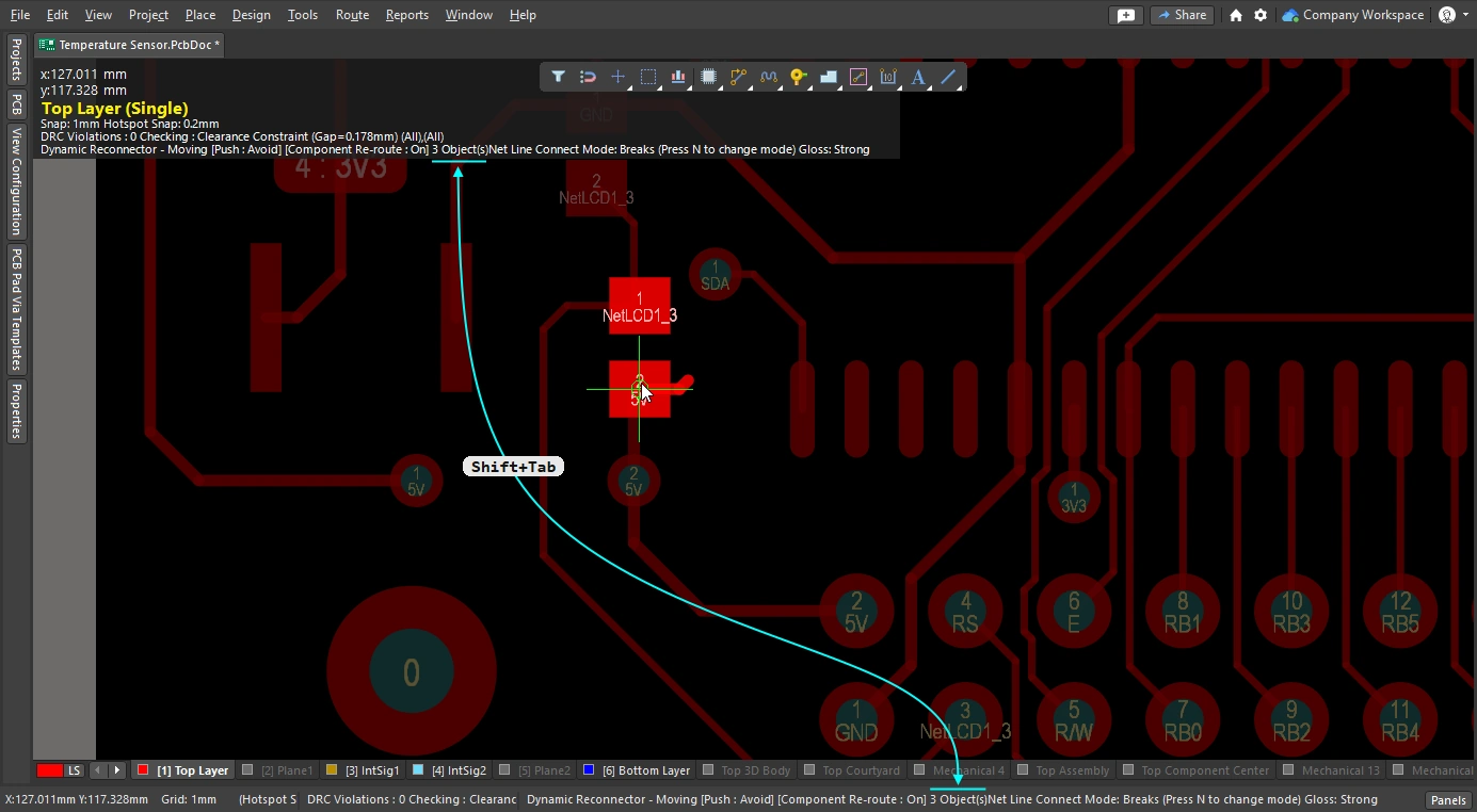
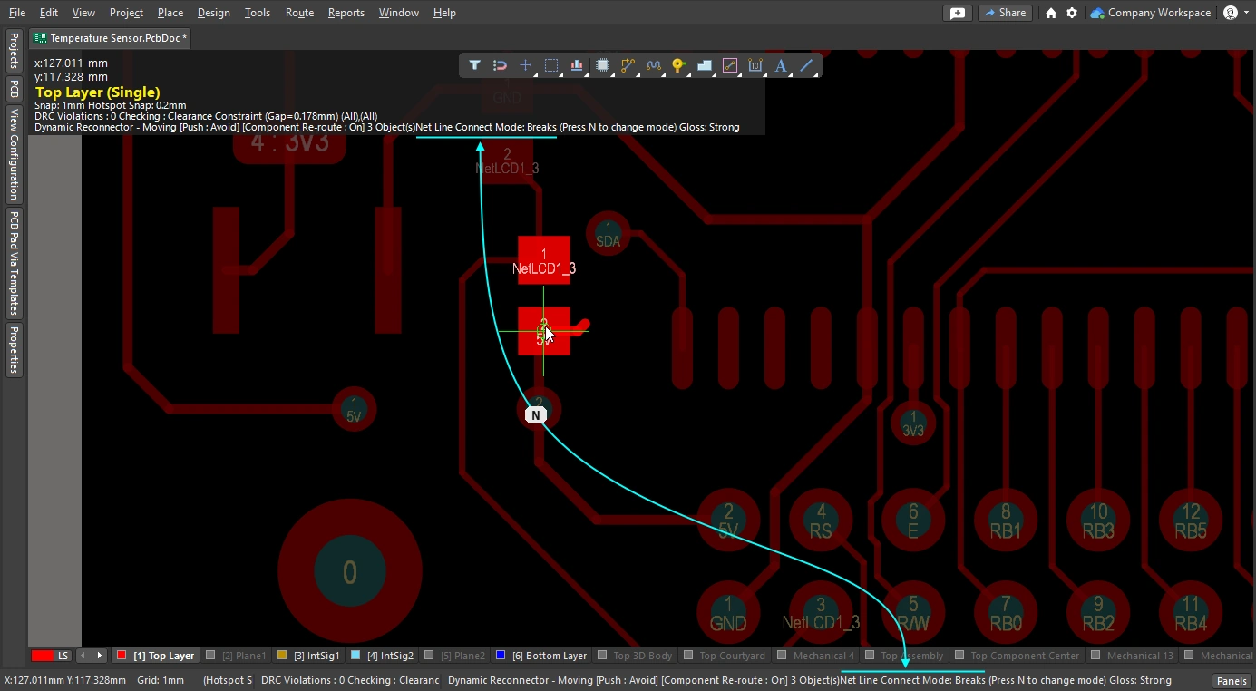
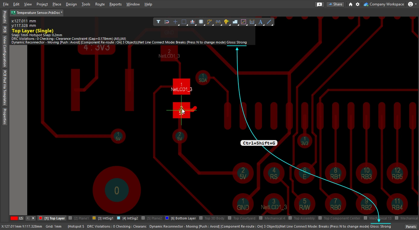
When the Component re-route option is enabled, connected routes are restored after the moving component is placed.
Reroute a Moved Component |
|
| Enable rerouting of moved component(s) | Enable the Component re-route option in the Preferences dialog (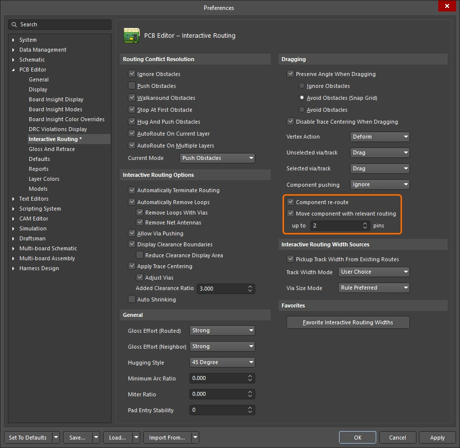 ), or use the ), or use the Shift+R shortcut to toggle it on during a move. The feature supports multiple components being moved in a single action. |
| When does rerouting happen? | Essentially, the feature breaks the routing at the component pads, fanouts or escape routes and then attempt to re-route those broken connections once the moving component(s) has been placed. |
| Include relevant routing | Fanouts, escape routes, and between-pin routes are collectively referred to as relevant routing. These can be moved as if they were part of the component footprint by enabling the Move component with relevant routing option ( |
 ).
).The slides below show how to control each function of the move component with routing feature.
Glossing and Retracing Existing Routes
A core element in the interactive routing engine are the glossing algorithms. Glossing carefully analyzes the routes, reducing the number of corners, and neatening and shortening them. Glossing occurs during interactive routing, as you move the cursor during a route the proposed route path is constantly being glossed. Glossing also occurs during interactive sliding, as you drag an existing route it is constantly being glossed, along with any neighboring route that is impacted by the moving route. Glossing can also be performed as a post process, on any set of selected nets. How strongly the routing is glossed is determined by the current gloss strength.
This section focuses on glossing as a post process, glossing existing routes. Once the routes of interest have been selected, configure the gloss settings in the Gloss and Retrace panel ( ) and then run the Route » Gloss Selected command.
The Glossing engine also includes a retrace feature. Use this when you need to update selected routes to suit changes you have made to the design constraints, such the routing width, or the differential pair gap. With retrace you can "fatten up" that existing power routing, or update that differential pair to new width and gap settings.
-
Glossing focuses on improving the trace geometry while preserving the existing trace width and differential pair gap.
-
Retrace focuses on satisfying the design constraints, updating the widths and differential pair gaps to suit the current constraint settings.
Notes about the Glossing Selected Command
| What does Gloss Selected do? | Glossing analyzes the selected routes, reducing the number of corners, and neatening and shortening them. It also repairs poor quality pad entries, and also attempts to improve the quality of differential pair routing. |
| What is Glossed? |
|
| What options control Gloss Selected? | Gloss Selected obeys the current settings configured in the PCB Editor - Gloss and Retrace page of the Preferences dialog ( |
| Glossing a differential pair |
|
| Support for room-based rules |
|
| Support for Subnet Jumpers | Gloss treats Subnet Jumper tracks as fixed. |
| Exclusions |
|
| Gloss Selected feedback |
|

Notes about the Retrace Selected Command
| What does Retrace Selected do? |
|
| What is Retraced? |
|
| What options control Retrace Selected? | Retrace obeys the current settings configured in the PCB Editor - Gloss And Retrace of the Preferences dialog or in the Gloss And Retrace panel. |
| Updating the vias in Retraced routes | Retrace updates the widths of tracks and arcs according to the applicable Routing Width design constraint or the value entered into the Set Width field in the Gloss and Retrace panel. It does not update the routing vias to reflect changes in the Routing Via Style design constraint. To resolve via-size changes:
|
| Retracing a differential pair | Use Retrace to update the diff pair gap:
|
| Retrace feedback |
|
 ).
).Gloss and Retrace Selected Routing Options
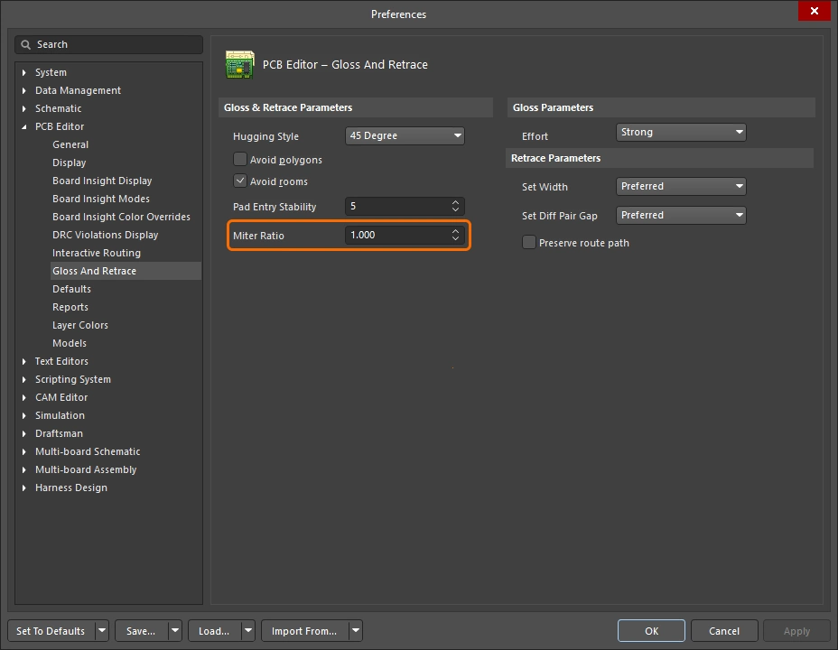
The PCB Editor – Gloss And Retrace page of the Preferences dialog ( ) and the Gloss And Retrace panel () provide numerous controls relating to the functionality of the Gloss Selected and Retrace Selected features within the PCB design space.
Gloss & Retrace Parameters |
|
Hugging Style  |
|
Avoid polygons  |
When enabled, existing polygons will be respected when the Gloss Selected or Retrace Selected command is run. If the option is disabled existing polygons will be ignored (routed across), affected polygons can then be repoured. |
Avoid rooms  |
When enabled, existing rooms will be respected when the Gloss Selected or Retrace Selected command is run. If a room scoped by specific routing width requirements is defined in the design and the routing to be glossed/retraced does not cross the room, the resulting routing will not cross this room either when the option is enabled. If the option is disabled, existing rooms will be routed across, and the width to be used within such rooms will be that is defined in constraints of the room-based rule. |
Pad Entry Stability  |
Protects centered pad entries. Enter the desired level (the preferences) or use the slider bar (the panel) to configure the level of protection. ' |
Miter Ratio  |
Controls the minimum corner tightness. The Miter Ratio multiplied by the current track width equals the separation between walls of the tightest U-shape that can be routed for that ratio. Enter a positive value equal to or greater than zero. |
Effort  |
Select the desired gloss level from the following choices:
|
Set Width  |
Use the drop-down to select one of the rule-based width options (Min / Max / Preferred) of an applicable Width or Differential Pairs Routing design constraint when the Retrace Selected command is run, or retrace using the Current width. Alternatively, enter a desired custom width value directly in the field. |
Set Diff Pair Gap  |
Use the drop-down to select one of the rule-based gap options (Min / Max / Preferred) of an applicable Differential Pairs Routing design constraint when the Retrace Selected command is run, or retrace using the Current gap between the differential pair tracks. Alternatively, enter a desired custom gap value directly in the field. Note that this option is available only when the 45 Degree option is selected for Hugging Style. |
Preserve route path  |
Enable to preserve the exact trace geometry during Retrace. When this option is enabled, the Retrace algorithms will not modify the centerline of the trace. Tracks may change width and be split into segments of different widths, but the trajectory will not be changed. |
Information and Warning Messages
Information Messages ( |
|
Skipped immovable + <Descriptor> |
An object is protected from Gloss/Retrace: for example, locked or belonging to a component. Max count 20, clickable. |
Skipped subnet jumper + <Descriptor> |
Subnet jumpers are left alone, user informed in each case. Max count 20, clickable. |
Skipped reflex angle + <Descriptor> |
Arcs greater than 180 degrees are not glossed. Max count 20, clickable. |
Skipped objects in user-defined Union |
Objects belonging to a union are not glossed (does not apply to Length Tuning unions). Issued once per union involved. Max count 20, clickable, zooming to the Union bounding rectangle. |
Command does not apply to arcs (Retrace only) |
Retrace does not support arcs. Max count 1, clickable, zoom to the first arc encountered. |
 )
)Warning Messages |
|
Applicable Diff Pair Routing rule not found for some object(s) + <Descriptor> |
Some of the Gloss / Retrace targets belong to a diff pair net, but there is no applicable Diff Pair Routing rule. In such cases, the command treats the target as a non-diff pair object, meaning the two sides of the pair may be Glossed away from each other. Max count 1, clickable. |
Applicable Width rule not found for some object(s) + <Descriptor> |
Retrace uses Min to Preferred Width rule settings. If there is no applicable Width rule found, the current width is preserved. Max count 1, clickable. |
Pre-existing Min Width violation(s) detected + <Descriptor> |
Retrace uses Min to Preferred Width rule settings, using preferred if it causes no DRC violations, or smaller if needed to avoid DRC violations. Thus, a DRC-free track will stay DRC-free if it was at least at Min Width to begin with. If it was narrower, setting it to Min width may result in a DRC violation. This message warns of such occurrences, whether or not it resulted in an actual DRC violation. Note that the original thin object will have been widened and possibly moved by the time you have a chance to click on the message. You may need to Undo to understand what has happened. Max count 1, clickable. |
Interactive Routing and Interactive Sliding Options
Whether you're interactively routing a new connection, or dragging (sliding) an existing route to make room for more routing, many of the same routing technologies are applied. This section summarizes: the Interactive Routing ( ), Interactive Sliding (), and Interactive Via Dragging (
 ) options available in the Properties panel. The default settings for these capabilities are configured in the PCB Editor section of the Preferences dialog (
 ).
).
Conflict Resolution 


This option determines how you want the routing/sliding objects to react when they encounter an existing object. Press the Shift+R shortcut to cycle through the available modes during routing or sliding, or press Tab to open the Properties panel and select the required setting.
More about the conflict resolution mode during interactive routing, or during interactive sliding.
| Ignore Obstacles | In this mode the interactive router can place tracks anywhere, including over existing objects, displaying but allowing potential violations. |
| Walkaround Obstacles | Attempt to find a path, from the last click location to the current cursor location, around existing objects such as tracks, pads and vias. The clearance to other objects is defined by the applicable Clearance design rule. If this mode cannot walkaround an obstacle without causing violation, an indicator appears to show the route is blocked. |
| Push Obstacles | Push existing tracks and vias to make room for the new route. If this mode cannot push an obstacle without causing violation, an indicator appears to show the route is blocked. Via pushing is controlled by the Allow Via Pushing option. |
| HugNPush Obstacles | The routing will closely follow existing objects and only push them when there is insufficient room for the track being routed. If this mode cannot hug or push an obstacle without causing violation, an indicator appears to show the route is blocked. |
| Stop at First Obstacle | The routing will stop at the first obstacle that gets in the way. |
| Autoroute Current Layer | Apply auto-router intelligence to the interactive router, automatically selecting between pushing and walking around to give the shortest overall route length, on the current layer. |
| Autoroute MultiLayer | Apply auto-router intelligence to the interactive router, automatically selecting between pushing, walking around or switching layers to give the shortest overall route length. |
Corner Style 
During interactive routing, the shape formed by the tracks and arcs that create a corner is referred to as the corner style. Diagonal corners are the most common, but curved corners (created by placing arcs), are also popular.
Press Shift+Spacebar to cycle through the 5 corner styles during interactive routing (sliding), and press Spacebar to toggle the corner direction, or press Tab to open the Properties panel.
More about controlling the corner style during interactive routing, or during interactive sliding.
Track 45 |
Create the corner using a 45 degree track (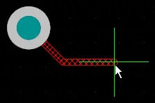 ). Press ). Press Spacebar to toggle the corner direction (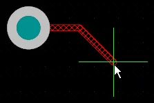 ). ). |
Track 45 with Arc |
Create the corner using a track and an arc of 45 degrees (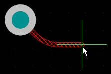 ). Press ). Press Spacebar to toggle the corner direction (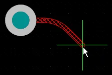 ). Use the ). Use the , & . keys to interactively change the arc radius, hold Shift to accelerate the radius change. |
Track 90 |
Create the corner using two tracks at 90 degrees to each other ( ). Press ). Press Spacebar to toggle the corner direction ( ). ). |
Track 90 with Arc |
Create a corner using a track and an arc of 90 degrees (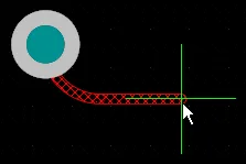 ). Press ). Press Spacebar to toggle the corner direction ( ). Use the ). Use the , & . keys to interactively change the arc radius, hold Shift to accelerate the radius change. |
Any Angle |
Place the next segment directly from the last placed segment to the current cursor position ( ). Use this mode in conjunction with Strong Glossing to perform snake routing. ). Use this mode in conjunction with Strong Glossing to perform snake routing. |
Gloss Effort (Routed) 


During a route event, such as interactive routing or interactive sliding, the software runs the glossing engine. The glossing engine constantly reviews all of the segments placed or impacted by the current route event, attempting to improve the quality of the results. The amount of effort applied is called the Gloss Effort.
Measures of glossing quality include: reducing the number of corners, reducing the number of segments, removing acute angles and reducing the overall route length. Use the Ctrl+Shift+G shortcut to cycle through the settings during interactive routing or interactive sliding, or press Tab to open the Properties panel and select the required setting.
More about gloss effort during interactive routing, during interactive sliding, and during glossing or retracing of selected routing.
| Off | In this mode, glossing is essentially disabled. Note, however, that cleanup is still run after routing/dragging occurs to eliminate, for example, overlapping track segments. This mode is typically useful at the end stage of board layout when the ultimate level of fine-tuning is required (for example, when manually dragging tracks, cleaning pad entries, etc.). |
| Weak | A low level of glossing is applied with the Interactive Router considering only those tracks directly connected to or in the area of the tracks that you are currently routing (or tracks/vias being dragged). This mode of glossing is typically useful for fine-tuning track layout or when dealing with critical routes. |
| Strong | A high level of glossing is applied with the Interactive Router looking for shortest paths, smoothing out tracks, etc. This mode of glossing is typically useful in the early stages of the layout process when the aim is to get a good amount of the board routed quickly. |
During interactive sliding, glossing is temporarily reduced to Weak, to avoid the glossing engine from fighting the designer in their attempts to relocate the routing.
Gloss Effort (Neighbor) 
Gloss Effort (Neighbor) configures the amount of glossing applied to adjacent routes that are impacted by the current interactive routing or sliding. It also has three settings; Off, Weak and Strong.
Press Tab to open the Properties panel and select the required setting.
More about gloss effort during interactive routing and during interactive sliding.
| Off | In this mode, glossing is essentially disabled. Note, however, that cleanup is still run after routing/dragging occurs to eliminate, for example, overlapping track segments. This mode is typically useful at the end stage of board layout when the ultimate level of fine-tuning is required (for example, when manually dragging tracks, cleaning pad entries, etc.). |
| Weak | A low level of glossing is applied with the Interactive Router considering only those tracks directly connected to or in the area of the tracks that you are currently routing (or tracks/vias being dragged). This mode of glossing is typically useful for fine-tuning track layout or when dealing with critical routes. |
| Strong | A high level of glossing is applied with the Interactive Router looking for shortest paths, smoothing out tracks, etc. This mode of glossing is typically useful in the early stages of the layout process when the aim is to get a good amount of the board routed quickly. |
Hugging Style 


This option controls how corner shapes are to be managed during interactive sliding and will affect both the tracks being slid and the tracks being pushed. Existing corners that are impacted by track movement during interactive sliding, will be converted (45 Degree to Rounded, or Rounded to 45 Degree) based on the current Hugging Style. The current Hugging Style is also applied during glossing or retracing of selected routes.
Use the Shift+Spacebar shortcut to cycle through the three modes.
More about hugging during interactive sliding, and during glossing or retracing of selected routing.
| 45 Degree | Always use straight orthogonal/diagonal segments to create corners during sliding (use this mode for traditional orthogonal/diagonal routing behavior). |
| Mixed | Use straight track segments when the objects being moved/pushed against are straight, use arcs when they are curved. The minimum arc size is controlled by the Min Arc Ratio option. |
| Rounded | Use arcs at each vertex involved in the move/push. Use this mode for snake routing, and to use arcs + any angle routes when glossing (during interactive routing and manual glossing). |
Vertex Action 

Options that are applied when you click and drag on a vertex rather than along a track or arc segment (the vertex is the corner location where two segments meet). Use the Spacebar shortcut to cycle through the available modes during sliding.
Other Routing Options
If there is a shortcut available for an option, it is detailed on the right-hand side of the Properties panel. Each description includes an image of where that option can be configured.
When the current connection being routed reaches the target pad, automatically stop routing that net but remain in the Interactive Routing command, ready to click and start routing another net. |
|
When this option is enabled you can route a new path for an existing route, when the new route path comes back to meet the existing path the redundant loop is automatically removed. |
|
| ↳ Remove Loops with Vias | When there is a direct via-to-pad connection, the via will be removed if deemed no longer needed after loop removal. |
| ↳ Remove Net Antennas | A net antenna is a section of routing that is unterminated at one end. These are automatically removed if the current routing impacts on an object that the antenna is touching. |
Keep Coupled |
Check this option to ensure objects that belong to a differential pair will be dragged with the pair's partner track or via. |
Include Miters |
Check this option to include miters while dragging track segments. |
Merge Parallel |
Check this option to allow a track segment being dragged to be merged with an existing stationary segment once the dragged segment became aligned to the stationary segment. |
| Check this option to allow pushing a Via when in Push Obstacles or HugNPush Obstacles modes. | |
Pin Swapping |
Check this option to enable pin swapping for this net. Learn more about setting up for pin swapping. |
Check this option to automatically shrink the routing width to a value that would allow routing in locations where the track cannot be routed between obstacles with the currently chosen routing width. Note that the width can be reduced down to the minimum allowed by the applicable Routing Width design constraint. |
|
Display the no-go area around existing objects ( |
|
| ↳ Reduce Clearance Display Area | Reduce the display of clearance boundaries to a circular zone around the current cursor location ( |
The length gauge indicates how well the current route is meeting applicable Length and Matched Length design rules. Learn more about Length Tuning. |
|
The slider protects centered pad entries, preventing Glossing from un-centering a centered track (it holds a centered track on-center, it does not center an un-centered track). Use the slider bar to configure the level of protection. |
|
When enabled, the interactive routing engine detects when a route is passing between pads and attempts to center the route, up to a maximum distance of the applicable clearance constraint multiplied by the Added Clearance Ratio specified below. Trace centering can also be applied between via-via and via-pad if the Adjust Vias sub-option is enabled. This feature can be disabled during track sliding, if required. |
|
This option serves two purposes:
To exclude vias disable the Adjust Vias option. |
|
A multiplier of the applicable clearance, which is then added to the clearance. For example, if the applicable clearance is |
|
Enable this option to switch off trace centering when interactively sliding a route. When this option is enabled, trace centering does not apply during interactive sliding of a route, even if the main Apply Trace Centering option is enabled. |
|
The Miter Ratio controls the minimum corner tightness. The Miter Ratio multiplied by the current track width equals the separation between walls of the tightest U-shape that can be routed for that ratio ( |
|
The Min Arc Ratio is applied during any angle interactive routing and also during interactive sliding with Mixed Hugging Style. The ratio is used to determine the minimum radius arc allowed, when the arc radius falls below this minimum the arc is replaced by track segments, where:
|
|
To support pin swapping at any stage of the design process, including on the routed PCB, the PCB editor can add and remove small routing connectors into swap-enabled nets, called subnet jumpers. A subnet jumper is a short segment of track that the software recognizes as an element that can be easily placed and removed; either manually via the Add and Remove Subnet Jumper commands in the Route menu, or automatically by the routing engine if you route to a swappable pin during interactive routing. This value defines the length of the subnet jumper that is added to a swappable net during interactive routing. |


Net / Differential Pair Information 

During interactive routing/sliding and differential pair routing/sliding, the net(s) under edit are detailed at the top of the Properties panel.
Name & Class |
The Name of the Net or Differential Pair under edit is displayed, along with the Class it belongs to (if any). The Name and Class are live links, click to open the PCB panel displaying the relevant net or pair details. |
Length & Delay |
The Signal Length and the calculated Delay are detailed, the displayed values are valid when the initial routing/sliding click occurs. The Length and Delay are live links, click to open the PCB panel displaying the relevant net or pair details, which will update in real-time as the routing or sliding is performed. |
Routing Properties 

During interactive routing, the properties of the route objects can be edited in the Properties panel.
| Layer | The layer that the multi-route is being placed on. Use the drop-down to select a different layer, vias will be added automatically. Alternatively, use the layer-change shortcuts. |
| Gap | If the current route is a differential pair the Gap option is displayed, used the dropdown to set the routing gap to the Min/Preferred/Max value defined in the applicable differential pair routing constraint. Learn more about differential pair routing. |
| Via Template | If the constraint that defines the via being placed has the Template Preferred option enabled ( If the constraint that defines the via being placed has the Min/Max Preferred option enabled ( Learn more about pad and via templates. |
| Via Hole Size | Displays the via hole size that will be used. The value can be edited directly, within the range allowed by the applicable routing via style design constraint. More about selecting the via size and via type during routing. |
| Via Diameter | Displays the via diameter that will be used. The value can be edited directly, within the range allowed by the applicable routing via style design constraint. More about selecting the via size and via type during routing. |
| Width | When you click to start routing from an existing route, the default behavior is to routing using the same width. Use the dropdown to set the routing width to the Min/Preferred/Max value defined in the applicable routing width constraint. |
 )
) )
)Applicable Design Constraints (Rules) 
During interactive/differential pair routing, the Routing Width and Routing Via Style design constraints that apply to the route being performed, are displayed in the Properties panel. These are live links, click to open the relevant design constraint for review or editing, if required.
Via Constraint |
The Routing Via Style design constraint that is applicable to the net(s) currently being routed. |
Width Constraint |
The Routing Width design constraint that is applicable to the net(s) currently being routed. |
Dragging options
Defines the behavior to be applied when you click and drag on an object.
| Preserve Angle When Dragging | When enabled the software will attempt to preserve the angle when dragging, in accordance with the current Interactive Sliding settings in the Properties panel (
|
| Disable Trace Centering When Dragging | |
| Vertex Actions | Detailed earlier on this page |
| Unselected via/track | Defines the default behavior when dragging an unselected via or track to be either a Move or Drag action. To access the mode not chosen, hold the |
| Selected via/track | Defines the default behavior when dragging a selected via or track to be either a Move or Drag action. To access the mode not chosen, hold the Ctrl shortcut as you click and hold on the via or track. |
| Component pushing | This field defines the current Component Conflict Resolution mode when moving components within the design space. For this feature, components are identified by their selection bounding box. The following modes are supported:
|
| Component re-route | When enabled, after moving component(s) to a new location and releasing, the software will attempt to re-route the component(s) to reconnect any broken nets. During movement, the Shift+R shortcut can be used to toggle the re-route behavior off/on. Note that component re-routing is not applied to a moved component if that component is a member of a union. |
| Move component with relevant routing | Enable this option to start the move component action with the relevant routing (Components +Via Fanouts +Escapes +Interconnects). Use the Shift+Tab shortcut to cycle the selection set. Disable the option to start the move component action with components only selected. Because the set of relevant routing objects is detected prior to the move commencing, it is not possible to use Shift+Tab to cycle through the selection set when the option is disabled.
|
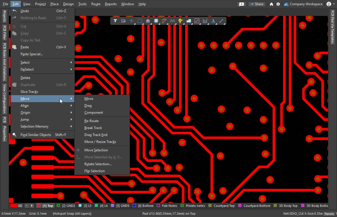 )
)Interactive Routing Width Source options 
Stores the last-used routing width and via size selected during interactive routing. During interactive routing, cycle though the modes by pressing the 3 shortcut.
| Pickup Track Width From Existing Routes | If enabled, the interactive router will set the width of the new route to match the track under the cursor when you click to commence interactive routing, instead of using the Track Width Mode selected below. If there is no track segment below the click location when you commence interactive routing, then the current Track Width Mode is used. |
| Track Width Mode | There are four possible widths that a connection can be routed at: Constraint Minimum, Constraint Preferred, Constraint Maximum, and User. This option holds the last-selected mode, which is used the next time you launch the Interactive Routing command. Press the |
| Via Size Mode | There are four possible via sizes that can be used for a layer change during interactive routing: Constraint Minimum, Constraint Preferred, Constraint Maximum, and User. This option holds the last-selected mode, which is used the next time you launch the Interactive Routing command. Press the More about selecting the via size and via type during routing. |
Favorite Width options 
Stores the user-defined list of routing widths that are presented when the Shift+W shortcut is pressed during interactive routing ( ).
).
| Favorite Interactive Routing Widths | Click the button to open the Favorite Interactive Routing Widths dialog, where you configure the list of pre-defined widths that the Shift+W shortcut displays during interactive routing. |