
Fusion 360 CoDesigner

CircuitMakerとAutodesk Fusion 360間での設計変更の受け渡し
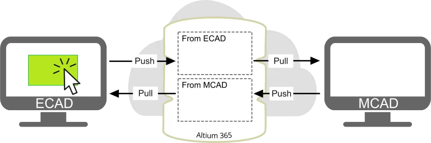
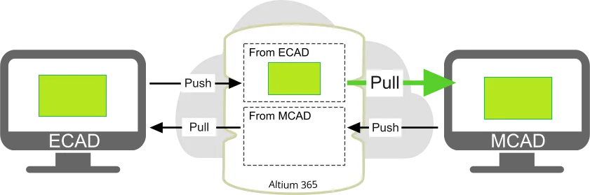
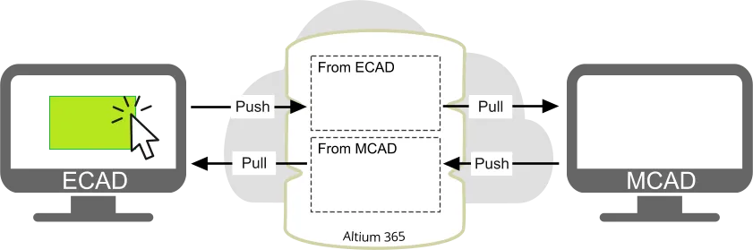
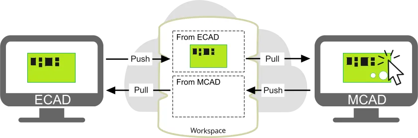
CoDesignerは、機械的なPCBアセンブリをAltium 365プラットフォームを介してECADに転送します。Push/Pullされる変更は方向性があり、MCADからPush(ECADへPull)されたPCBアセンブリは、ECADからPush(MCADへPull)されたPCBアセンブリとはAltium 365プラットフォーム上で別々に保存されます。
 ECADとMCADの変更は、Altium 365プラットフォーム上で個別に保存されます。
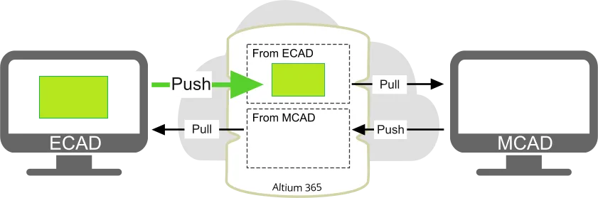
Push
どちらの環境で作成された設計変更も、ソースエディタで


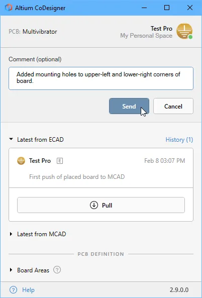
送信
- 変更されたPCBファイルの作業コピーが未保存の場合は自動的に保存されます。
- 変更内容がAltium 365プラットフォームに書き込まれます。
-
コメントはソースエディタの
CoDesigner パネルのメッセージスレッドに表示されます。 - ターゲットエディタのパネルには、次回設計ファイルの作業コピーを開いた際に変更が保留中である旨のメッセージが表示されます(下図右参照)。
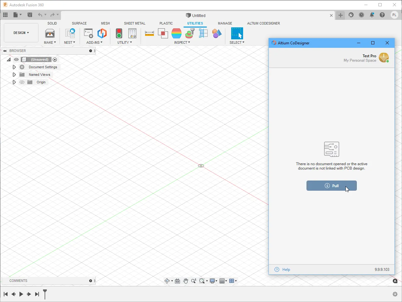
Pull
いつでも変更が保留中かどうかを確認するには、
-
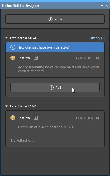
変更が保留中の場合、
New changes have been detected というメッセージがCircuitMakerのFusion 360 CoDesigner パネル、またはFusion 360のAltium CoDesigner パネルに表示されます(上図参照)。 -
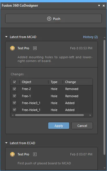
Pull ボタンをクリックすると、Changes のリストが表示されます(下図参照)。各変更は、PCBファイル内のデータとソースエディタからPushされたデータの差分です。 -
受け入れたい変更ごとにチェックボックス(
 )を有効にします。
Changes のリスト上で右クリックすると、すべての変更を有効または無効にできるコンテキストメニューにアクセスできます。 -
Apply ボタンをクリックして、これらの変更をPCBに適用します。
CircuitMakerとAutodesk Fusion 360を異なるユーザーで作業する場合
電子設計と機械設計の両方を担当するエンジニアの場合は、CircuitMakerとFusion 360の両方からAltium Liveにサインインします。各設計ツールで異なるエンジニアが作業する場合は、プロセスが少し異なります。この場合、CircuitMakerのエンジニアがFusion 360のエンジニアとプロジェクトを共有する必要があります。
異なるエンジニアでCoDesignerを使用するには:
- CircuitMakerエンジニアとFusion 360エンジニアの両方が自分自身のAltium Liveアカウントを持ち、それぞれでCoDesignerにサインインする必要があります。
-
プロジェクトはCircuitMakerエンジニアのPersonal Spaceに保存されているため、CircuitMakerエンジニアが
Share プロジェクトをFusion 360エンジニアと共有する必要があります。特定のユーザーとプロジェクトを共有する方法について詳しくはこちら。
► CircuitMakerでのプロジェクト作業について詳しくはこちら。
Autodesk Fusion 360でのCoDesignerのインストールと設定
Autodesk Fusion 360と連携するには、
Add-Inのインストール方法:
- インストール前にAutodesk Fusion 360を閉じてください。
- Fusion 360 Add-In(AltiumCoDesignerFusion360_<VersionNo>.exe)をダウンロードしてインストールします。
-
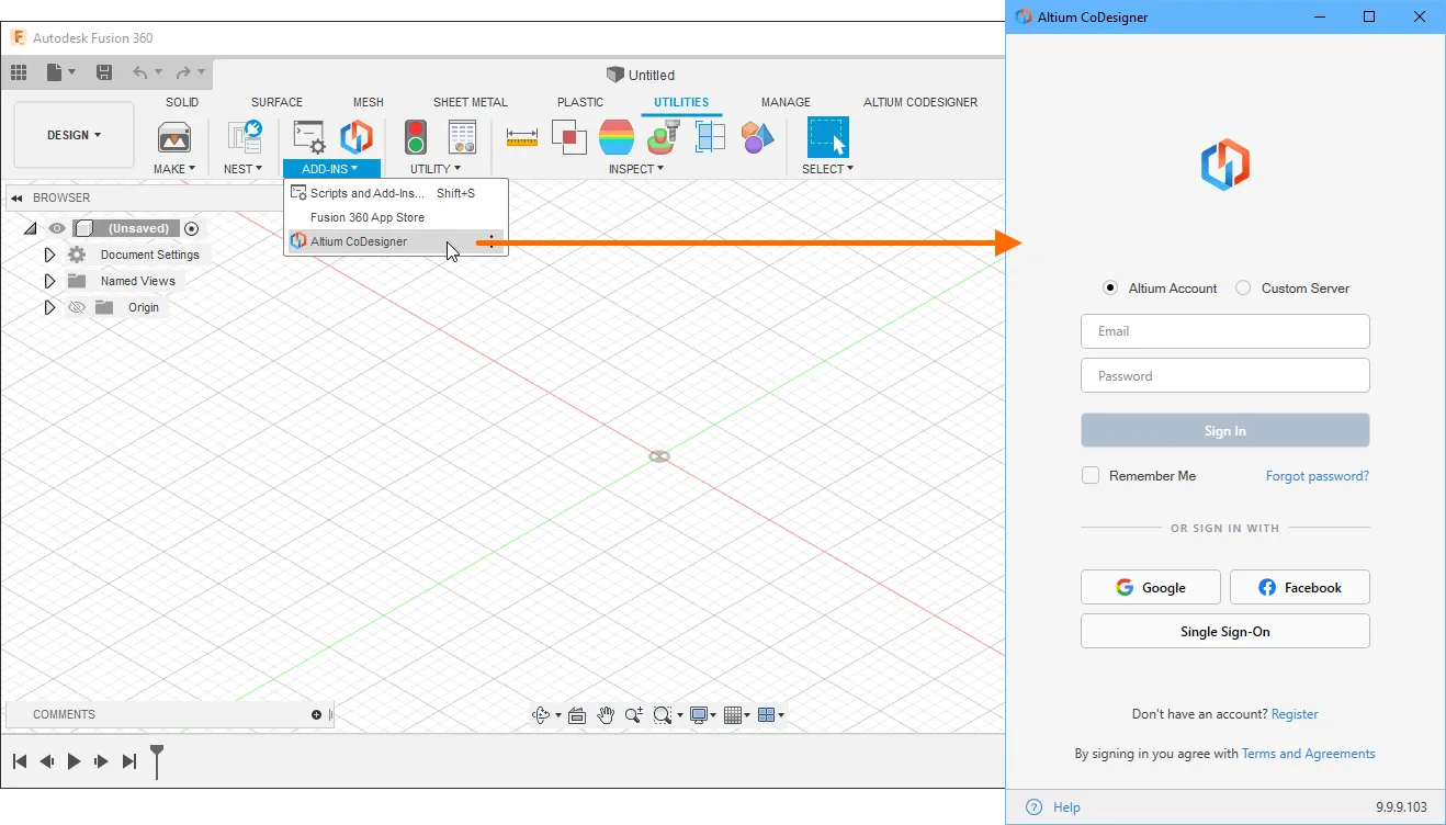
Autodesk Fusion 360を起動し、Add-Inが
Add-Ins セクションのTools リボンにインストールされていることを確認してください(下図参照)。 -
CoDesigner Add-Inは、Autodesk Fusion 360に
Altium CoDesigner パネルを追加します。すべてのコラボレーション作業はこのパネルを通じて行われます。
CoDesignerパネルの表示
Autodesk Fusion 360では、
Autodesk Fusion 360でAltium 365プラットフォームに接続する
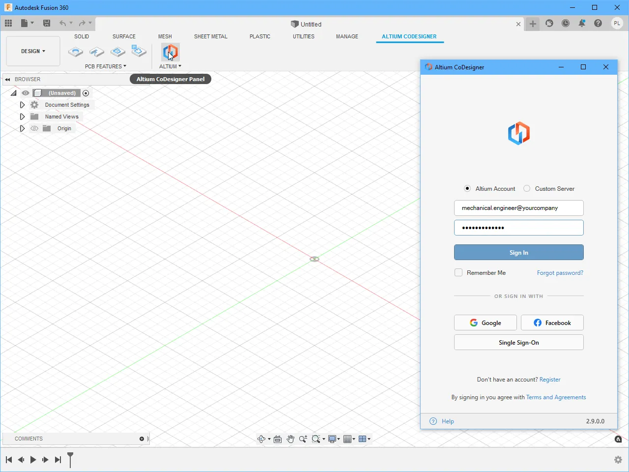
Autodesk Fusion 360はAltium 365プラットフォームを介してCircuitMakerと連携します。初回利用時にはサインインが必要です。
サインインしていない場合、
-
Altium Account オプションをAltium CoDesigner パネルで選択します。 -
Altium Liveにサインインする際のメールアドレスを
Email 、Altium LiveのPassword を入力します。 -
Remember Me オプションを有効にすると、詳細情報(パスワードを含む)が保持され、Autodesk Fusion 360起動時に自動的にAltium 365プラットフォームへ接続されます。 -
Sign In ボタンをクリックして接続します
サインインが完了したら、Altium CoDesignerを通じたコラボレーションを開始できます。
Fusion 360のコラボレーション設定の構成

サインイン後、CoDesignerの設定は

-
Ignore components smaller than - Fusion 360のパフォーマンスはPCB上の部品数に影響されます。このオプションを使用すると、Pull時に高さが<Value><Units>in height<Value><Units>Height プロパティであり、PCB部品に含まれる3Dモデルの高さではありません。すべての部品を含めるにはこのオプションを0に設定してください。 -
Participate in the product improvement program - このオプションを有効にすると、CoDesignerの利用状況に関する技術情報を自動的にAltiumと共有します。
機械設計者への推奨事項
このセクションでは、CoDesignerを使用する際に機械設計者が知っておくべき機能や動作について説明します。
同期プロセスの管理
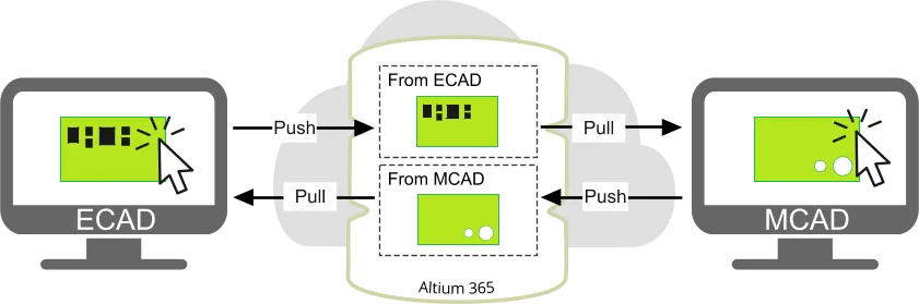
ECADとMCADは、それぞれAltium 365プラットフォーム上の異なる保存場所に変更をPushします。つまり、各エンジニアは他方のエンジニアがPushした変更のみをPullできます。これらの変更には、他方のエンジニアがPushする前に既に受け入れられている自分自身の変更のみが含まれます。
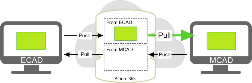
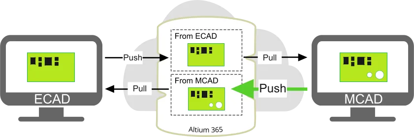
例えば、ECADで基板が作成され、Altium 365プラットフォームにPushされ、MCADにPullされる場合:
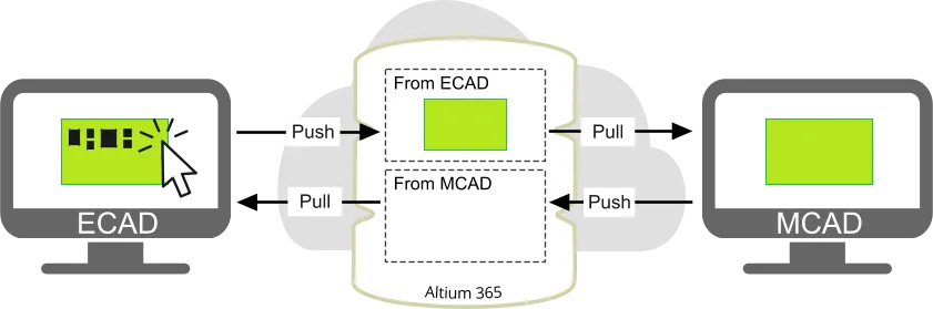
ECADエンジニアが部品を追加し、
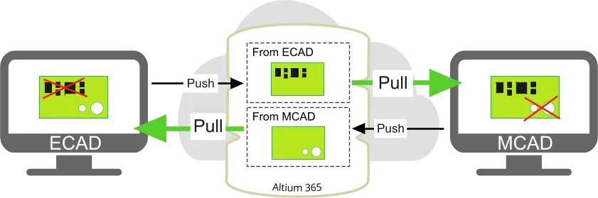
各エンジニアは、提案された変更の中から特定のものを拒否することも可能です。例えば、ECADエンジニアは穴の追加は受け入れ、削除された部品の削除は拒否することができます。しかし、この方法は複雑なボードや変更が多い場合には管理が難しくなります。もう一つのポイントは、デカールへのすべての変更はCoDesignerからは単一の変更としてしか認識されないため、個別にではなく一括でしか受け入れ・拒否ができないことです。
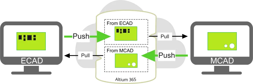
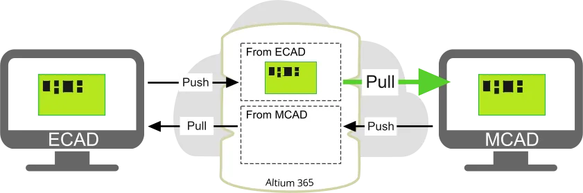
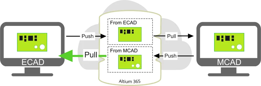
より良い方法は、一方のエンジニアが変更を加えてボードをPushし、もう一方のエンジニアが自分の変更を加える前にボードをPullすることです。下図のように行います:


機械エンジニア間での変更の同期
- CoDesignerは、機械PCBアセンブリをAltium 365プラットフォームを通じてECADに転送します。Push/Pullされる変更は方向性があり、MCADからPush(ECADへPull)されたPCBアセンブリは、ECADからPush(MCADへPull)されたPCBアセンブリとはAltium 365プラットフォーム上で別々に保存されます。つまり、2人目の機械エンジニアは、直前に他の機械エンジニアがAltium 365プラットフォームにPushした修正済みボードをPullすることはできず、最後にPushされたECADデータをPullすることになります。他の機械エンジニアに自分の変更を見せるには、他のアセンブリと同様にPCBアセンブリを共通ストレージに保存してください。この方法でMCADの拘束条件も保持されます。あるいは、ECADデザイナーにデータをCircuitMakerにPullして保存し、更新された設計をMCADにPushし直してもらう方法もあります。ただし、後述の通り、この方法ではMCADの拘束条件は含まれません。
ECADとMCADの変更はAltium 365プラットフォーム上で別々に保存されます。
- MCADの拘束条件は、それが作成されたMCADアセンブリ内にのみ存在します。MCADからECADへボードをPushした場合、拘束条件による部品位置はPushされますが、拘束条件自体はPushされません。そのため、ボードが新しいMCADアセンブリにPullされた場合、以前のMCADエンジニアが作成した拘束条件は含まれません。
- もう一つ重要な点は、異なる機械エンジニアが同じPCBアセンブリに加えた変更は、Pushされた際にマージされず、最後にPushした機械エンジニアの変更が他のエンジニアの変更を上書きすることです。
ECAD側で行われた変更の可視性
MCADソフトウェアでPCBアセンブリ自体を開くことが重要です。PCBアセンブリが開かれていれば、ECAD側から行われPushされた変更が
ECADからPCBアセンブリへの変更の取得
- MCADでPCBアセンブリを別ファイル(ルートアセンブリとして)として開きます。
-
Altium CoDesigner パネルを開きます。 -
Pull をクリックします。 -
テーブルで変更内容を確認し、適用したいものを有効にして
Apply ボタンをクリックします。
MCADで初めてPCBアセンブリを開く場合
- PCBアセンブリをデバイスのアセンブリに追加します。
- 適切なメイト/拘束を適用して固定します。
- ボードパートの編集を開始します。
- ボード押し出しのスケッチを編集し、筐体に合わせて形状を調整します。
MCADでPCB設計を変更する際の注意点
以下は、MCADで使用する設計形状やオブジェクトが、ボードをECADにPushした際にサポートされるようにするためのヒントです。
- ボードパートの編集を開始します。
- ボード押し出しのスケッチを編集します。
-
必要に応じて、機械エンジニアはボード定義の初期段階でベアボードのMCAD原点を変更できます。その場合、ボードパート内でボード外形の
sketch 全体を移動または再描画してください。ボードパートはボードアセンブリ内で「固定」として拘束されており、その原点はアセンブリの原点と一致しています(したがって「MCAD原点」はボードパート原点とボードアセンブリ原点の両方を指します)。この拘束を変更または解除しないことを強く推奨します。予測できない変更が発生する可能性があるためです。
- ボードパートの編集を開始します。
-
ボードパートの上面または下面に
Hole フィーチャーを作成/編集します。
- ボードパートの編集を開始します。
-
ボードパートの上面または下面に基づいて
Extruded Cut フィーチャーを作成/編集します。
- ボードアセンブリの編集を開始します。
- 部品の移動/回転/反転、またはメイト/拘束を行います。
MCADで固定または拘束された状態とECADでロックされた状態の同期
MCADでコンポーネントが固定または拘束されている場合、ECADではそのコンポーネントがロックされます(その拘束がPCBアセンブリ内での移動を許可しているかどうかに関わらず)。ECADでコンポーネントがロックされている場合、MCADではすでに拘束されていない限り固定されます。ロック/固定状態の変更はMCADとECAD間で同期されます。
ECADコンポーネントパラメータのMCADへの転送
ECADのPCBコンポーネントパラメータは、MCADで作成された対応するモデルに転送されます。ただし、もともとMCADで配置されたコンポーネントは含まれませんのでご注意ください。
MCADでの拘束条件および寸法の操作
- 機械設計者は、基板外形の要素から他の基板外形要素、基準/リファレンスフィーチャ、上位アセンブリ内の部品、またはコンポーネントへ拘束を適用できます。CoDesignerはこれらの拘束を変更しません。しかし、ECAD側で基板外形が変更されると、MCADで基板部品のスケッチが再描画され、すべてのエッジIDが変更されます。ECADで基板外形の一部でも変更があると、MCADで基板全体が再描画され、すべての基板エッジIDが変更されることにご注意ください。これらのエッジや派生サーフェスに拘束が適用されていた場合、それらの拘束は失われます。基板自体はMCAD上でその場に残りますが、必要に応じて拘束を手動で復元することができます。ただし、復元には時間がかかるため、基板外形の変更はMCAD側でのみ行うことを推奨します。
- 機械設計者は、コンポーネントから基板、筐体、または他のコンポーネントへの拘束を適用できます。これらの拘束は、該当するコンポーネントのモデルがローカルで見つかる場合(PCBアセンブリが別フォルダで一から構築されていない、またはモデル保存用の共通フォルダが設定されている場合)には維持されます。ただし、ECAD側でコンポーネントが移動された場合、MCAD側での配置変更がその移動と一致しない場合があるため、手動で確認する必要があります(この場合、CoDesignerが通知します)。ECADフットプリントを持つコンポーネントについては、コンポーネントのスタンドオフ(基板表面に対するZ方向の位置)は常にフットプリント内のSTEPモデルの位置によって定義されます。CoDesignerは、MCADへのPull時に競合するMCAD拘束を常に上書きしようとします。
MCADからECADへ転送されない変更
- ・ベアボード厚さ - ECADのレイヤースタックで定義されます。
- 基板部品に追加された幾何学的フィーチャ(例:3D面取り/フィレット)※ただし、基板のZ軸方向の穴や押し出しカットは除く。
- 基板アセンブリのコンテキストで作成された追加の幾何学的フィーチャ(例:アセンブリのコンテキストで作成された穴)、これらのフィーチャが部品に伝播されない限り。
- コンポーネントから独立して移動された場合のコンポーネント穴の位置。
- コンポーネント穴のサイズ。
- フィーチャパターン。
 AI で翻訳