TRANSLATE:
親ページ: ECAD-MCAD 共同設計
AltiumのMCAD CoDesigner技術は、機械設計と電気設計のドメインを接続し、機械工学者と電子工学者がPCBを両ドメイン間で行き来させることを可能にします。
Altium設計ソフトウェアでは、PCBエディタから基板とコンポーネントのデータを読み込み、抽出する拡張機能であるMCAD CoDesigner拡張機能を通じてこれを実現します。MCADソフトウェアでは、Altium CoDesignerアドインが同様の機能を果たし、MCADソフトウェアから基板とコンポーネントのデータを読み込み、抽出します。
ECADとMCADソフトウェアは、Altium Workspaceを介して設計変更を伝達します。これは、Altium 365のクラウド上、またはAltium On-Prem Enterprise Serverを使用して企業ネットワーク上でホストすることができます。Workspaceは橋渡しの役割を果たし、ECADとMCADソフトウェアの両方が接続します。Workspaceは基板とコンポーネントのデータを保持し、ECADとMCADのエンジニアが自律的に作業を続け、準備ができたときに変更をプル(取り込み)およびプッシュ(送信)することを可能にします。
- Altium CoDesignerで利用可能な機能は、Altium Designerソフトウェアサブスクリプションのレベルによって異なります。
- 最新の発表や活発な会話に参加するには、MCAD CoDesignerフォーラムをご覧ください。
- このページには更新が逆順にリストされており、最新の更新はページの上部にあります。
- このページのビデオでは、Altium Designerを使用してCoDesignerの機能をデモンストレーションしています。他のAltium設計クライアントとMCADソフトウェア間の共同設計プロセスは基本的に同じです。
サポートされるバージョン
CoDesignerは継続的に開発されており、このページでは各バージョンで行われた変更を概説しています。CoDesigner拡張機能とアドインは、Altium設計ソフトウェアの更新サイクルとは別に更新することができるため、このページにはAltiumソフトウェアのサポートされるバージョン、およびMCADソフトウェアのサポートされるバージョンに関する情報も含まれています。
TRANSLATE:
ECAD-MCAD バージョン互換性マトリックス
このマトリックスは、ECAD/MCADのバージョン互換性の概要を提供します。各セルの最初の行には、サポートされているAltium DesignerまたはMCAD製品のバージョン番号が詳細に記載されています。2行目には、そのバージョンのAltium DesignerまたはMCAD製品で使用する推奨のExtension/Add-inが記載されています。この情報は、Altium MCAD CoDesignerの各リリースのNew In情報のSupported Versionsセクションにも詳細に記載されています。
|
Altium Designer/
CoD extension
|
Autodesk Fusion®/
MCAD Add-in
|
Autodesk Inventor®/
MCAD Add-in
|
Dassault Systemes SOLIDWORKS®/
MCAD Add-in
|
PTC Creo Parametric®/
MCAD Add-in
|
Siemens® NX™/
MCAD Add-in #
|
- Altium DesignerにインストールされているCoDesigner拡張機能のバージョンを確認するには、Current User InformationメニューからExtensions and Updatesを選択し、MCAD CoDesigner拡張機能のアイコンをクリックします。(画像を表示
![]() )
)
- 表に示されているように、Altium Designerのバージョンに対応するCoDesignerの複数のバージョンがあります。最新の機能と機能にアクセスするために、MCAD CoDesignerの最新バージョンに更新することをお勧めします。Extensions and UpdatesビューのUpdatesタブで更新を確認してください。
- MCADソフトウェアに現在インストールされているCoDesigner Add-Inのバージョン番号は、Altium CoDesignerパネルの下部に詳細が記載されています。(画像を表示
![]() )
)
- 新しいバージョンのMCADソフトウェアがリリースされると、現在サポートされている最も古いバージョンのMCADソフトウェアは開発およびテストプロセスから除外されるため、この互換性マトリックスから削除されます。
- 古いバージョンのMCADは機能する可能性がありますが、検証されていません。
- # Siemens NXの新しいバージョンでは、現在のバージョンと署名されたバージョンの差が大きすぎるという警告が表示されることがあります。Siemens NXはv.2312までテストされており、この警告は無視しても構いません。または、Siemens NXのCustomer DefaultsダイアログでShow Warning when Loadingオプションを無効にすることができます(画像を表示
![]() )。
)。
(Note: The table content was omitted for brevity, but should be translated as well if included in the request.)TRANSLATE:
CoDesigner 3.7.0の新機能
リリース: 2024年2月7日 – Autodesk Fusion 360用バージョン3.7.0ホットフィックス
リリース: 2024年1月26日 – バージョン3.7.0ホットフィックス (MCAD CoDesigner拡張機能がバージョン3.7.0.2033に変更)
リリース: 2024年1月17日 – バージョン3.7.0
主な機能のハイライト
MCAD CoDesignerの3.7アップデートでは、ECADとMCAD間でのカウンターシンクおよびカウンターボア定義の転送がサポートされるようになりました。また、ECADのルートツールパスをMCADに転送し、そこで押し出しカットとして使用するサポートも導入されました。プロジェクトパラメータの転送も改善され、ハーネス定義のサポートも強化されました。Siemens NXを使用するMCADエンジニア向けのECAD-MCADコンポーネントリンクの改善もいくつかあります。
ECADからMCADへのプロジェクトおよびバリアントパラメータの転送
ECADでは、ユーザー定義のパラメータを使用して、設計者が必要な情報を正確な場所に含めることができます。このCoDesignerのアップデートでは、以下の転送がサポートされます:
- ECADプロジェクトレベルのパラメータをMCAD PCBアセンブリに
- ECADバリアントレベルのパラメータを特定のMCAD PCBバリアントアセンブリに 1
- ECADマルチボードアセンブリパラメータをMCADデバイスアセンブリに 2
- ECADハーネスプロジェクトパラメータをMCADハーネスアセンブリに
1 Autodesk Inventorではサポートされていません
2 マルチボードアセンブリは現在、CoDesigner for SOLIDWORKSおよびPTC Creoでサポートされています。
 ECADパラメータは、ボード、バリアント、ハーネス、マルチボードアセンブリのMCADプロパティに転送されるようになりました。
カウンターシンクおよびカウンターボアホールをMCADに転送
CoDesignerは現在、カウンターシンクおよびカウンターボアホールをECADとMCADの間で双方向に同期します。MCADで3D Copperオプションが有効になっている場合、これらの穴のための銅の正確なジオメトリが構築されます(ただし、Autodesk Fusion 360用のCoDesignerでは、この段階で3D Copperの構築はサポートされていません)。
 カウンターシンクおよびカウンターボアホールはECADとMCADの間で転送できます。
ECADのルートツールパスをMCADに転送
翻訳:
製造パネルから各ボードを取り外すための一般的な技術は、PCBの端に沿って機械的に切り抜きを行うことです。Altium Designerでは、これはルートツールパスとして定義され、機械的なルートツールパス層上でのトラックとアークの連続したパスとして作成されます。CoDesignerは現在、ECADルートツールパスエンティティをMCADに転送し、そこでは押し出しカットとして表されることをサポートしています。そのエンティティがMCADで変更されると、ボードの切り抜きとしてECADに戻されます。
 ECADのルートツールパスはMCADで一連の押し出しカットになります。
Siemens NX - 改善されたコンポーネントリンキング
コンポーネントリンキングにより、MCADおよびECADのエンジニアは、Altium Workspaceで互いのモデルへの参照をマッピングすることにより、ボード設計のインスタンスでネイティブコンポーネントモデルを使用することができます。MCADとECADのデザインコンポーネントのリンキングについてもっと学びましょう。
MCADからECADへのリンキング
MCADモデルからECADフットプリントへのリンキングは、Altium Workspace内でMCADモデルプロパティをECADコンポーネントパラメータにマッピングすることによって定義されます。以前は、CoDesignerはECADパラメータをNXモデルプロパティの単一カテゴリにのみマッピングできましたが、これによりコンポーネントリンキングのオプションが制限されていました。このリリースでは、CoDesignerはマッピングと認識に使用されるMCADモデルプロパティフィールドでTeamcenterのカテゴリとプロパティの両方を定義することをサポートするようになりました。
フォーマットは:<CategoryName>::<PropertyName>
 Workspaceの設定で、構文<CategoryName>::<PropertyName>を使用してTeamcenterカテゴリとプロパティがマッピングされます。
ECADからMCADへのリンキング
MCADへのプル時に、CoDesignerはMCADデータ管理システムでその名前のMCADモデルを検索するように設定できます。Siemens NXでネイティブなECADからMCADへのコンポーネントリンケージが使用されている場合、MCADコンポーネント参照はECADコンポーネントパラメータに定義されている必要があり、Teamcenterパスを含む形式でパラメータ値が以下のようになります:
:root_TC_folder:subfolder1:subfolder12:model_name
CoDesignerの3.7アップデートでは、これが改善され、TeamcenterのPart Identifierへのマッピングがサポートされるようになりました。ECADコンポーネントパラメータ値が:文字で始まらない場合、CoDesignerはそのパラメータ値がTeamcenterのPart Identifierであると想定し、その識別子を持つ部品をTeamcenterで検索します。
 ECADコンポーネントパラメータは、TeamcenterのPart Identifierを検索するように設定できるようになりました。
Siemens NX - カスタムテンプレート構成と属性のサポート
TRANSLATE:
CoDesignerは、Siemens NXのテンプレートに対するカスタム設定をサポートするようになりました。これには、プロジェクトのプロパティを持つ(または持たない)必須パラメータが含まれます。これはtemplate_parameters_mapping.xml設定XMLファイルを通じて行われます。この機能は、テンプレートが使用されるアセンブリまたは部品作成に対して機能します。
- 設定ファイルは
C:\Program Files\Siemens\<NXversion>\ALTIUM_CODESIGNERフォルダにあります。
- 単位は設定XMLによって管理されていないことに注意してください。この設定はAltium CoDesigner Settingsダイアログで設定されます。
► XML設定ファイルについてもっと学ぶ
ハーネス設計におけるツイストペアのサポート
CoDesignerを使用してハーネスプロジェクトをECADとMCAD間で同期する場合、CoDesignerはツイストペアをケーブルとしてMCADと同期し、ECADのTwistオブジェクトで定義された単位長さあたりのねじれ数と厚さのプロパティを考慮してワイヤーの物理的な長さを計算します。
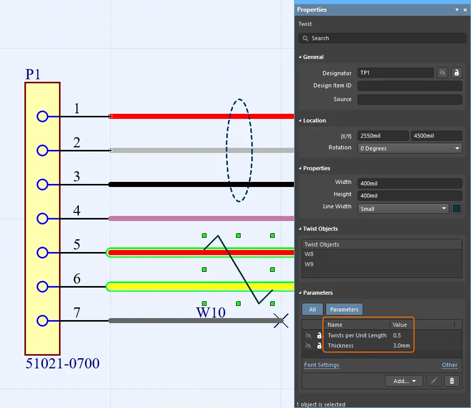 単位長さあたりのねじれ数と厚さは、ECADハーネスのTwistオブジェクトのパラメータとして定義されています。
ねじれていないワイヤーの長さは以下のように計算されます:

ワイヤー長さ(ねじれていない)= 1回転の長さ x 回転数
ここで:
回転数 = 単位長さあたりのねじれ数 * ケーブル長さ
単位長さあたりのねじれ数 = ケーブルの単位長さあたりのねじれ数で、ECADのTwistオブジェクトのパラメータとして定義されています
1回転の長さ = sqrt((ねじれピッチ)^2 + (pi*厚さ)^2)
ねじれピッチ = 1 / 単位長さあたりのねじれ数厚さ = ツイストペアの外径で、ECADのTwistオブジェクトのパラメータとして定義されています
► ハーネス設計プロジェクトの同期についてもっと学ぶ(PTC CreoとSOLIDWORKSで利用可能)
CoDesigner 3.7.0によってサポートされるバージョン
- Altium Designer 24.0(またはそれ以上)にMCAD CoDesigner拡張機能バージョン3.7.0.2033
- CoDesigner 3.4(およびそれ以上)はAltium NEXUS Clientでは利用できません。CoDesigner 3.3.0が最新バージョンです。
- CoDesigner 3.xはAltium CircuitMakerでは利用できません。CoDesigner 2.10が最新バージョンです。
このアップデートは、以下のMCADプラットフォームとアドインバージョンでテストされています:
TRANSLATE:
| MCADバージョン |
MCADアドインバージョン |
| Autodesk Fusion 360® (注1) |
3.7.0.7 |
| Autodesk Inventor Professional® - バージョン 2022, 2023, 2024 |
3.7.0.6 |
| Dassault Systemes SOLIDWORKS® - バージョン 2020, 2021, 2022, 2023, 2024 |
3.7.0.9 |
| PTC Creo Parametric® - 7.X, 8.X, 9.X, 10.X |
3.7.0.12 |
| Siemens NX® - バージョン 1953 - 2312 (注2) |
3.7.0.22 |
注記:
- Altium CircuitMakerはAutodesk Fusion 360のみをサポートしています。
- Siemens NXは、エンタープライズソフトウェアサブスクリプションを持つデザイナーのみが利用可能です。Siemens NXの新しいバージョンでは、現在のバージョンと署名されたバージョンの差が大きすぎるという警告が表示されることがあります。Siemens NXはv.2312までテストされており、この警告は無視しても構いません。または、Siemens NXのCustomer DefaultsダイアログでShow Warning when Loadingオプションを無効にすることができます(画像を表示
![]() )。
)。
Autodesk Fusion 360用CoDesigner 3.7.0ホットフィックスのリリースノート
Autodesk Fusion 360用CoDesigner 3.7.0ホットフィックスのリリースノート
| MCAD-4629 |
Autodesk Fusion 360 v.2.0.18220(2024年1月29日リリース)で行われた変更のため、銅とシルクスクリーンのジオメトリが誤って配置されました。修正済み。 |
CoDesigner 3.7.0ホットフィックスのリリースノート
CoDesigner 3.7.0ホットフィックスのリリースノート
| MCAD-4610 |
ECAD側で、ハーネスプロジェクトをプルする際、CoDesignerがMCADから転送されたケーブルの長さを読み取ることができませんでした。修正済み。 |
CoDesigner 3.7.0のリリースノート
TRANSLATE:
CoDesigner 3.7.0 リリースノート
| MCAD-3772 |
Autodesk Fusion 360、CoDesignerは「壊れたモデル」のバウンディングボックスを構築できませんでした。修正済み。 |
| MCAD-3773 |
Autodesk Fusion 360、MCADからプッシュする際、CoDesignerはジオメトリに対する参照なしに配置されたマウントホールの位置を正しく読み取れず(これはECADからホールを転送する際に発生します)、ボードの全体的なサイズが変更されてしまいました。修正済み。 |
| MCAD-3868 |
CoDesignerは、プロジェクト(バリアントを含む)からECADからMCADへユーザー定義のパラメータを転送し、それらをPCB/ハーネス/マルチボードアセンブリのプロパティとして割り当てるようになりました。 |
| MCAD-4072 |
マルチボードプロジェクトを同期する際、CoDesignerはプロジェクト内の複数レベルの階層をサポートするようになりました(以前は1レベルの階層のみ対応していました)。 |
| MCAD-4185 |
ECAD Route Tool Pathエンティティがサポートされるようになりました。MCADでは、押し出しカットとして表現されます。MCADでそのエンティティが変更された場合、ECADにボードカットアウトとして転送されます。 |
| MCAD-4290 |
Siemens NX、CoDesignerはSiemens Teamcenter内のアイテムにカスタムプロパティを割り当て、それらのプロパティをECADプロジェクト/バリアントプロパティにマッピングすることをサポートするようになりました。 |
| MCAD-4347 |
CoDesignerは、ECADとMCADの間でカウンターシンク/カウンターボアホールを両方向に同期するようになりました。MCADで「3D Copper」オプションがONの場合、これらのホールのために銅の正確なジオメトリが構築されます(ただし、Autodesk Fusion 360では3D Copperの構築はまだサポートされていません)。 |
| MCAD-4375 |
MCADへのプル時、CoDesignerの「変更」テーブルはコンポーネントをデフォルト名でリストしており、名前のカスタマイズは無視されていました。修正済み。 |
| MCAD-4390 |
Siemens NXおよびTeamcenter、CoDesignerはTeamcenterのPart IdentifierをECADからMCADへのコンポーネントリンクのマッピングプロパティとして使用することをサポートするようになりました。 |
| MCAD-4416 |
ハーネスプロジェクト内では、CoDesignerはTwisted PairsをMCADでケーブルとして同期し、ECADで設定された「単位長さあたりのねじれ」および「ワイヤーの厚さ」プロパティを考慮してワイヤーの物理的な長さを計算します。 |
| MCAD-4440 |
CoDesignerの設定は、"."(ドット)以外のシステム小数点区切り文字もサポートするようになりました。 |
| MCAD-4461 |
1つのMCADキープアウトスケッチ内の複数の輪郭の検出が正しいエラーメッセージを表示していませんでした。修正済み。 |
| MCAD-4463 |
Autodesk Inventor 2023、ECADからのプル中にCoDesignerパネルが隠されていたため、プルの進行状況を確認することができませんでした。修正済み。 |
| MCAD-4473 |
CoDesignerは、一部のケースで「手動で作成された曲げ」の誤ったエラーが発生するため、MCADへのプッシュ時にリジッドフレックスの曲げを検証しなくなりました。 |
| MCAD-4481 |
Siemens NX、CoDesignerはスケッチに構築ジオメトリが含まれている場合、ボードアウトラインスケッチを誤って処理していました。修正済み。 |
| MCAD-4484 |
PTC Creo、ワイヤーハーネスを構築する際、CoDesignerは手動で通すのと同じ方法でワイヤーを接続ポイントを通過させるようになりました。以前は、ワイヤーが互いに交差しており、手動で再ルーティングする必要がありました。 |
| MCAD-4535 |
Siemens NXおよびTeamcenter、NXでのMCAD CCIDマッピングのカテゴリサポートを追加しました。 |
| MCAD-4543 |
Siemens NXバージョン2312がサポートされるようになりました。 |
| MCAD-4545 |
Siemens NX、デバイスアセンブリのコンテキストからの変更のプルは、多くのケースで正しく動作しなかったため、一時的に無効化されました。問題は次のアップデートで修正される予定です。 |
TRANSLATE:
CoDesigner 3.6.0の新機能
リリース日: 2023年11月2日 – バージョン3.6.0
TRANSLATE:
機能ハイライト
SOLIDWORKSでのマルチボードアセンブリのサポートに基づき、MCAD CoDesignerの3.6アップデートでは、ハーネスの同期がサポートされ、マルチボードアセンブリの一部として含めることができます。SOLIDWORKS 2024のサポートも追加されました。このCoDesignerのリリースでは、マルチボードアセンブリの変更をプレビューするサポートも追加され、サポートされているすべてのMCADは、リジッドフレックスボードエッジ検出のサポートが向上しています。
SOLIDWORKSでのハーネス設計プロジェクトの同期(ベータ版)
配線ハーネスは多くのアセンブリで一般的に見られ、デバイス内のさまざまなPCBを電気的に接続するだけでなく、ユーザーが操作するさまざまなボタン、ディスプレイ、コントロールの配線も行います。SOLIDWORKSでのマルチボードアセンブリのサポートに基づき、ハーネス同期はECADからMCADへのハーネス要素(コネクタ、ワイヤ、スプライス、接続性(from-toデータ)およびハーネストポロジー)の転送をサポートし、さらにMCADからECADへのワイヤ、ケーブル、ハーネスセグメントの物理的長さの転送をサポートします。
ハーネスの3Dモデルも、機械的エンクロージャ部品とともに、マルチボードアセンブリ同期中にECADに送信することができます。
► Altium MCAD CoDesignerでのハーネス設計プロジェクトの同期についてもっと学ぶ。
 CoDesignerを使用して、SOLIDWORKSとAltium Designerでハーネスを共同設計できます。
- ハーネス同期には、Altium Designer ProまたはAltium Designer Enterpriseのソフトウェアサブスクリプションが必要です。
- この機能は現在、MCADハーネスFocused Betaグループのメンバーのみが利用可能です。もっと学ぶ...
SOLIDWORKS 2024のサポート
Altium MCAD CoDesignerの3.6アップデートでSOLIDWORKS 2024のサポートが追加されました。
 Altium MCAD CoDesignerは現在SOLIDWORKS 2024をサポートしています(Dassault Systemesの画像提供)
マルチボードアセンブリの変更プレビュー
マルチボードプロジェクトでは、CoDesignerはECADとMCADの両方で同期変更のプレビューを表示します。
 適用する前に、マルチボードアセンブリの各変更の影響を確認します。
ネストされたプロジェクトのサポート
CoDesignerは現在、ネストされたマルチボードプロジェクトの変更を同期します。以前は、ネストされたマルチボードプロジェクトごとに個別に同期する必要がありました。
リジッドフレックスボードエッジ検出の改善
ECADからのプッシュ時にボードの輪郭を検出するアルゴリズムが改善されました。例えば、接線曲線のような非常に鋭角を含むボード領域は、もはやエラーとは見なされません。これらはプッシュ時に警告としてフラグが立てられ、MCADへのプル時に受け入れることができます。
 鋭角を含むリジッドフレックスボード領域のプッシュサポートが改善されました。
SOLIDWORKSでのリジッドフレックス曲げのサポートの改善
以前は、SOLIDWORKS用のCoDesignerは、フレックス領域内に多数の曲げがある場合、正しく曲げを処理しませんでした。この制限は解除されました。
TRANSLATE:
対応バージョン
- Altium Designer 23.9.1(またはそれ以上)にMCAD CoDesigner拡張機能バージョン3.6.0.1976
- CoDesigner 3.6はAltium NEXUSクライアントには利用できません。CoDesigner 3.3.0が最新バージョンです。
- CoDesigner 3.xはAltium CircuitMakerには利用できません。CoDesigner 2.10が最新バージョンです。
このアップデートは以下のMCADプラットフォームとアドインバージョンでテストされています:
| MCADバージョン |
MCADアドインバージョン |
| Autodesk Fusion 360® (注1) |
3.6.0.16 |
| Autodesk Inventor Professional® - バージョン 2022, 2023, 2024 |
3.6.0.15 |
| Dassault Systemes SOLIDWORKS® - バージョン 2021, 2022, 2023, 2024 |
3.6.0.34 |
| PTC Creo Parametric® - 7.X, 8.X, 9.X, 10.X |
3.6.0.26 |
| Siemens NX® - バージョン 1953 - 2306 (注2) |
3.6.0.19 |
注記:
- Altium CircuitMakerはAutodesk Fusion 360のみをサポートしています。
- Siemens NXはエンタープライズソフトウェアサブスクリプションを持つデザイナーのみが利用可能です。Siemens NXの新しいバージョンでは、現在のバージョンと署名されたバージョンの差が大きすぎるという警告が表示される場合があります。Siemens NXはv.2306までテストされており、この警告は無視しても構いません。または、Siemens NXのCustomer DefaultsダイアログでShow Warning when Loadingオプションを無効にすることができます(画像を表示
![]() )。
)。
TRANSLATE:
CoDesigner 3.6.0 リリースノート
| MCAD-4104 |
マルチボードプロジェクトでは、CoDesignerはECADとMCADの両方で同期変更のプレビューを表示するようになりました。 |
| MCAD-4105 |
マルチボードプロジェクトでは、CoDesignerはネストされたプロジェクトの変更を同期するようになりました。以前は一度に一つのレベルでのみ機能していました。 |
| MCAD-4109 |
SOLIDWORKS 2024がサポートされるようになりました。 |
| MCAD-4114 |
マルチボードプロジェクトでは、子プロジェクトで既にエンクロージャとして宣言されているエンクロージャの部分をCoDesignerが同期できない問題がありました。修正されました。 |
| MCAD-4117 |
マルチボードプロジェクトでは、ECADへの同期時に「MoveBoard」操作が考慮されておらず、これによりECADのマルチボードアセンブリ内でPCBが移動してしまう問題がありました。修正されました。 |
| MCAD-4123 |
Siemens NXでは、MCADからプッシュする際に、他のMCADからプッシュする際と同様に、サポートされていない機能が使用されている場合にユーザーに警告するようにCoDesignerが機能するようになりました。 |
| MCAD-4149 |
MCADの「プル用プロジェクトを選択」ダイアログでは、サーバー側のフォルダがリストの上部に表示されるようになりました。 |
| MCAD-4154 |
CoDesignerは、Altium DesignerとSOLIDWORKS間でハーネスプロジェクトを同期することをサポートするようになりました。CoDesignerは、ECADのハーネスレイアウト図面ドキュメントからMCADに次の情報を送信します:コネクタ、スプライス、接続性(「from-to」データ)、ハーネストポロジー(接続点とそれらの点を通るワイヤーとケーブルのセット)。MCADからは、CoDesignerが3Dルーティングの結果をハーネスレイアウト図面に戻します:ワイヤー、ケーブル、ハーネスセグメントの物理的長さ。 |
| MCAD-4179 |
PTC Creoでは、CoDesignerはケーブルの物理的ルーティングを構築するようになりました(以前は、ケーブル内のワイヤーに対してのみ可能でした)。 |
| MCAD-4256 |
SOLIDWORKSでは、CoDesignerはリジッドフレックスボードのフレックス領域にある比較的大量の曲げを処理できませんでした。修正されました。 |
| MCAD-4257 |
SOLIDWORKSでは、銅、シルクスクリーン、はんだマスクを表すデカール画像が、リジッドフレックスボードの対応するリジッド領域を表す部品に埋め込まれるようになりました。 |
| MCAD-4335 |
ECADからプッシュする際のボードの輪郭に関するエラーを検出するアルゴリズムが改善されました。非常に鋭角な角度(通常は接線のケース)はもはやプッシュの障害とは見なされず、警告としてフラグが立てられるようになりました。 |
| MCAD-4358 |
SOLIDWORKSでは、SOLIDWORKSの設定で「新しい部品にスケッチを作成」オプションが有効になっている場合、CoDesignerはMCADでPCBを構築できませんでした。修正されました。 |
CoDesigner 3.5.0の新機能
リリース日: 2023年8月17日 – バージョン 3.5.0 – ホットフィックス(Altium Designer CoD拡張機能に変更なし)
リリース日: 2023年7月27日 – バージョン 3.5.0
TRANSLATE:
機能のハイライト
Altium MCAD CoDesignerの3.5リリースでは、PTC Creoにマルチボードアセンブリのサポートが追加され、新機能として、ECADとMCAD(初期ベータリリースではCreoのみ)間でハーネス設計を同期する機能が導入されました。ハーネス同期は、ECADマルチボードアセンブリで定義されたハーネスをPTC Creoにプッシュし、機械エンジニアがエンクロージャーを通るケーブルのルーティングとプリント回路基板への接続を定義できるようにサポートします。その後、ハーネス定義をMCADからECADにマルチボードアセンブリの一部としてプッシュすることができます。
ハーネス設計プロジェクトの同期(ベータ)
多くのアセンブリには、1つ以上の配線ハーネスが含まれています。ハーネスは、デバイス内のさまざまなPCBを電気的に接続するために使用されるほか、ユーザーが操作するさまざまなボタン、ディスプレイ、コントロールの配線にも使用されます。PTC Creoでのマルチボードアセンブリのサポートに基づいて(以下の機能ハイライトを参照)、ハーネス同期はECADからMCADへのハーネス要素(コネクタ、ワイヤ、スプライス、接続性(from-toデータ)およびハーネストポロジー)の転送と、物理的なワイヤ、ケーブル、ハーネスセグメントの長さのMCADからECADへの転送をサポートします。
ハーネスの3Dモデルも、マルチボードアセンブリ同期中に機械エンクロージャーパーツと共にECADに送信することができます。
► Altium MCAD CoDesignerでのハーネス設計プロジェクトの同期についてもっと学ぶ。
 CoDesignerのハーネスサポートを使用して、ハーネス設計に協力的に取り組む。
- ハーネス同期には、Altium Designer ProまたはAltium Designer Enterpriseのソフトウェアサブスクリプションが必要です。
- この機能は現在、MCADハーネスFocused Betaグループのメンバーのみが利用可能です。
PTC Creoでのマルチボードアセンブリのサポート
多くの電子デバイスは、複数の回路基板のアセンブリとして構築され、機械エンクロージャー内に巧みに形作られ配置され、美的で実用的な製品を提供します。Altiumの電子設計(ECAD)ソフトウェアはこれをサポートしており、複数のPCBをまとめてPCBのアセンブリを作成できます。これはマルチボードアセンブリと呼ばれ、製品を構成するエンクロージャーやその他の機械要素も含むことができます。
 Altiumのマルチボードアセンブリエディタで開かれたマルチボードアセンブリ。
PCBをエンクロージャーに組み立てるプロセスは、MCADで最も適切に実行されます。しかし、PCBはECADで設計され、ECADエンジニアはコンポーネント間、コンポーネントとエンクロージャー間のクリアランスのチェック、およびインジケーターやディスプレイ、ボタン、コネクターなどの人間インターフェース要素へのアクセスのチェックなど、電気機械的なチェックを実行する必要があるかもしれません。MCADとECADの領域間で組み立てられたデバイス全体を同期できることには、機械設計チームと電子設計チームの両方が組み立てられたデバイスの現状を迅速に確認できる多くの利点があります。
Altium CoDesigner 3.5では、マルチボードアセンブリのサポートがベータ版から正式版に移行しました。SOLIDWORKSからのマルチボードアセンブリ同期をサポートするだけでなく、PTC Creoからのマルチボードアセンブリ同期もサポートされるようになりました。
► Altium MCAD CoDesignerでのマルチボードアセンブリの同期についてもっと学ぶ。

マルチボード同期には、Altium Designer ProまたはAltium Designer Enterpriseのソフトウェアサブスクリプションが必要です。
MCADへのプル時のワークスペースフォルダのサポート
Altiumワークスペースフォルダは、MCADに新しいPCBをプルするときに<ワークスペース>からプロジェクトを選択ダイアログに表示されるようになりました。ダイアログは、すべてのフォルダーのすべてのプロジェクトを表示するか、フォルダー内のプロジェクトを表示することができます。ダイアログの上部にある ボタンをクリックして表示モードを切り替え、標準のWindowsテクニックを使用してフォルダーをドリルダウンします。
 プロジェクトストレージフォルダは、MCADからプルをクリックするときの<ワークスペース>からプロジェクトを選択ダイアログでサポートされています。
PTC Creo 10のサポート
PTC Creoバージョン10のサポートが、Altium MCAD CoDesignerの3.5アップデートで追加されました。
 Altium MCAD CoDesignerは現在PTC Creo V10をサポートしています(PTC提供の画像)
Autodesk Inventor 2024のサポート
Autodesk Inventor 2024のサポートが、Altium MCAD CoDesignerの3.5アップデートで追加されました。

TRANSLATE:
対応バージョン
- Altium Designer 23.5.1(またはそれ以上)にMCAD CoDesigner拡張機能バージョン3.5.0.1900
- CoDesigner 3.5はAltium NEXUS Clientには利用できません。CoDesigner 3.3.0が最新バージョンです。
- CoDesigner 3.xはAltium CircuitMakerには利用できません。CoDesigner 2.10が最新バージョンです。
このアップデートは以下のMCADプラットフォームとアドインバージョンでテストされています:
| MCADバージョン |
MCADアドインバージョン |
| Autodesk Fusion 360® (注1) |
3.5.0.17 |
| Autodesk Inventor Professional® - バージョン 2022, 2023, 2024 |
3.5.0.14 |
| Dassault Systemes SOLIDWORKS® - バージョン 2020, 2021, 2022, 2023 |
3.5.0.24 |
| PTC Creo Parametric® - 7.X, 8.X, 9.X, 10.X |
3.5.0.21 |
| Siemens NX® - バージョン 1953以降 (注2) |
3.5.0.12 |
注記:
- Altium CircuitMakerはAutodesk Fusion 360のみをサポートしています。
- Siemens NXはエンタープライズソフトウェアサブスクリプションを持つデザイナーのみが利用可能です。
CoDesigner 3.5.0ホットフィックスのリリースノート
| MCAD-4221 |
プッシュとプルの数が多い場合、MCADのCoDesignerは最新のプッシュからではなく、ECADのプッシュ日時とコメントを表示していました。修正されました。 |
TRANSLATE:
CoDesigner 3.5.0 リリースノート
| MCAD-2210 |
Altium WorkspaceフォルダがMCADの「<Workspace>からプロジェクトを選択」ダイアログに表示されるようになりました。 |
| MCAD-3892 |
CoDesignerは、SOLIDWORKSで「完全に定義されたスケッチを使用する」設定がONになっているかどうかをチェックし、PCBが構築された後にその状態を復元します(CoDesignerはまだ完全に定義されたスケッチを作成できませんが、以前はその設定が尊重されていませんでした)。 |
| MCAD-3905 |
CoDesignerは、Altium DesignerとPTC Creo間でハーネスプロジェクトの同期をサポートするようになりました。CoDesignerは、ECADハーネスレイアウト図面ドキュメントからMCADに次の情報を送信します:コネクタ、スプライス、接続性(「from-to」データ)、ハーネストポロジー(接続点と、それらの点を通過するワイヤーとケーブルのセット)。MCADからは、CoDesignerは3Dルーティングの結果をハーネスレイアウト図面に戻します:ワイヤー、ケーブル、ハーネスセグメントの物理的長さ。注1:同期を開始するには、ハーネスレイアウト図面には、配線図から転送されたコネクタが少なくとも含まれている必要があります。注2:ネイティブのECADからMCADへのコンポーネントリンケージを使用して、ECADから転送されたコネクタの代わりにMCADストレージからコネクタモデルを配置することができます。注3:CoDesignerは、MCADから同期を戻した後、ECADのレイアウト図面にハーネストポロジーを構築しませんので、戻す前にそのドキュメントでハーネストポロジーを指定する必要があります。注4:ハーネスの3Dモデルは、マルチボードアセンブリ同期中に、機械的エンクロージャーパーツとともにECADに送信することができます。 |
| MCAD-4032 |
CoDesignerは、PTC Creoでマルチボードアセンブリの同期をサポートするようになりました。注1:以前は、この機能はSOLIDWORKSでのみ利用可能でした。注2:この機能は、PTC CreoとSOLIDWORKSの両方でベータモードです。 |
| MCAD-4039 |
CoDesignerは、3Dフィレット/面取りなどのサポートされていない機能の使用について、機械エンジニアに警告していませんでした。修正されました。 |
| MCAD-4054 |
Workspaceにまだ含まれていない機械エンジニアとPCBプロジェクトを共有するフローが変更されました:現在、すべてのワークスペース管理者に「追加して共有」のリクエストが自動的に送信されます。承認されると、その外部の機械エンジニアは自動的にワークスペースに追加され、プロジェクトが彼/彼女と共有されます(以前は、これらのステップを手動で行う必要がありました)。 |
| MCAD-4056 |
SOLIDWORKS 2023では、場合によっては「壊れたコンポーネントモデル」がすべてのモデルの一括配置をブロックしていました。修正されました(CoDesignerは現在、そのようなケースを検出し、モデルを個別に配置します)。 |
| MCAD-4058 |
PTC Creo 10がサポートされるようになりました。 |
| MCAD-4059 |
Autodesk Inventor 2024がサポートされるようになりました。 |
| MCAD-4060 |
Autodesk Fusion 360では、場合によってはボードアウトラインスケッチのアークの端が隣接するスケッチセグメントの端と関連付けられておらず、スケッチの編集が困難になっていました。修正されました。 |
| MCAD-4076 |
SOLIDWORKSでは、CoDesignerの設定で3D銅をONにした後、変更をプルする前にデカールが隠されていました。修正され、次のプルが行われるまでデカールは表示されたままです。 |
| MCAD-4083 |
CoDesignerは、SOLIDWORKSでリジッドフレックスPCBを扱う際に「スナッピングを有効にする」設定をリセットし、それを復元しませんでした。修正されました。 |
| MCAD-4084 |
CoDesignerは、機械エンジニアに、CoDesignerの設定で設定された高さ制限に従って無視(フィルタリング)されるコンポーネントの数を通知するようになりました(コンポーネントの表示/非表示に関する混乱を避けるため)。 |
| MCAD-4142 |
Siemens NXでは、スケッチに寸法を作成した後にボードスケッチを編集すると、「サポートされていないカーブタイプ'SketchVirtualPoint'」というエラーが表示されていました。修正されました。 |
| MCAD-4147 |
PTC Creoでは、コンポーネントのサイズによるフィルタリングがONになっていて、フィルタリングされたコンポーネントの数とそのプロパティが多い場合、PCBの2回目のプルが失敗していました。修正されました。 |
TRANSLATE:
CoDesigner 3.4.0の新機能
リリース日: 2023年5月29日 – バージョン 3.4.0.1859 – GovCloud用ホットフィックス
リリース日: 2023年4月10日 – バージョン 3.4.0.1792 – ホットフィックス
リリース日: 2023年3月23日 – バージョン 3.4.0
TRANSLATE:
対応バージョン
- Altium Designer 22.11.1(またはそれ以上)とMCAD CoDesigner拡張機能バージョン3.4.0.1859
- CoDesigner 3.4はAltium NEXUSクライアントには利用できません。CoDesigner 3.3.0が最新バージョンです。
- CoDesigner 3.xはAltium CircuitMakerには利用できません。CoDesigner 2.10が最新バージョンです。
| MCADバージョン |
MCADアドインバージョン |
| Autodesk Inventor Professional® - バージョン2022、2023 |
3.4.0.8 |
| Autodesk Fusion 360® (注1) |
3.4.0.9 |
| Dassault Systemes SOLIDWORKS® - バージョン2020、2021、2022、2023 |
3.4.0.12 |
| PTC Creo Parametric® - 7.X、8.X、9.X |
3.4.0.7 |
| Siemens NX® - バージョン1953以降 (注2) |
3.4.0.13 |
注記:
- Altium CircuitMakerはAutodesk Fusion 360のみをサポートしています。
- Siemens NXはエンタープライズソフトウェアサブスクリプションを持つデザイナーのみが利用可能です。
CoDesigner 3.4.0.1859のリリースノート(GovCloudサポートのためのホットフィックス)
| MCAD-4024 |
Altium 365 GovCloud(https://www.altium.com/trust/govcloud)のサポートが追加されました。 |
CoDesigner 3.4.0.1792のリリースノート
| MCAD-3951 |
ECAD拡張機能の変更リストで、変更の数が多い場合にスクロールと列のリサイズが機能しなくなっていました。修正されました。 |
TRANSLATE:
[折りたたみ 折りたたまれたクラス="" タイトル="CoDesigner 3.4.0のリリースノート" id="release_notes_for_codesigner_3-4-0"]
| MCAD-2958 |
MCADに変更を取り込む際、ECADでボードのアウトラインに変更があった場合、CoDesignerは変更テーブルで対応する変更をハイライトし、その変更に対応するツールチップを表示します。これにより、機械エンジニアが作成した寸法や制約を(次の同期ステップで)失うことを防ぐか、または、失われた寸法や制約を機械エンジニアが復元するのに役立ちます。 |
| MCAD-3248 |
Siemens NXでは、MCADでPCBコンポーネントを配置し、ECADでそれらを認識する機能がサポートされるようになりました。 |
| MCAD-3249 |
Siemens NXでは、Teamcenterから自動的にPCBコンポーネントモデルを配置する機能がサポートされるようになりました。注:ECADコンポーネント/フットプリントプロパティでは、MCADモデル参照にTeamcenterパスを含める必要があります。例::root_TC_folder:subfolder1:subfolder12:model_name |
| MCAD-3250 |
Siemens NXでは、「Advanced Copper Geometry」機能(銅層、銅バレル、ビア、はんだマスクの正確な3Dモデルを作成する)がサポートされるようになりました。 |
| MCAD-3319 |
MCADデータ管理システムからコンポーネントモデルを自動的に配置する場合、CoDesignerは、既存のカスタムコンポーネントパラメータを使用することに加えて、ECADカスタムフットプリントパラメータからMCADモデルの名前を取得することをサポートするようになりました。この機能は、コンポーネントとフットプリントの多対多の関係をよりよくサポートします。CoDesignerが現在従うロジックは次のとおりです:ECADからプッシュする際、CoDesignerはAltium WorkspaceでUse models from data management system on MCAD side when creating PCB assemblyオプションが有効になっているかどうかを確認し、有効であれば、Workspaceで指定されたパラメータがフットプリントパラメータとして存在し、空でないかどうかを確認し、パラメータとその値をMCADに送信し、その後、MCADにプルする際に、フットプリントパラメータの値に従ってMCADストレージからMCADモデルを取得します。フットプリントパラメータが割り当てられていない場合、または空の場合、CoDesignerは代わりにコンポーネントパラメータからMCADモデル名を取得します(空でない場合)。Altium Designerでフットプリントパラメータを使用するには、現在ベータ版であるため、Altium DesignerでAdvanced Option PCB.FootprintParametersが有効になっていることを確認してください。 |
| MCAD-3589 |
SOLIDWORKSでは、リジッドフレックス2.0モードで設計されたPCBを更新する際、CoDesignerはECADで変更された領域のジオメトリのみを再描画するようになりました。これにより、設計者は他の領域に対して作成されたMCADの寸法と制約を維持することができます。 |
| MCAD-3753 |
Autodesk Fusion 360では、ボードのアウトラインを構築する際、CoDesignerは連続するスケッチセグメントを互いに制約するようになり、機械エンジニアがスケッチを変更するのが容易になりました。 |
| MCAD-3778 |
機械エンクロージャの個々のパーツを送信するアルゴリズムが改善されました。以前は、MCADで複数のパーツを同時に保存すると(例えば、交換フォーマットからインポートする場合)、ECADにプルする際にエラーが発生することがありました。修正されました。 |
| MCAD-3783 |
Autodesk Fusion 360では、プッシュ時にCoDesignerがボードスケッチが外部ジオメトリを参照している場合を正しく検出し、「無効なフィーチャープロファイル:ボード」というエラーメッセージを表示するようになりました。このようなスケッチはECADにプッシュすることはできません。 |
| MCAD-3831 |
Siemens NXでは、NX v.2xxxのサポートが追加されました。 |
| MCAD-3857 |
Autodesk Fusion 360では、CoDesignerツールを使用してキープアウトとカットアウトを作成する機能が、デバイスアセンブリコンテキストが誤って検出されたために機能しなくなっていました。修正されました。 |
| MCAD-3930 |
SOLIDWORKSで変更をプルする際、CoDesignerは「コンポーネントプロパティの同期」の変更をデフォルトでチェックされていない状態に保ちます。これにより、ユーザーはSOLIDWORKS PDMから手動でコンポーネントをチェックアウトする必要がなくなります。注:ECADとMCADストレージのプロパティが異なる理由を確認することをお勧めします。 |
[/折りたたみ]
TRANSLATE:
CoDesigner 3.3.0の新機能
リリース日: 2022年12月21日 – バージョン 3.3.0
このリリースには新機能は含まれていません。
対応バージョン
- Altium Designer 22.6(またはそれ以上)にMCAD CoDesigner拡張機能バージョン 3.3.0.1753
- Altium NEXUS Client 5.6から5.8まで、MCAD CoDesigner拡張機能バージョン 3.3.0.497
- CoDesigner 3.xはAltium CircuitMakerには利用できません。CoDesigner 2.10が最新バージョンです。
このアップデートは以下のMCADプラットフォームとアドインバージョンでテストされています:
| MCADバージョン |
MCADアドインバージョン |
| Autodesk Inventor Professional® - バージョン 2022, 2023 |
3.3.0.6 |
| Autodesk Fusion 360® (注1) |
3.3.0.6 |
| Dassault Systemes SOLIDWORKS® - バージョン 2020, 2021, 2022, 2023 |
3.3.0.9 |
| PTC Creo Parametric® - 7.X, 8.X, 9.X |
3.3.0.6 |
| Siemens NX® - バージョン 1953以降 (注2) |
3.3.0.8 |
注記:
- Altium CircuitMakerはAutodesk Fusion 360のみをサポートしています。
- Siemens NXはエンタープライズソフトウェアサブスクリプションを持つデザイナーのみが利用可能です。
TRANSLATE:
[リリースノート id="release_notes_for_codesigner_3-3-0"]
| MCAD-3587 |
SOLIDWORKSおよびPTC Creoでは、CoDesignerはリジッドフレックス基板のリジッドセグメントにKeepoutsとRoomsを定義するサポートが追加されました。 |
| MCAD-3650 |
オンプレミスサーバーでのAltiumのライセンスのチェック方法が変更されました。以前は、"Pro"機能がオンプレミスサーバーでデフォルトで利用可能でした。現在、CoDesignerは"Pro"機能を個別にチェックします。最近導入された"Pro"機能 - マルチボード同期とKeepout/Room同期 - を使用するには、"Altium Enterprise Server & CAL"ライセンスを更新する必要があります。 |
| MCAD-3666 |
Altiumのライセンスポリシーに沿って、MCADでのKeepoutsとRoomsの作成は、現在"PRO"および"Enterprise"サブスクリプションのみで可能です。注:以前に"Standard"サブスクリプションでMCADで作成されたKeepoutsとRoomsは影響を受けませんが、これからの変更はECADには転送されなくなります。 |
| MCAD-3745 |
SOLIDWORKSでは、リジッドフレックス2.0基板のボードセグメントの結合方法が改善され、潜在的な微細なアライメント問題を避けるために追加の角度メイトが適用されました。 |
| MCAD-3746 |
Siemens NXでは、CoDesignerはSiemens TeamcenterでPCBエンティティを格納するためのカスタムアイテムタイプの設定をサポートするようになりました。 |
| MCAD-3812 |
CoDesignerは、Firebird DBMSが使用されているオンプレミスサーバーを介してマルチボードプロジェクトを同期できませんでした。 |
[/リリースノート]
CoDesigner 3.2.0の新機能
リリース日: 2022年11月17日 – バージョン 3.2.0
TRANSLATE:
対応バージョン
- Altium Designer 22.6(またはそれ以上)でMCAD CoDesigner拡張機能バージョン3.2.0.1730
- Altium NEXUS Client 5.6から5.8まで、MCAD CoDesigner拡張機能バージョン3.2.0.490
- CoDesigner 3.xはAltium CircuitMakerには利用できません。CoDesigner 2.10が最新バージョンです。
このアップデートは以下のMCADプラットフォームおよびアドインバージョンでテストされています:
| MCADバージョン |
MCADアドインバージョン |
| Autodesk Inventor Professional® - バージョン2022, 2023 |
3.2.0.8 |
| Autodesk Fusion 360® (注1) |
3.2.0.7 |
| Dassault Systemes SOLIDWORKS® - バージョン2020, 2021, 2022, 2023 |
3.2.0.11 |
| PTC Creo Parametric® - 7.X, 8.X, 9.X |
3.2.0.8 |
| Siemens NX® - バージョン1953以降 (注2) |
3.2.0.8 |
注釈:
- Altium CircuitMakerはAutodesk Fusion 360のみをサポートしています。
- Siemens NXはエンタープライズソフトウェアサブスクリプションを持つデザイナーのみが利用可能です。
TRANSLATE:
[折りたたみ 折りたたまれたクラス="" タイトル="リリースノート" id="release_notes_for_codesigner_3-2-0"]
| MCAD-2932 |
MCADでは、CoDesignerはECADからMCADへの同期中に提案されたコンポーネントプロパティの変更に関する詳細情報を表示するようになりました(以前は、これらの変更は変更リストの単一のレコードで表されていました)。これにより、MCADまたはPDMによる前回の同期で自動的に変更されたために、ECADとMCADのライブラリが同期していない場合に、機械エンジニアが状況を調査するのに役立ちます。 |
| MCAD-3404 |
PTC Creoでは、3D銅を構築するアルゴリズムが改善されました:小さな銅の要素を繰り返し構築する際の問題が修正され、全体的なパフォーマンスが向上しました。 |
| MCAD-3498 |
PTC Creo、Creoバージョン9に対応しました。 |
| MCAD-3500 |
CoDesignerは、デカールの画像が大きなPCB(デカールのサイズが32768ピクセルを超える場合)のために切り取られていました。修正しました。 |
| MCAD-3510 |
SOLIDWORKSでは、1つ以上の領域をカバーするカットアウトを構築するために、CoDesignerは現在SOLIDWORKS由来のスケッチを使用します。 |
| MCAD-3590 |
PTC Creoでは、ECADでボードのアウトラインに変更が加えられた後、CoDesignerはリジッドフレックスボードの変更された領域のみを再構築します(以前は、ボード全体が再構築されていました)。 |
| MCAD-3599 |
CoDesignerには、ユーザーに関連付けられたワークスペースがない場合、MCADで「デモモード」が含まれるようになりました。デモモードでは、機械エンジニアは次のことができます:a) MCADのネイティブ形式でデモPCBのモデルを構築し、モデルの構造を確認し、エンクロージャとの関連付け/制約方法を確認する、b) 変更の制御方法を確認する(CoDesignerはデモPCBへのECADの変更をシミュレートします)、c) 銅の正確な3Dジオメトリを構築する(3D銅の構築は、Autodesk Fusion 360およびSiemens NXではまだサポートされていません)、d) ボードの形状の変更、コンポーネントの配置、取り付け穴の作成、キープアウト/ルームの作成を含む機械的PCB定義を確認する。 |
| MCAD-3647 |
SOLIDWORKSおよびPTC Creoでは、リジッドフレックスPCBを折りたたむ/展開するためのボタンがCoDesignerリボンツールバーに追加されました。以前は、機械エンジニアはMCADモデルツリーで曲げ機能を手動で抑制/解除することによってリジッドフレックスPCBを折りたたむ/展開する必要がありました。 |
| MCAD-3686 |
MCADでは、Altium CoDesignerパネルの上部にある「Webで開く」ボタンをクリックすることで、Altium Workspace Web UIでPCB/マルチボードプロジェクトを開くことができるようになりました。 |
| MCAD-3718 |
SOLIDWORKSでは、CoDesignerの設定で「3D銅」オプションがONになっている場合、PCBが最初に引き出されたときにスナップ設定がデフォルト状態にリセットされていました。修正しました。 |
| MCAD-3728 |
PCBプロジェクト名は、SOLIDWORKSでリジッドフレックスボードの異なる領域を表す部品およびサブアセンブリの名前に含まれるようになり、PDMで名前の一意性の制御がONになっている場合の作業が簡単になりました。 |
[/折りたたみ]
CoDesigner 3.1.0の新機能
リリース日: 2022年10月4日 – バージョン 3.1.0
TRANSLATE:
対応バージョン
- Altium Designer 22.6(またはそれ以上)でMCAD CoDesigner拡張機能バージョン3.1.0.1709
- Altium NEXUS Client 5.6から5.8まで、MCAD CoDesigner拡張機能バージョン3.1.0.487
- CoDesigner 3.xはAltium CircuitMakerには対応していません。CoDesigner 2.10が最新の対応バージョンです。
このアップデートは、以下のMCADプラットフォームおよびアドインバージョンでテストされています:
| MCADバージョン |
MCADアドインバージョン |
| Autodesk Inventor Professional® - バージョン2022、2023 |
3.1.0.11 |
| Autodesk Fusion 360® (注1) |
3.1.0.9 |
| Dassault Systemes SOLIDWORKS® - バージョン2020、2021、2022、2023 |
3.1.0.35 (注3) |
| PTC Creo Parametric® - 7.X、8.X |
3.1.0.28 |
| Siemens NX® - バージョン1953以降 (注2) |
3.1.0.9 |
注釈:
- Altium CircuitMakerはAutodesk Fusion 360のみをサポートしています。
- Siemens NXは、エンタープライズソフトウェアサブスクリプションを持つデザイナーのみが利用可能です。
- これは10月4日のリリース時には3.1.0.34でした。Symantec Antivirusが以前のバージョンをウイルスとして検出したため、おそらく誤って、この後のバージョンが提供されました。この後のバージョンでは機能に変更はありません。
TRANSLATE:
[折りたたみ 折りたたまれたクラス="" タイトル="リリースノート" id="release_notes_for_codesigner_3-1-0"]
| MCAD-2438 |
CoDesignerは、異なるレイヤースタックで同じ名前が定義されている2つ以上のレイヤーがある場合、リジッドフレックスPCBをECADからプッシュすることができませんでした。修正済み。 |
| MCAD-3234 |
MCADでカスタムサーバーに接続されている場合、そのサーバーの名前がプラグインに表示されるようになりました(以前は「カスタムサーバー」と表示されていました)。 |
| MCAD-3242 |
CoDesignerは、過去の年に変更が行われた場合、混乱を避けるためにその変更の年を履歴に表示するようになりました。 |
| MCAD-3466 |
CoDesignerは、Advanced Rigid-Flex(RF2)モードで設計されたPCBをSOLIDWORKSおよびPTC Creoと同期するようになりました。
注1:SOLIDWORKSでのRF2モードのPCBアセンブリの構造は、RF1モードのアセンブリの構造と異なるため、ECADでRF1からRF2にモードが切り替えられた場合、SOLIDWORKSでボードを新たにプルすることをお勧めします。
注2:トップ/ボトムの銅、シルクスクリーン、はんだマスクを表すデカールは、SOLIDWORKSのRF2モードでリジッド領域に適用されるようになりました。
注3:MCADでの新しい領域や曲げの作成はまだサポートされておらず、フレックス領域にデカールを適用することもできません。 |
| MCAD-3528 |
Autodesk Inventor 2023では、プロジェクトを選択するダイアログが背景に移動し、これ以上の作業ができなくなることがありました。修正済み。 |
| MCAD-3548 |
SOLIDWORKS 2023がサポートされるようになりました。 |
| MCAD-3655 |
Altiumサーバーのセキュリティポリシーに加えられた変更により、通常のECADユーザー(管理者以外)は外部の機械エンジニアをワークスペースに招待することができなくなりました。この状況では、ECAD CoDesigner拡張機能でプッシュ中に共有オプションを有効にする動作が変更されました:CoDesignerは、管理者以外のECADユーザーに対して、外部の機械エンジニアをワークスペースに招待するためにはワークスペース管理者が必要であることを報告するようになりました。 |
| MCAD-3658 |
Autodesk InventorのデフォルトリボンにCoDesignerボタンが追加されました。これを使用してCoDesignerパネルを開き、Autodesk Inventor 2023でファイルが開かれていない場合にパネルにアクセスできなかった問題を解決します。 |
[/折りたたみ]
CoDesigner 3.0.0の新機能
リリース日: 2022年7月18日 – バージョン 3.0.0
TRANSLATE:
[折りたたみ クラス="" タイトル="対応バージョン" id="versions_supported_by_codesigner_3-0-0"]
- Altium Designer 22.6(またはそれ以上)でMCAD CoDesigner拡張機能バージョン3.0.0.1610
- Altium NEXUS Client 5.6から5.8まで、MCAD CoDesigner拡張機能バージョン3.0.0.474
- CoDesigner 3.0はAltium CircuitMakerには利用できません。CoDesigner 2.10が最新バージョンです。
このアップデートは以下のMCADプラットフォームおよびアドインバージョンでテストされています:
| MCADバージョン |
MCADアドインバージョン |
| Autodesk Inventor Professional® - バージョン2022、2023 |
3.0.0.14 |
| Autodesk Fusion 360® (注1) |
3.0.0.14 |
| Dassault Systemes SOLIDWORKS® - バージョン2020、2021、2022 |
3.0.0.13 |
| PTC Creo Parametric® - 7.X、8.X |
3.0.0.13 |
| Siemens NX® - バージョン1953以降 (注2) |
3.0.0.13 |
注記:
- Altium CircuitMakerはAutodesk Fusion 360のみをサポートしています。
- Siemens NXはエンタープライズソフトウェアサブスクリプションを持つデザイナーのみが利用可能です。
[/折りたたみ]
TRANSLATE:
[折りたたみ 折りたたまれた class="" title="リリースノート" id="release_notes_for_codesigner_3-0-0"]
| MCAD-2364 |
Autodesk Fusion 360は、デバイスアセンブリおよびエンクロージャ交換のコンテキストでの作業がサポートされるようになりました(これらの機能は他のMCADでもすでにサポートされています)。デバイスアセンブリに挿入した後、Autodesk Fusion 360はデバイスアセンブリに対するPCBコンポーネントの位置を保持します。MCADでデバイスアセンブリ内のPCBが移動され、その後ECADでコンポーネントが移動された場合、これらの関係をリセットし、デバイスアセンブリのコンテキストでコンポーネントの適切な配置を維持するために、PCBをデバイスアセンブリから取り外して再度挿入することをお勧めします。 |
| MCAD-2775 |
PTC Creo、CoDesignerは現在、PTC Windchill PDM Linkからテンプレートを読み取ることができます。 |
| MCAD-3038 |
PTC Creo、特定のCreoテンプレートで非円形のメッキ穴の銅の3Dモデルが不正確に(粗く)構築されていました。修正しました。 |
| MCAD-3154 |
マルチボードプロジェクトを同期するために、MCADでデバイス/システムを表すアセンブリは、MCADのCoDesignerパネルの「Link Multiboard」機能を使用して、対応するECADのマルチボードプロジェクトとリンクされる必要があります。この機能により、PCBと機械的エンクロージャ要素の配置を3D空間で同期できます。子PCB自体は通常の方法で個別に同期する必要があります。 |
| MCAD-3221 |
ECADで作成または変更されたKeepoutsとRoomsは、もはやMCADに表示されなくなり、機械エンジニアにとって冗長な情報が削除されました。 |
| MCAD-3239 |
SOLIDWORKSでは、CoDesignerはボードスケッチに中心線が含まれ、スケッチを複数の領域に分割するように交差している場合、ボードのアウトライン輪郭を処理できませんでした。CoDesignerは今、ユーザーにこれについて警告します。 |
| MCAD-3294 |
PTC Creo、CoDesignerは一部のケースで内部銅ポリゴンを構築できませんでした。修正しました。 |
| MCAD-3297 |
PTC Creo、特定のCreoテンプレートで小さな銅の要素の3Dモデルが不正確に(粗く)構築されていました。修正しました。 |
| MCAD-3303 |
MCADでは、何らかの理由でECADからの最新の自動プッシュが成功しなかった場合、CoDesignerはユーザーがECADからの最後の成功したプッシュで作業できるようになりました。 |
| MCAD-3322 |
PTC Creo、「MCADでデータ管理システムからモデルを使用する」モードでは、複数のECADコンポーネントが同じMCADモデルを参照している場合、CoDesignerは既存のMCADモデルを再利用できませんでした(代わりにECADモデルが使用されました)。修正しました(MCADモデルが適切に再利用されるようになりました)。 |
| MCAD-3329 |
Siemens NXでは、コンポーネントの高さ制限を変更した後、小さなコンポーネントを非表示にすることが適切に機能しませんでした。修正しました。 |
| MCAD-3335 |
PTC Creo、CoDesignerは、Creoテンプレートが平面の互換性のない向きを持っている場合に警告します。 |
| MCAD-3345 |
SOLIDWORKSでは、PCBバリアントが使用されている場合、ネイティブコンポーネントのリンクが正しく機能しませんでした。修正しました。 |
| MCAD-3347 |
Autodesk Fusion 360では、CoDesignerは円弧を含む複雑な形状のカットアウト、キープアウト、ルームを適切に処理できませんでした。修正しました。 |
| MCAD-3379 |
Siemens NX用のCoDesignerは「ベータ」から「プロダクション」に切り替えられました。 |
| MCAD-3391 |
CoDesignerは、コンポーネントがコンポーネントの配置が許可されていない層に配置された場合、ECADユーザーに警告します(CoDesignerはそのようなコンポーネントのMCADでの正しい配置を保証できません)。 |
| MCAD-3396 |
PTC Creo、特定のCreoテンプレートでVias上の銅の3Dモデルが不正確に(粗く)構築されていました。修正しました。 |
| MCAD-3397 |
PTC Creo、Bottom PCB面に定義された複雑なキープアウトとルーム(スケッチ内の円弧を持つエンティティ)は、ECADに適切に転送されませんでした。修正しました。 |
| MCAD-3398 |
SOLIDWORKSでは、SOLIDWORKS PDM STANDARDが使用されている場合、機械的エンクロージャの一部を送信できませんでした。修正しました。 |
| MCAD-3400 |
共通コンポーネントフォルダが使用され、MCAD側でPDMシステムによって制御されている場合、CoDesignerはその共通コンポーネントフォルダの「\Orig」サブフォルダ内のレイヤーのグラフィックスの中間ファイルを変更できませんでした。修正しました(「\Orig」サブフォルダはプロジェクトフォルダに保存されるようになり、変更を簡単に見つけてチェックできます)。 |
| MCAD-3402 |
PTC Creo、一部のケースでコンポーネントの高さ制限の変更が適切に処理されませんでした。修正しました。 |
| MCAD-3403 |
SOLIDWORKSでは、ECADでコンポーネントのモデルが変更された場合、コンポーネントを非表示にすることができませんでした。修正しました。 |
[/折りたたみ]
TRANSLATE:
CoDesigner 2.10.0の新機能
リリース日: 2022年5月25日 – バージョン2.10.0
TRANSLATE:
機能ハイライト
Siemens NX - Teamcenter PLMのサポート
Siemens Teamcenter PLMは、機械エンジニアを結びつけ、世界中で部品や設計を共有することを可能にします。このCoDesignerのリリースでは、Siemens NXでPCBアセンブリ、PCBパーツ、コンポーネントを操作する際にTeamcenter PLMをサポートします。PCBアセンブリは、以下に示すように、Teamcenterインターフェースから直接Siemens NXで保存および開くことができます。
CoDesignerは、ECADから取り込んだ各PCBの3Dコンポーネントモデルを2つの場所のいずれかに保存します。デフォルトでは、コンポーネントモデルをMCAD PCBアセンブリと同じフォルダに保存します。または、ECADから取り込んだすべてのPCBのすべてのコンポーネントモデルに対してCoDesignerが使用する共通コンポーネントフォルダを設定することができます。このアプローチの利点は、CoDesignerが異なるPCBアセンブリ間で共通のコンポーネントモデルを共有できることです。
Teamcenter PLMを使用している場合、CoDesignerの設定で共通コンポーネントフォルダが設定されていない場合、CoDesignerはTeamcenterリポジトリのルートに\Altium_Componentsフォルダを作成して、取り込んだすべてのPCBプロジェクトの3Dコンポーネントを保存します。 ECADからのモデルを保存するための共通フォルダがCoDesigner設定ダイアログで設定されている場合は、その場所が代わりに使用されます。
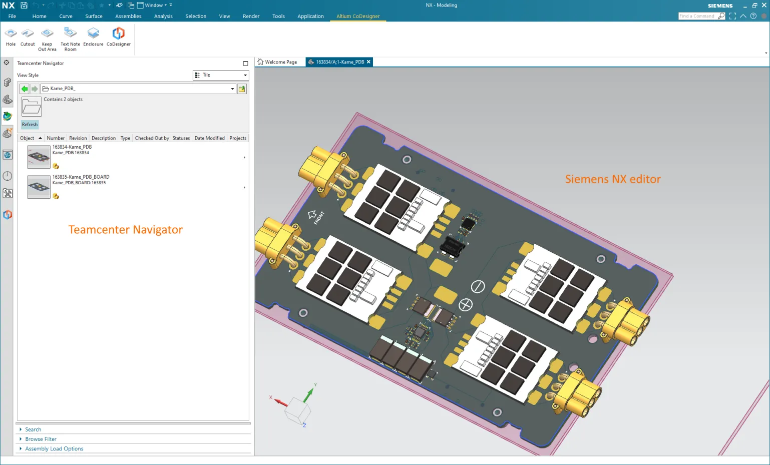 CoDesignerは現在Siemens Teamcenter PLMをサポートしています。
Fusion 360 - 銅とシルクスクリーンの表示
Fusion 360で銅層とシルクスクリーン層を扱うプロセスを簡素化するために、新しい高度なジオメトリ(  )ボタンがFusion 360のAltium CoDesignerリボンに追加されました。このボタンをクリックすると、上部銅層、上部シルクスクリーン層、下部銅層、下部シルクスクリーン層の4つのスケッチ層が表示されます。もう一度クリックすると、これらの層が非表示になります。これらの層は、Fusion 360のオブジェクトブラウザでも選択的に非表示/表示することができます。
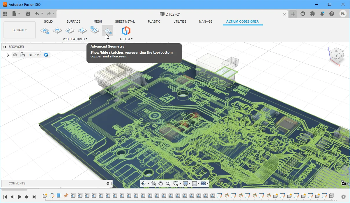 Altium CoDesignerリボンの高度なジオメトリボタンを使用して、上部/下部の銅/シルクスクリーン層をすばやく表示または非表示にします。
Fusion 360とAltium CircuitMakerの間での作業
メーカーコミュニティ向けに開発されたAltium CircuitMakerは、スキーマティックキャプチャとPCBレイアウトを誰でも利用できるようにします。CircuitMakerは、Altium CoDesignerを介してAutodesk Fusion 360にも接続できます。
このCoDesignerのリリースでは、設計を行き来するプロセスがより簡単になりました。ECADから設計を読み込むために、Altium CoDesignerリボンの新しいOpenボタン![]() をクリックします。また、ECADで設計が保存されたときに自動的に通知され、1回のクリックでそれらの変更をFusion 360に取り込むことができます。
をクリックします。また、ECADで設計が保存されたときに自動的に通知され、1回のクリックでそれらの変更をFusion 360に取り込むことができます。
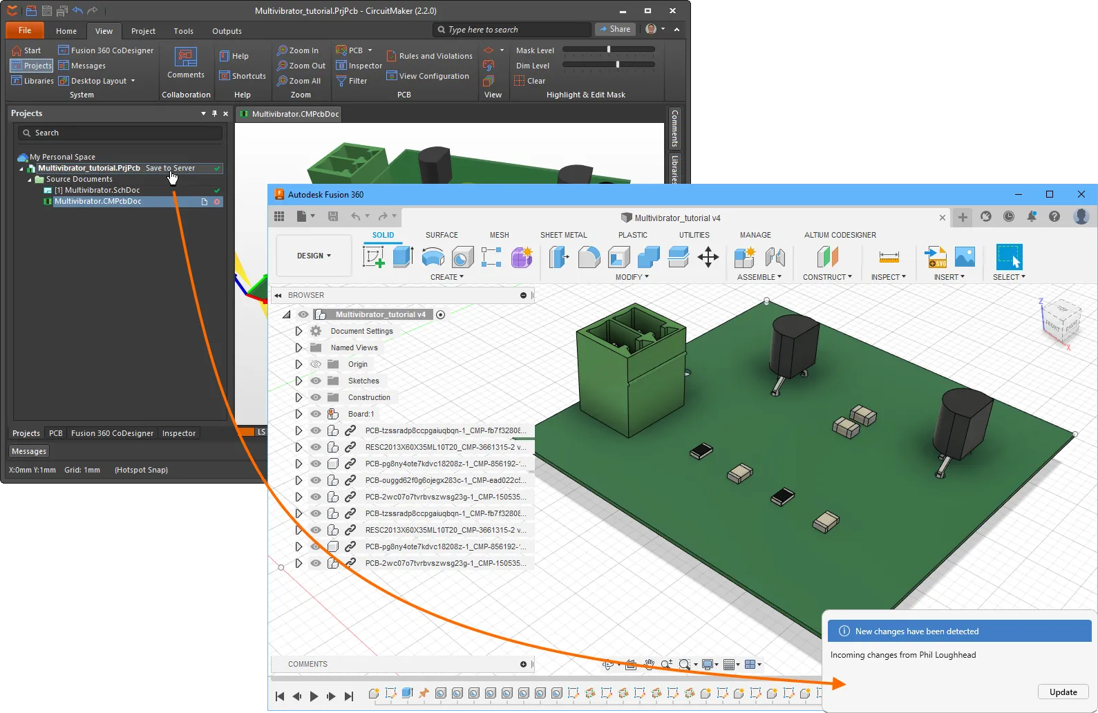 Fusion 360とAltium CircuitMaker間での設計変更の転送が今や簡単になりました。
TRANSLATE:
[折りたたみ 折りたたまれた class="" title="対応バージョン" id="versions_supported_by_codesigner_2-10-0"]
- Altium Designer 21.3(またはそれ以上)でMCAD CoDesigner拡張機能バージョン2.10.0.1555
- Altium NEXUS Client 4.3から5.8まで、MCAD CoDesigner拡張機能バージョン2.10.0.462
- Altium CircuitMaker 2.1(またはそれ以上)でMCAD CoDesigner拡張機能バージョン2.10.0.68
このアップデートは、以下のMCADプラットフォームおよびアドインバージョンでテストされています:
| MCADバージョン |
MCADアドインバージョン |
| Autodesk Inventor Professional® - バージョン2021、2022 |
2.10.0.8 |
| Autodesk Fusion 360® (注1) |
2.10.0.6 |
| Dassault Systemes SOLIDWORKS® - バージョン2020、2021、2022 |
2.10.0.7 |
| PTC Creo Parametric® - 6.X、7.X、8.X |
2.10.0.10 |
| Siemens NX® - バージョン1953以降 (注2) |
2.10.0.11 |
注釈:
- Altium CircuitMakerはAutodesk Fusion 360のみをサポートしています。
- Siemens NXは、エンタープライズソフトウェアサブスクリプションを持つデザイナーのみが利用可能です。
[/折りたたみ]
TRANSLATE:
[折りたたみ 折りたたまれたクラス="" タイトル="リリースノート" id="release_notes_for_codesigner_2-10-0"]
|
MCAD-2646
|
CoDesignerは、Siemens NXと統合されたSiemens Teamcenterと連携して、PCBアセンブリ、PCBパーツ、Siemens NX内のコンポーネントに対する操作を適切に行います。共通コンポーネントフォルダの動作は次のとおりです:CoDesigner設定ダイアログの「ECADからモデルを保存する共通フォルダ」フィールドが空の場合、CoDesignerはTeamcenterリポジトリのルートに「Altium_Components」フォルダを作成し、それを使用します。それ以外の場合は、CoDesignerの「ECADからモデルを保存する共通フォルダ」フィールドに指定されたユーザー定義フォルダが使用されます。
|
|
MCAD-2927
|
Altium NEXUSでは、アクティブなドキュメントとして回路図を開いている状態でMCAD CoDesignerパネルを開くことができました。修正されました。
|
| MCAD-3106 |
Autodesk Fusion 360のCoDesignerリボンに「Advanced Geometry」ボタンが追加されました。クリックすると、PCBの上面と下面の銅とシルクスクリーンを表すスケッチの表示/非表示を切り替えるか、Fusionのオブジェクトブラウザでスケッチの可視性を選択的に制御できます。 |
| MCAD-3228 |
Altium CircuitMakerおよびAutodesk Fusion 360でのCoDesignerのユーザーインターフェースと全体的なユーザーエクスペリエンスが簡素化されました。ECADまたはMCADのCoDesignerパネルにPushおよびPullボタンはもうありません。ECADまたはMCADからAltium 365にPCBを保存すると、自動的に他方で利用可能になり、エンジニアに通知が表示され、Updateをクリックしてエディタに変更を取り込むことができます。初めてFusion 360にPCBデザインを転送するには、Altium CoDesignerリボンの新しいOpenボタンを使用します。注:技術的には、CoDesignerはAltium 365の個人スペースに接続されているときにFusion 360でこのように動作し始めます。従来のインターフェース(PullおよびPushボタン付き)に戻すには、HKEY_CURRENT_USER\SOFTWARE\Altium\CoDesignerのWindowsレジストリキーLegacyPersonalUXに値「1」を設定します。 |
| MCAD-3240 |
ECADにPullする際、CoDesignerはMCADで直径が変更された穴の「Plated」プロパティをリセットしていました。修正されました。 |
| MCAD-3269 |
CoDesignerはSOLIDWORKSのリジッドフレックスボードのスケッチに冗長な制約を作成していました。修正されました。 |
| MCAD-3271 |
ECADでPCBの厚さを変更すると、一部のケースでSOLIDWORKS 2021で「コンポーネントを処理できません」エラーが発生していました。修正されました。 |
[/折りたたみ]
CoDesigner 2.9.0の新機能
リリース日: 2022年3月22日 – バージョン 2.9.0
TRANSLATE:
機能ハイライト
ECADからMCADへの転送から小型コンポーネントを除外
ボード上には、筐体内にPCBを収める際に機械設計者にとって重要でない多くの小型コンポーネントが存在することがよくあります。これを支援するために、コンポーネントの高さに基づいてECADからMCADへの転送から小型コンポーネントを除外する新しいオプションが追加されました。
高さの制限は、MCADのAltium CoDesigner設定ダイアログで設定されます。プルが実行されたときに、高さが<Value><Units>未満のコンポーネントを除外するようにこのオプションを設定します。すべてのコンポーネントを含めるには、このオプションをゼロに設定します。
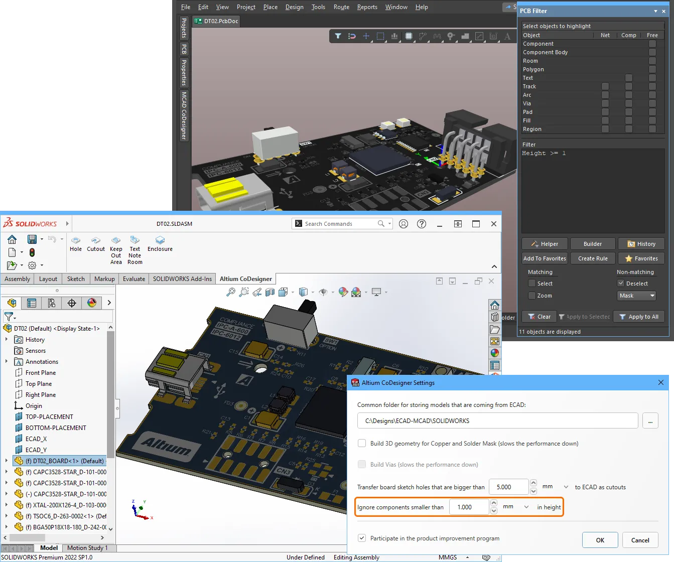 小型コンポーネントはECADからMCADへの転送から除外できます。
ECAD PCBコンポーネントの高さは、PCBライブラリエディター(下の画像の左)またはPCBエディターのプロパティパネル(下の画像の右)で定義されます。これはPCBコンポーネントに含まれる3Dモデルの高さではないことに注意してください。
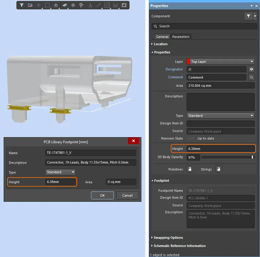 コンポーネントの高さは、PCBライブラリエディターまたはPCBエディターで定義します。
MCADスプラインのサポート
CoDesignerは、ボード形状とカットアウトにおけるスプラインの使用をサポートし、これらの形状をAutodesk Inventor、Autodesk Fusion 360、Siemens NXからECADにプッシュすることができます。PTC CreoおよびSOLIDWORKSでは、すでにスプラインがサポートされていることに注意してください。
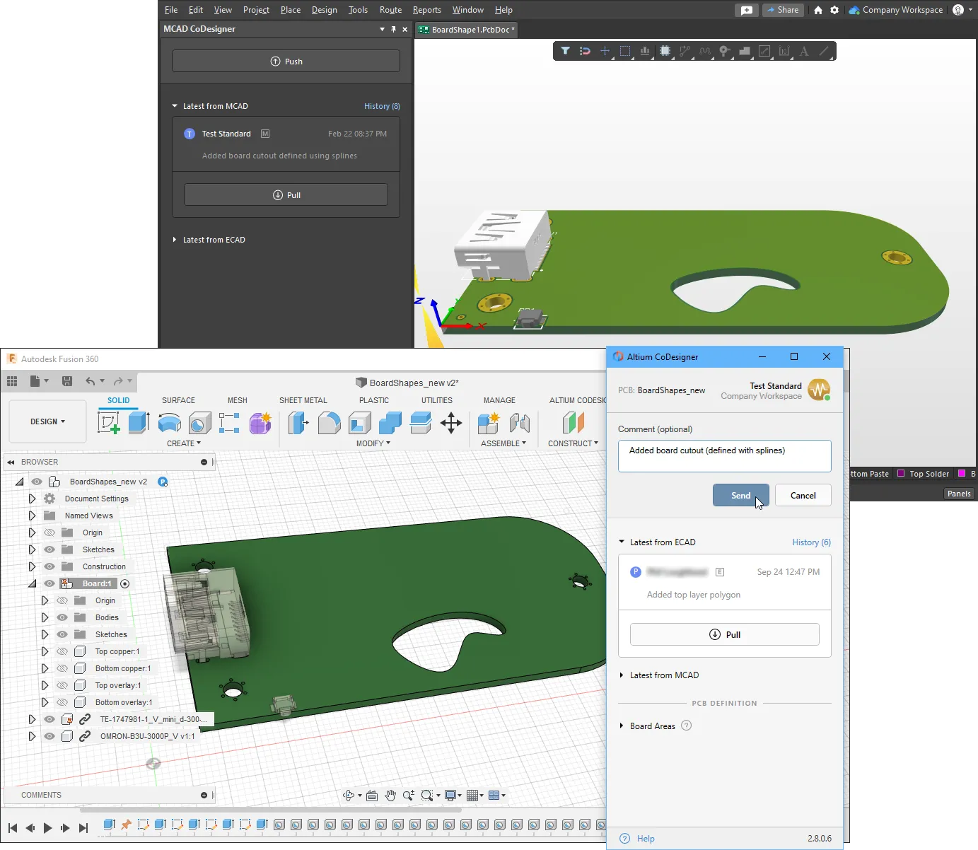 スプラインはMCADからECADにプッシュできます。
スプラインはAltiumの設計ソフトウェアではネイティブの設計オブジェクトではないため、ECADにプルする際に適切なネイティブオブジェクトに変換されます。MCADからのプッシュおよびECADへのプル時に、この変換についてエンジニアに通知する警告が表示されます。例えば、MCADでボードカットアウトを定義する閉じたスプライン形状は、Altiumボードカットアウトリージョンに変換されます。スプラインからリージョンへの変換中に、MCADスプラインによって定義された曲線は、ECADオブジェクトを形成するために複数のポリラインエッジに置き換えられます。その後、そのECADボードカットアウトがMCADにプッシュされると、それはもはやスプラインベースの形状ではありません。元のMCADスプラインを保持するには、下に示すように、MCADへのプル中にそれらをポリラインに変換する形状変更を無効にします。
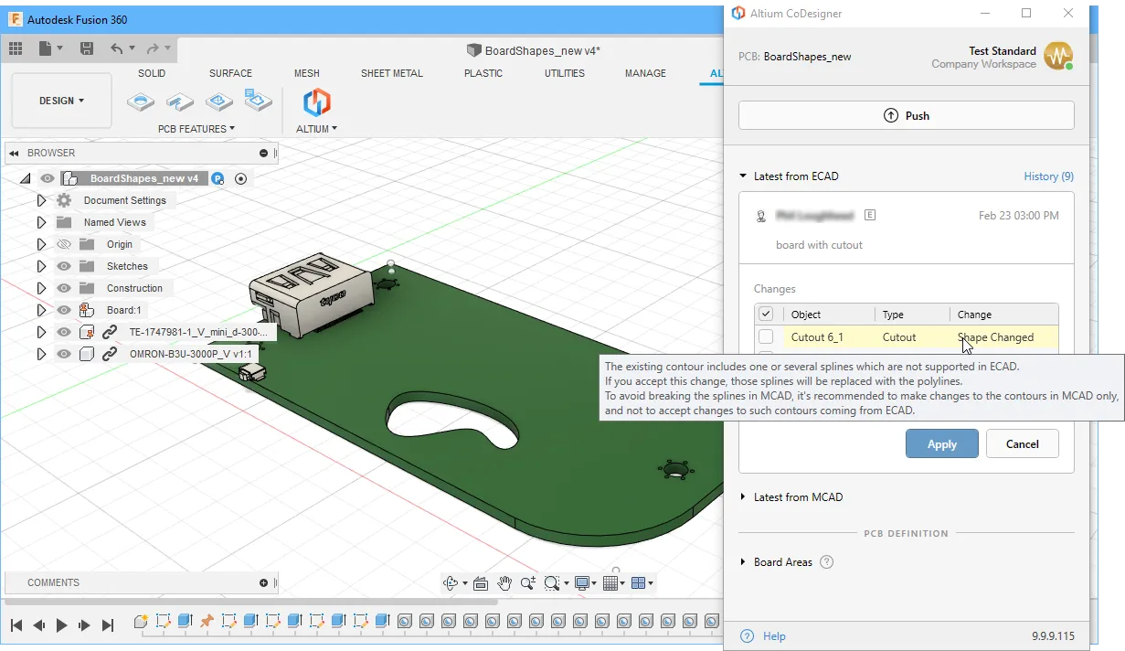 元のMCADスプラインを保持するには、それらをポリラインに変換する形状変更を無効にします。
SOLIDWORKSパーツ構成のサポート
SOLIDWORKS 2020以降は、ボルトやネジなどのパーツの複数の構成を定義することをサポートしています。CoDesignerは、PCB/デバイスアセンブリで使用されている構成可能なパーツのどの構成が使用されているかを検出し、その特定の構成をECADに送信します(以前はデフォルト構成が送信されていました)。
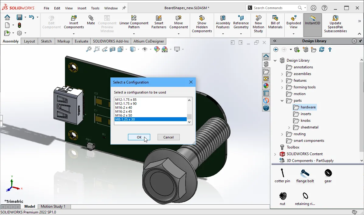 ボード上で使用する特定のSOLIDWORKS構成を選択できるようになりました。
改善されたアークの動作
AltiumのPCB設計ソフトウェアは、アークの位置と半径を定義するためにMCADソフトウェアとは異なるアプローチを使用しているため、ECADのアークとMCADの同じアークの間にわずかな違いが生じる可能性があります。このアップデートでは、ボードジオメトリでアークを扱うアルゴリズムが改善され、ECADのアークとMCADの同じアークの間に違いがないことを保証します。
Siemens NX向けのCoDesignerの改善
Siemens NXは、エンタープライズソフトウェアサブスクリプションを持つ設計者向けにCoDesignerによってサポートされています。
- Siemens NXは変更のプレビューをサポートするようになりました。 Altium CoDesignerパネルの変更リストでアイテムをクリックすると、その変更がワークスペースに表示されます。
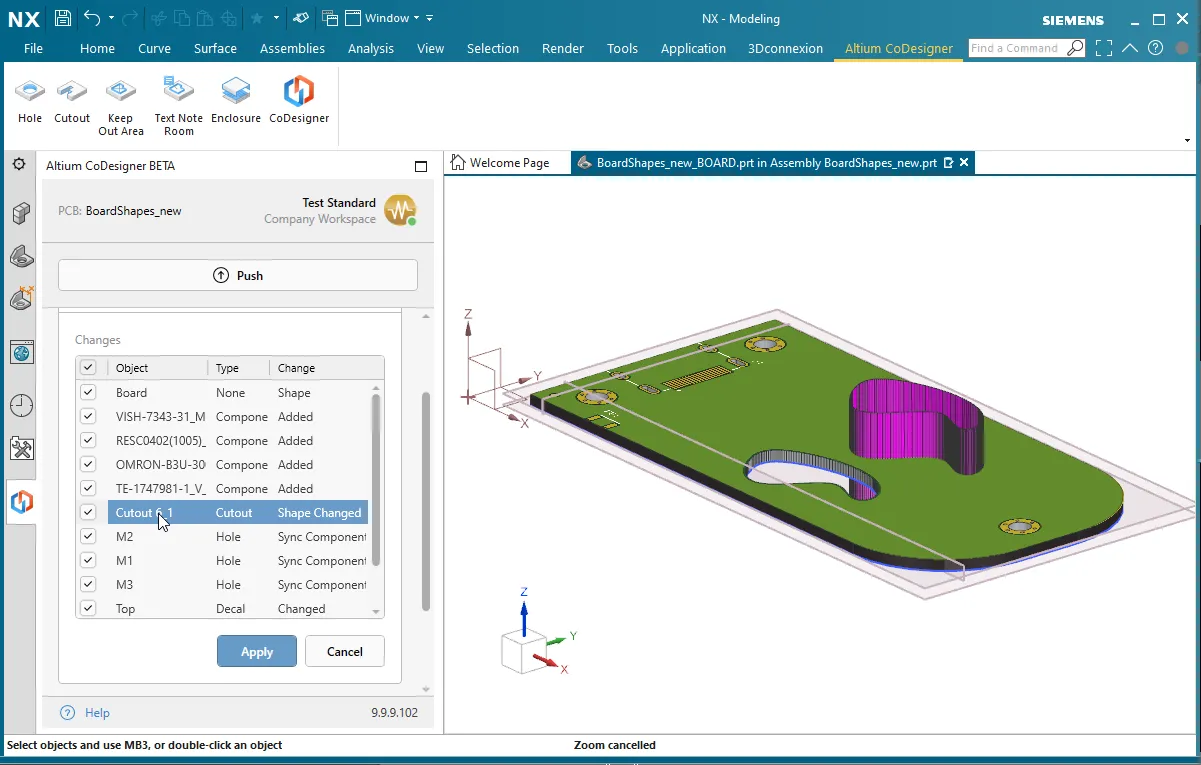 リストの変更をクリックして、その変更がボードに与える影響をプレビューします。
- CoDesignerは、Siemens NXでコンポーネント配置面を表現するようになりました。これらの面は、エンジニアがコンポーネントがはんだマスク層に対してどこに配置されているかを理解するのに役立ちます。
- CoDesignerは、Siemens NXで相対的なECAD原点を表現するようになりました。
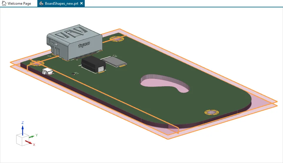 Siemens NXでは、上部および下部の配置面とECAD原点が利用可能です。
TRANSLATE:
[折りたたみ 折りたたまれた class="" title="対応バージョン" id="versions_supported_by_codesigner_2-9-0"]
- Altium Designer 21.3(またはそれ以上)でMCAD CoDesigner拡張機能バージョン2.9.0.1522
- Altium NEXUS Client 4.3から5.8まで、MCAD CoDesigner拡張機能バージョン2.9.0.457
- Altium CircuitMaker 2.1(またはそれ以上)でMCAD CoDesigner拡張機能バージョン2.9.0.57
このアップデートは、以下のMCADプラットフォームおよびアドインバージョンでテストされています:
| MCADバージョン |
MCADアドインバージョン |
| Autodesk Inventor Professional® - バージョン2021、2022 |
2.9.0.14 |
| Autodesk Fusion 360® (注1) |
2.9.0.15 |
| Dassault Systemes SOLIDWORKS® - バージョン2020、2021、2022 |
2.9.0.11 |
| PTC Creo Parametric® - 6.X、7.X、8.X |
2.9.0.12 |
| Siemens NX® - バージョン1953以降 (注2) |
2.9.0.18 |
注釈:
- Altium CircuitMakerはAutodesk Fusion 360のみをサポートしています。
- Siemens NXは、エンタープライズソフトウェアサブスクリプションを持つデザイナーのみが利用可能です。
[/折りたたみ]
TRANSLATE:
[折りたたみ 折りたたまれたクラス="" タイトル="リリースノート" id="release_notes_for_codesigner_2-9-0"]
| MCAD-2309 |
すべてのサポートされているMCADツールに、ECADからMCADへの小型コンポーネントの転送を除外するオプションが追加されました。MCADのCoDesignerの設定で高さ制限を設定します。各コンポーネントの高さはECADプロパティパネルで定義されていますが、PCBコンポーネントに含まれる3Dモデルの高さではありません。 |
| MCAD-2327 |
Autodesk Fusion 360では、CoDesignerがECADではサポートされていない非閉じた輪郭のカットアウトを検出し、ユーザーに警告します。 |
| MCAD-2441 |
SOLIDWORKS 2020以降では、部品の複数の設定を定義することがサポートされています。CoDesignerは、PCB/デバイスアセンブリで使用されている設定可能な部品のどの設定が使用されているかを検出し、その特定の設定をECADに送信するようになりました(以前はデフォルトの設定が送信されていました)。 |
| MCAD-2594 |
Autodesk Fusion 360では、CoDesignerがカットアウトやボードエリアが複数の輪郭から構築されていることを検出し(ECADでは1つの機能あたり1つの輪郭のみがサポートされています)、ユーザーにそれについて警告します。 |
| MCAD-2647 |
Siemens NXでは、変更のプレビューがサポートされるようになりました。CoDesignerパネルのリストで変更をクリックすると、ワークスペースに変更が表示されます。 |
| MCAD-2659 |
機械的エンクロージャ部品の保存とSOLIDWORKSからECADへの送信の準備方法が変更されました。以前は、CoDesignerの設定で共通コンポーネントフォルダに保存されていました。現在は常にMCADのプロジェクトフォルダに保存され、これにより複数の機械エンジニアがエンクロージャを変更し、PDMを使用している場合の競合を防ぐことができます。 |
| MCAD-2727 |
MCADでエンクロージャにボードが挿入され、ECADにプッシュされ、その後MCADでエンクロージャの形状が変更され、再びECADにプッシュされた場合、ECADでエンクロージャがシフトされていました。修正しました。 |
| MCAD-2753 |
CoDesignerでのマルチボードプロジェクトの暫定サポートとして、CoDesignerは他のPCBをデバイスアセンブリに含めることを選択し、それをECADにプッシュすることができるようになりました。 |
| MCAD-2760 |
スプラインはECADではサポートされていないため(複数のポリラインに変換されます)、CoDesignerはプッシュ中にスプラインが検出された場合、機械エンジニアに警告するようになりました。 |
| MCAD-2797 |
PTC Creoでは、CoDesignerがコンポーネントパラメータに「Altium_」プレフィックスを追加しなくなりました。 |
| MCAD-2868 |
Siemens NXでは、CoDesignerが相対的なECAD原点を表現するようになりました(以前に他のMCADで実装されていました)。 |
| MCAD-2869 |
Siemens NXでは、CoDesignerがコンポーネント配置面を表現するようになりました。これらの面は、エンジニアがコンポーネントがはんだマスク層に対してどこに配置されているかを理解するのに役立ちます(以前に他のMCADで実装されていました)。 |
| MCAD-2942 |
Altium Workspaceのユーザーアイコンが、MCADのAltium CoDesignerパネルに表示されるようになりました。 |
| MCAD-3018 |
CoDesignerは、ローカルECADライブラリからMCADに転送されるコンポーネントモデルのオプション名をサポートするようになりました(以前は、Altium 365 Workspaceから配置されたような管理されたECADコンポーネントに対してのみこの機能がサポートされていました)。 |
| MCAD-3041 |
CoDesignerは、ボード形状とカットアウトにスプラインを使用し、Autodesk Inventor、Autodesk Fusion 360、Siemens NXからECADにこれらの形状をプッシュすることをサポートするようになりました(スプラインはPTC CreoとSOLIDWORKSで既にサポートされています)。 |
| MCAD-3043 |
ボードジオメトリでのアークの処理アルゴリズムが改善されました。以前は、ECADとMCADでのアークの定義の違いにより、アークを含むPCBを転送すると、精度の問題やMCADでの制約、特に単位がミリメートルの場合に問題が発生していました。 |
| MCAD-3068 |
管理されていないコンポーネントライブラリについて、CoDesignerはECADで3Dモデルが更新された場合にMCADとの同期を取ることができませんでした。修正しました。 |
| MCAD-3097 |
Siemens NXでは、CoDesignerが同じ部品の複数のインスタンスを機械的エンクロージャとして追加することができませんでした。修正しました。 |
| MCAD-3118 |
ECADからのプッシュ時に、CoDesignerはフットプリント名に双方向制御文字が含まれているコンポーネントの転送ができませんでした。修正しました。 |
| MCAD-3124 |
Autodesk Fusion 360では、CoDesignerがボードアウトライン内の内部スケッチをボードアウトライン全体と誤って解釈していました。修正しました。 |
| MCAD-3184 |
Fusion 360では、特定の条件下でテキストノートやキープアウトエリアを配置した後、それらのエリアがECADに転送されないことがありました。 |
[/折りたたみ]
TRANSLATE:
CoDesigner 2.8.0の新機能
リリース: 2022年2月8日 – バージョン 2.8.0.6 - Autodesk Fusion 360のアップデート
リリース: 2022年1月18日 – バージョン 2.8.0.4 - SOLIDWORKSのホットフィックス
リリース: 2021年12月29日 – バージョン 2.8.0
このリリースには新機能は含まれていません。
サポートされるバージョン
Altium Designer 21.3(またはそれ以上)にMCAD CoDesigner拡張機能バージョン 2.8.0.1472
Altium NEXUS Client 4.3から5.8まで、MCAD CoDesigner拡張機能バージョン 2.8.0.446
このアップデートは以下のMCADプラットフォームとアドインバージョンでテストされています:
| MCADバージョン |
MCADアドインバージョン |
| Autodesk Inventor Professional® - バージョン 2021, 2022 |
2.8.0.3 |
| Autodesk Fusion® |
2.8.0.6 |
| Dassault Systemes SOLIDWORKS® - バージョン 2020, 2021, 2022 |
2.8.0.3 |
| PTC Creo Parametric® - 6.X, 7.X, 8.X |
2.8.0.3 |
| Siemens NX® - バージョン 1953以降(エンタープライズサブスクライバーのみ) |
2.7.0.17 |
CoDesigner 2.8.0.6のリリースノート(Autodesk Fusion 360のアップデート)
| MCAD-2695 |
Autodesk Fusion 360からプッシュする際、CoDesignerは3Dフィレットや面取り、3Dエンティティが構築されていないスケッチなど、サポートされていない機能についてユーザーに警告するようになりました。 |
| MCAD-3083 |
Autodesk Fusion 360でPCBを初めてプルする際、CoDesignerはそのPCBに配置されたコンポーネントの大量の数についてユーザーに通知し、パフォーマンスの問題を避けるために小さなコンポーネントをフィルタリングすることを提案します。 |
CoDesigner 2.8.0.4のリリースノート(SOLIDWORKSのホットフィックス)
| MCAD-3044 |
CoDesignerは、一部のケースでSOLIDWORKSドキュメントからPCB固有の機能を読み取ることができませんでした("GetDocumentFeatures"エラーが表示されました)。修正されました。 |
| MCAD-3045 |
CoDesignerは、SOLIDWORKSのボードアウトラインスケッチで描かれた円を認識できませんでした("Item with same key already added"エラーが表示されました)。修正されました。 |
| MCAD-3047 |
CoDesignerは、一部のケースでSOLIDWORKSの終了を処理できませんでした("On_ActiveDocChangeNotifyEventHandler"エラーが表示されました)。修正されました。 |
TRANSLATE:
[折りたたみ 折りたたまれた class="" title="CoDesigner 2.8.0のリリースノート" id="release_notes_for_codesigner_2-8-0"]
| MCAD-2697 |
CoDesignerは、MCADで認証を使用するプロキシをサポートするようになりました。プロキシのユーザー名とパスワードは、MCADソフトウェアのAltium CoDesignerパネルから設定します。 |
| MCAD-2728 |
PCBグリッドの点は、"MCAD Coordinates"グリッドにはもう描画されません(MCAD原点マークのみが描画されます)。注: "MCAD Coordinates"グリッドは、ボードがMCADで負の座標に移動されたときにECADで描画されます。これにより、PCB上でのスナップに困難を生じさせていたグリッドの点の問題が解決されました。 |
| MCAD-2772 |
ECADまたはMCAD側でミリメートル単位が選択された場合、コンポーネントと穴の座標に微小なずれが生じることがありました。修正されました。 |
| MCAD-2940 |
CoDesignerは、PCBファイル名に次の記号をサポートするようになりました: , (カンマ) ' (シングルクォート) + (プラス)。注1:以前は、これらはMCADにプルする際に _ (アンダースコア)記号に置き換えられていました。注2:PTC Creoはこれらの記号を _ (アンダースコア)記号に置き換え続けます。 |
| MCAD-3024 |
CoDesignerは、モデルの命名スキームが使用できない場合にユーザーに警告します。なぜなら、それによってコンポーネントのリビジョンを判別することが不可能になるからです。 |
[/折りたたみ]
CoDesigner 2.7.0の新機能
リリース日: 2021年11月19日 – バージョン 2.7.0
TRANSLATE:
機能ハイライト
CoDesignerパネルの情報表示の改善
折りたたみ可能な履歴の詳細を導入した最近のCoDesignerパネルの改善を踏まえ、ワークフローを改善するためにCoDesignerパネルが再度アップデートされました。
このアップデートの主な変更点は以下の通りです:
- MCAD CoDesignerパネルにはアクティビティとPCB定義のタブがなくなり、ボードエリアやボードエンクロージャの詳細を含むすべての情報がメインパネルに表示されるようになりました。
- デフォルトでは最新のプッシュとプルのアクションのみが表示され、以前のアクションは履歴リンクをクリックすることでアクセスできます。
- プルボタンは、対応するプッシュ情報の近くに配置されるようになりました。

 更新されたCoDesignerパネルにより、設計変更を追跡しやすくなりました。
シングルサインオンがサポートされるようになりました
シングルサインオン(SSO)は、既存の認証されたサインオンを使用して、ユーザーが異なるサービスにサインインできるアイデンティティ認証システムです。
CoDesignerは現在、シングルサインオンをサポートしており、既存の企業SSOシステムや、GoogleやFacebookアカウントでのサインインが可能です。
 シングルサインオンを使用してワークスペースにサインインできます。
MCADでのECAD相対原点の表示
CoDesignerは現在、MCADで相対ECAD原点(ECADで表示され、ECADエンジニアによって定義される原点)を、XY平面に垂直な2つの平面、ECAD XとECAD Yの形で表示します。ECADの原点が変更されると、それらの平面もMCADでそれに応じて変更されます。
 ECAD原点はMCADで2つの垂直な平面の形で表されます。
SOLIDWORKS 2022のサポート
このリリースのCoDesignerには、SOLIDWORKS 2022のサポートが含まれています。
 CoDesignerは現在、SOLIDWORKS 2022をサポートしています。
Siemens NXのサポート
Siemens NXは、エンタープライズソフトウェアサブスクリプションを持つデザイナー向けにCoDesignerによってサポートされています。このソリューションは当初オープンベータ版で、Siemens NXプラグインはダウンロードページからダウンロードできます。Siemens NXバージョン1953以降がサポートされています。

以下の機能は、このオープンベータ版ではサポートされていません:
- MCADコンポーネントの配置。
- フレックスおよびリジッドフレックスPCB。
- 高度な銅のジオメトリ。
- 変更プレビュー。
- MCADでのECAD原点の表現。
- MCAD側でのAltium PCBの作成機能。
- このバージョンはMCAD PDMシステム(例:Siemens Teamcenter)でのテストは行われていません。
TRANSLATE:
対応バージョン
Altium Designer 21.3(またはそれ以上)にMCAD CoDesigner拡張機能バージョン2.7.0.1434
Altium NEXUS Client 4.3から5.8まで、MCAD CoDesigner拡張機能バージョン2.7.0.435
このアップデートは、以下のMCADプラットフォームおよびアドインバージョンでテストされています:
| MCADバージョン |
MCADアドインバージョン |
| Autodesk Inventor Professional® - バージョン2021、2022 |
2.7.0.13 |
| Autodesk Fusion® |
2.7.0.13 |
| Dassault Systemes SOLIDWORKS® - バージョン2020、2021、2022 |
2.7.0.20 |
| PTC Creo Parametric® - 6.x、7.x、8.x |
2.7.0.14 |
| Siemens NX® - バージョン1953以降(エンタープライズサブスクライバーのみ) |
2.7.0.17 |
TRANSLATE:
[折りたたみ 折りたたまれたクラス="" タイトル="リリースノート" id="release_notes_for_codesigner_2-7-0"]
| MCAD-2308 |
CoDesignerは、ECADで見える原点(ECADユーザーが制御する原点)をMCADで「ECAD X」と「ECAD Y」というXY平面に垂直な2つの平面の形で表示するようになりました。ECADの原点が変更されると、それらの平面もMCADでそれに応じて変更されます。 |
| MCAD-2504 |
MCADで「3D銅を構築」オプションが有効になっている場合、CoDesignerはシルクスクリーンデカールをはんだマスク押し出しの面に適用するようになりました。 |
| MCAD-2620 |
SOLIDWORKS 2022がサポートされるようになりました。 |
| MCAD-2635 |
CoDesignerのユーザーインターフェースが変更されました。主な変更点は以下の通りです:a) MCAD CoDesignerパネルにはもう「アクティビティ」と「PCB定義」のタブがなく、すべての情報はメインパネルに表示されます;b) デフォルトでは最新のプッシュとプルのアクションのみが表示され、以前のアクションは「履歴」ボタン/リンクをクリックすることでアクセスできます;c) プルボタンは対応するプッシュ情報の近くに配置されるようになりました。 |
| MCAD-2636 |
シングルサインオンがサポートされるようになり、GoogleやFacebookアカウントでのサインインが可能になりました。 |
| MCAD-2637 |
PCBプロジェクトが少なくとも1人の機械エンジニアと共有されている場合、CoDesignerはボタンに「プッシュ」と表示するようになり、「プッシュと共有」ではなくなりました。 |
| MCAD-2650 |
Siemens NXがCoDesignerによってサポートされるようになりました。このソリューションは当初オープンベータ版であり、エンタープライズソフトウェアサブスクリプションを持つデザイナーがhttps://www.altium.com/products/downloads#mcad-pluginsからSiemens NXプラグインをダウンロードできます。サポートされるSiemens NXのバージョンは1953以上です。このオープンベータ版の制限事項は以下の通りです:a) MCADコンポーネント配置のサポートなし;b) フレックスおよびリジッドフレックスPCBのサポートなし;c) 高度な銅のジオメトリのサポートなし;d) 変更プレビューなし;e) MCADでのECAD原点の表現なし;f) MCAD側でのAltium PCBの作成ができない。また、このバージョンはMCAD PDMシステム(例:Siemens Teamcenter)とのテストが行われていません。 |
| MCAD-2691 |
NEXUSクライアントの設定から「MCAD CoDesigner」セクションが削除されました。設定にはコンポーネントのプロパティを送信するオプションが含まれていましたが、これらのプロパティは常に送信されるようになりました。 |
| MCAD-2692 |
Creoで「MCADで配置されたモデルを認識する」オプションを使用した場合、CoDesignerはMCADからのバックシンクでECADコンポーネントをフリーの3Dボディに置き換えることを提案しました。修正されました。 |
| MCAD-2713 |
CoDesignerは、ECADからプッシュする際に、部屋やカットアウトのジオメトリがマイクロセグメントのみを含む場合、そのジオメトリの検証に失敗しました。修正されました。 |
| MCAD-2722 |
Windchillへの接続がアクティブな場合、PTC Creoは3D銅エンティティを抑制する際にハングアップしました。修正されました。 |
| MCAD-2748 |
Autodesk Fusion 360では、CoDesignerは初回(新規)プル時にアクティブなドキュメントで作業しようとしましたが、新しいPCBアセンブリを作成する代わりにしました。修正されました。 |
| MCAD-2749 |
Autodesk Fusion 360では、CoDesignerは銅とシルクスクリーンのグラフィックスの中間SVGファイルをプロジェクトフォルダに保存するようになりました(以前は、その情報は共通コンポーネントフォルダに保存されていました)。 |
| MCAD-2778 |
MCADでPCBバリアントがプルされる場合、バリアント名がデフォルトのPCBアセンブリ名に含まれるようになりました。 |
| MCAD-2783 |
Autodesk Fusion 360は、CoDesignerがそのプロジェクトが属するものと異なるワークスペースに接続されている場合、PCBアセンブリを開く際にクラッシュしました。修正されました。 |
| MCAD-2784 |
ECADでの「ボードの移動」操作は、Autodesk Fusion 360で重複したコンポーネント配置平面が作成される結果となりました。修正されました。 |
| MCAD-2794 |
SOLIDWORKSで大きなPCB(1000+コンポーネント)の変更をプルするパフォーマンスが向上しました。 |
| MCAD-2865 |
MCAD側でエンクロージャの部品をPCB定義に追加する際、CoDesignerは対応する通知を表示するようになりました。注:以前は追加の結果が明らかではありませんでした。 |
[/折りたたみ]
TRANSLATE:
CoDesigner 2.6.0の新機能
リリース日: 2021年9月3日 – バージョン2.6.0
TRANSLATE:
機能ハイライト
変更履歴と拒否コメントのサポート
この機能は現在、Altium 365 Workspaceを使用している場合にのみ利用可能です。オンサイトサーバーユーザーの場合は、次のアップデートで利用可能になります。
CoDesignerは現在、承認された変更と拒否された変更の完全な履歴を表示し、変更が拒否された場合にエンジニアが入力したコメントも表示します。変更の履歴はCoDesignerのパネルに表示され、電気エンジニアと機械エンジニア間のやり取りをより透明にします。変更が一方で適用/拒否されると、もう一方のエンジニアに通知され、拒否コメントが表示されます。
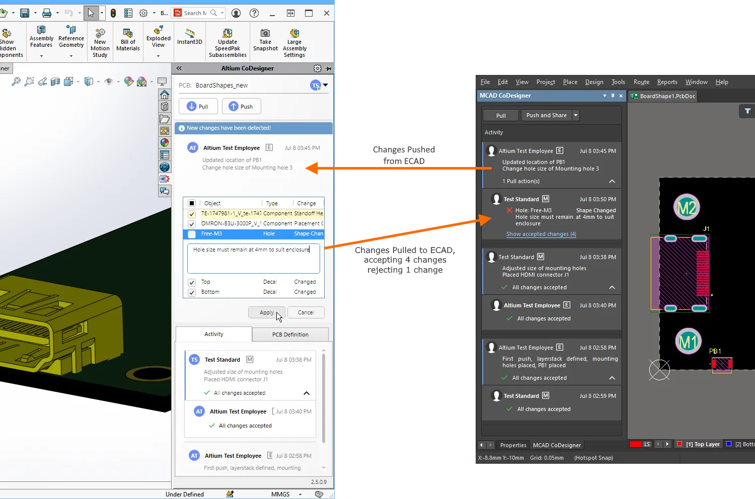 変更履歴により、両側のエンジニアがお互いの変更への対応を把握しやすくなります。
プロジェクトで行われた変更の完全な履歴は、ブラウザを使用してWorkspaceで、またはAltium設計ソフトウェアで表示することもできます。
ブラウザで履歴を表示するには、まずプロジェクトを開き(別のブラウザタブで開きます)、左側のパネルで履歴をクリックします。Altium設計ソフトウェアで履歴を表示するには、メニューからプロジェクト » 履歴 & バージョン管理 » プロジェクト履歴を表示を選択します。
► Altium 365 Workspaceでのプロジェクト履歴についてもっと学ぶ。
 変更履歴はWorkspaceで表示できます。
注: この機能はAltium Designer Standard Subscriptionでは利用できません。
コンポーネントモデルの命名オプション
この機能は現在、Altium 365 Workspaceを使用している場合にのみ利用可能です。オンサイトサーバーユーザーの場合は、次のアップデートで利用可能になります。
CoDesignerは現在、ECADからMCADへの初回転送時にコンポーネントモデルの命名を制御するための4つのオプションを提供しています:
<FootprintName>、次に<ComponentID>(これはデフォルトオプションで、この変更前にどのように機能していたかです)<ComponentID>、次に<FootprintName><FootprintName>、次に<CustomComponentProperty><CustomComponentProperty>、次に<FootprintName>
Workspace SettingsのMCAD CoDesignerセクションでコンポーネントモデルの命名オプションを設定します。
 命名オプションを選択し、カスタムコンポーネントプロパティ(パラメータ)が含まれている場合は、パラメータ名を定義します。
これらの新しいオプションにより、MCADエンジニアはコンポーネントIDに部品番号などの意味のある情報を追加したり、ECADエンジニアはECADコンポーネントライブラリにカスタムコンポーネントプロパティを追加したりすることで、MCADでのコンポーネントとのやり取りが簡単になります。
 MCADモデルは、Workspaceで設定された命名オプションに基づいて名付けられます。
注:
- オプションは、ブラウザでWorkspaceにログインしているときに管理者 > 設定 > MCAD CoDesignerセクションで管理者によって変更できます。
- オプションを変更しても、CoDesignerによって既に作成されたコンポーネントモデルの名前は変更されません。
ボディレスコンポーネントの同期サポート
CoDesignerは現在、複数の穴を持つボディレスコンポーネント(例えば、大きなパッドに囲まれた小さなパッドから作成された取り付け穴コンポーネント)のMCADからECADへの移動を同期することをサポートしています。移動距離と方向は、最大の穴の移動によって定義されます。
Altium NEXUSでのMCADパネルの名前変更
Altium NEXUSのコラボレーションパネルはMCAD CoDesignerパネルに名前が変更されました。その機能はAltium DesignerのMCAD CoDesignerパネルと同じです。
翻訳:
対応バージョン
Altium Designer 21.3(またはそれ以上)でMCAD CoDesigner拡張機能バージョン2.6.0.1377
Altium NEXUS Client 4.3から5.8まで、MCAD CoDesigner拡張機能バージョン2.6.0.412
このアップデートは、以下のMCADプラットフォームおよびアドインバージョンでテストされています:
| MCADバージョン |
MCADアドインバージョン |
| Autodesk Inventor Professional® - バージョン2020、2021、2022 |
2.6.0.8 |
| Autodesk Fusion® |
2.6.0.9 |
| Dassault Systemes SOLIDWORKS® - バージョン2018、2019、2020、2021 |
2.6.0.9 |
| PTC Creo Parametric® - 4.X , 5.X, 6.X, 7.X, 8.X |
2.6.0.9 |
TRANSLATE:
CoDesigner 2.5.0の新機能
リリース日: 2021年7月13日 – バージョン 2.5.0
主な機能のハイライト
はんだマスクの正確な表現
CoDesignerは、Build 3D Copperオプションが有効になっている場合、MCAD内でパッドの開口部を含むはんだマスクの正確なモデルを別のエンティティとして構築します。マスクは銅の間のエッチングされた領域を埋めるため、MCAD内のマスク層の厚さは、ECADで定義された上層銅層とはんだマスク層の厚さの合計です。

SOLIDWORKS内のデカール表示の改善
CoDesignerは、グラフィックスハードウェアによっては半透明のはんだマスクデカールのレンダリングに問題が発生する可能性があるため、SOLIDWORKS内のすべてのデカールを上部デカールと下部デカールの1つに結合します。
 上部デカールは、上部銅層、上部はんだマスク層、および上部シルクスクリーン層の組み合わせです。
注記:
- Build 3D Copperモードが有効になっている場合、シルクスクリーンデカールは生成されません。
- この機能は、Build 3D Copperオプションがこのサブスクリプションレベルでは利用できないため、Altium Designer Standard Subscriptionでは利用できません。
サポートされているバージョン
Altium Designer 21.3(およびそれ以降)にMCAD CoDesigner拡張機能バージョン 2.5.0.1254
Altium NEXUS Client 4.3から5.8まで、Collaborationパネル拡張機能バージョン 2.5.0.362
このアップデートは、以下のMCADプラットフォームおよびアドインバージョンでテストされています:
| MCADバージョン |
MCADアドインバージョン |
| Autodesk Inventor Professional® - バージョン 2020, 2021, 2022 |
2.5.0.11 |
| Autodesk Fusion 360® |
2.5.0.11 |
| Dassault Systemes SOLIDWORKS® - バージョン 2018, 2019, 2020, 2021 |
2.5.0.11 |
| PTC Creo Parametric® - 4.X , 5.X, 6.X, 7.X, 8.X |
2.5.0.11 |
TRANSLATE:
[リリースノート]
| MCAD-2010 |
CoDesignerは、同じコンポーネントの異なるリビジョンがPCB上に配置されている場合、ECADユーザーに警告するようになりました。これは、MCADでモデルの配置を扱う際に問題を引き起こす可能性があります。 |
| MCAD-2115 |
「Build 3D Copper」オプションがONの場合、CoDesignerははんだマスク(パッド用の切り抜きを含む)の正確なモデルをMCAD内で別のエンティティとして構築するようになりました。これにより、PCBのより正確な分析が可能になります。注1:このモードではデカール(特にシルクスクリーン)は表示されません。注2:この機能は、Altium Designer Standard Subscriptionでは利用できません。なぜなら、「Build 3D Copper」オプションはこのサブスクリプションレベルでは利用できないからです。 |
| MCAD-2118 |
CoDesignerは、PTC Creoのカスタムテンプレートと連携するようになりました。 |
| MCAD-2160 |
CoDesignerは、プロジェクトフォルダ内の「-EDM」サブフォルダの名前を10文字に切り詰めていました(ECAD側に位置しています)。これによりナビゲーションが困難になっていました。修正されました(フルパスが128文字以下でない限り、名前は切り詰められません)。 |
| MCAD-2248 |
CoDesignerは、物理的なジオメトリを内包していない部品(例えば、スケルトンモデルとして使用される建設ジオメトリを持つ部品)をMCADからECADに送信しなくなりました。注:以前は、そのような部品がECADに引き込まれた際に非ブロッキングエラーを引き起こしていました。 |
| MCAD-2268 |
SOLIDWORKSのホールウィザードで作成された穴の変更は、ECADで穴のサイズが小さくなった場合、MCADで2回目のプルでのみ適用されていました。修正されました。 |
| MCAD-2284 |
MCADで「自動的にサインイン」オプションがONになっている場合、MCADを閉じてもAltiumのセッション(およびオンサイトインストール用のAltiumのライセンス)が解放されませんでした。修正されました。 |
| MCAD-2288 |
CoDesignerは以前、MCADでPCBアセンブリを作成する際に、プロジェクト名のダッシュをアンダースコア記号に置き換えていました(これは、PTCのルールでモデル名が「-」記号で始まることができないためです)。修正され、"-"記号は最初の1つを除いて置き換えられなくなりました。 |
| MCAD-2297 |
SOLIDWORKSで新しい部品やアセンブリを作成すると、Altium CoDesignerツールバーが自動的に表示されていました。修正されました。 |
| MCAD-2299 |
「Build 3D Copper」オプションがONであるにもかかわらず、PCBにインターレイヤー銅エンティティが存在しない場合、SOLIDWORKSに空の「Interlayer」アセンブリが作成されていました。修正されました。 |
| MCAD-2311 |
ECADでコンポーネントのプロパティに加えられた変更は、コンポーネントの3Dモデルが変更されなかった場合、MCADに転送されませんでした。修正されました。 |
| MCAD-2328 |
Autodesk Fusion 360からECADにボードのアウトラインの楕円が正しく転送されていませんでした。修正されました。 |
| MCAD-2332 |
Autodesk Fusion 360でボードの形状を楕円に変更すると、PCBのルームの形状も楕円に変更されてしまいました。修正されました。 |
| MCAD-2333 |
PTC Creoでボードの形状を円または楕円に再定義しても、ECADで認識されませんでした。修正されました。 |
| MCAD-2336 |
CoDesignerは、SOLIDWORKS内の「ドキュメントが置き換えられたときにコンポーネント名を更新する」オプションを変更していました(過去には、CoDesignerがモデルツリー内でRef Designatorsを表現する際に必要でした)。修正されました(現在は変更されません)。 |
| MCAD-2342 |
CoDesignerは、半透明のはんだマスクデカールのレンダリングに問題が発生する可能性があるグラフィックスハードウェアで、デカールを「トップ」デカールと「ボトム」デカールの1つに結合するようになりました。 |
| MCAD-2354 |
インターネット接続がない場合、MCADプラグインのアップデートチェックを無効にすることができるようになりました。注1:デフォルトでは、CoDesignerはその場合にユーザーに警告しますので、その警告を無効にすることができます。注2:CoDesignerプラグインの設定で、そのオプションを再度ONにすることができます。 |
| MCAD-2377 |
CoDesignerは、PTC Creoで通常の(非フレックス)ボードの「default_dec_places」パラメータを上書きしなくなりました。注:CoDesignerは、リジッドフレックスボードのジオメトリを適切に構築するために、通常の設計に必要以上にそのパラメータの値を設定していました。 |
| MCAD-2390 |
Autodesk Fusion 360用のCoDesignerプラグインのベータステータスが削除されました。 |
| MCAD-2395 |
ユーザーが「AltiumCoDesignerPtcCreo downloads」フォルダを削除した場合、PTC Creo用のCoDesignerプラグインはサーバーからコンポーネントをダウンロードできませんでした。修正されました。 |
TRANSLATE:
CoDesigner 2.4.0の新機能
リリース日: 2021年5月12日 – バージョン2.4.0
TRANSLATE:
対応バージョン
Altium Designer 21.3 および MCAD CoDesigner 拡張機能バージョン 2.4.0.1200
Altium NEXUS Client 4.3 および Collaboration パネル拡張機能バージョン 2.4.0.336
このアップデートは、以下のMCADプラットフォームおよびアドインバージョンでテストされています:
| MCADバージョン |
MCADアドインバージョン |
| Autodesk Inventor Professional® - バージョン 2020, 2021, 2022 |
2.4.0.7 |
| Autodesk Fusion® |
2.4.0.8 |
| Dassault Systemes SOLIDWORKS® - バージョン 2018, 2019, 2020, 2021 |
2.4.0.17 |
| PTC Creo Parametric® - 4.X , 5.X, 6.X, 7.X, 8.X |
2.4.0.13 |
TRANSLATE:
リリースノート
| MCAD-869 |
PTC Creoで変更のプレビューが表示されるようになりました。 |
| MCAD-870 |
Autodesk Inventorで変更のプレビューが表示されるようになりました。 |
| MCAD-1027 |
PTC Creoでは、CoDesignerはエンジニアがCreoで配置したMCADモデルに対してカスタム座標系を使用することをサポートしています(プラグインの設定でこれを有効にするオプションがあります)。ECAD側では、対応するコンポーネントのフットプリントで使用されるモデルは同じ座標系で構築されている必要があります。 |
| MCAD-1529 |
CoDesignerは、SOLIDWORKSユーザーに対して、円形の押し出しカットを検出した場合に警告し、それが穴ではなくカットアウトとして転送されることを警告します。また、SW押し出しカット -> ECADカットアウト、SW穴 -> ECADパッド(円形)について説明しています。 |
| MCAD-1726 |
ECADの内部層に配置されたコンポーネントは、ECADで定義されたオフセットと方向を考慮してMCADに正確に配置されるようになりました(以前は、これらのコンポーネントはMCADの上/下面に調整されていました)。 |
| MCAD-1753 |
ECADで銅層の順序に加えられた変更がMCADに適用されていませんでした。修正されました。 |
| MCAD-1917 |
Fusion 360でボードエリアの高さが一部のケースで誤って設定されていました。修正されました。 |
| MCAD-2044 |
SOLIDWORKS PDMに接続されたSOLIDWORKSで、データ管理システムからネイティブMCADコンポーネントの配置がサポートされるようになりました。注1:MCADコンポーネントは、ECADコンポーネントのパラメータとして "<vault>:folder\folder\component.sldprt" の形式で定義されている必要があります。注2:ECADにPCBをプルする前に、コンポーネントライブラリをローカルPDMストレージと同期する必要があります。 |
| MCAD-2051 |
CoDesignerは、MCAD原点がデフォルトの(絶対的な)ECAD原点と異なる場合、ECADでプルする際に「MCAD座標」グリッド(「MCAD原点」エンティティを含む)を作成します。これにより、電気エンジニアは機械エンジニアとボードのさまざまなエンティティの位置についてコミュニケーションをとるのに役立ちます。注1:「MCAD座標」グリッドの表現はカスタマイズ可能です。注2:MCADでのECAD原点の表現も近々実装される予定です。 |
| MCAD-2067 |
Autodesk Fusion 360では、CoDesignerは小さなコンポーネントを無視するオプションを提供するようになりました(サイズ制限はカスタマイズ可能です)。これにより、500以上のコンポーネントが配置されたボードのパフォーマンスが向上します。 |
| MCAD-2082 |
PTC Creo 8が正式にサポートされるようになりました。 |
| MCAD-2107 |
CoDesignerは、Windchillでそのテンプレートが見つからない場合、PTC Creoで自動的にシートメタルテンプレートを作成するようになりました。 |
| MCAD-2119 |
Autodesk Fusion 360で変更のプレビューが表示されるようになりました。 |
| MCAD-2127 |
ボードの輪郭にマイクロセグメントの問題を自動的に修正する機能が追加されました(ユーザーの確認に基づきます)。この機能は新しいAPIを利用しているため、AD 21.3.XまたはAN 4.3.X以降でのみ利用可能です。 |
| MCAD-2133 |
ECADのリジッドフレックス層スタックでOFFにされた中間層が、MCADでのボードの厚さに誤って含まれていました。修正されました。 |
| MCAD-2156 |
PTC Creoでのコンポーネント名の最大長が24文字から31文字に増加しました。注:以前は、残りの文字はコンポーネントリビジョン用に予約されていましたが、現在はリビジョン用の文字がコンポーネント名の全体の長さから差し引かれます。 |
| MCAD-2170 |
CoDesignerは、ボードの上面と下面に同じジオメトリで2つのエリアが作成された場合(「オブジェクト参照がオブジェクトのインスタンスに設定されていません」と表示される)、ボードエリア(キープアウト、ルーム)を識別できませんでした。修正されました。 |
| MCAD-2183 |
Autodesk Inventor 2022が正式にサポートされるようになりました。注:Autodesk Inventor 2019はもうサポートされていません。 |
| MCAD-2211 |
CoDesignerは、PTC Creoで作成されたPCBの精度のタイプ(絶対または相対)を選択することをサポートするようになりました。 |
| MCAD-2215 |
CoDesignerのパネルを開くボタンがAutodesk Fusion 360のツールバーに直接追加され、パネルを開くことが簡単になりました。 |
| MCAD-2242 |
CoDesignerは、PCBアセンブリにゼロジオメトリのパーツが追加された場合、MCADからPCBをプッシュすることをブロックしていました。修正されました。 |
| MCAD-2298 |
Autodesk Fusion 360で「小さなコンポーネントを無視する」オプションがONの場合、CoDesignerは時々ECADにPCBをプッシュバックすることに失敗し、「インデックスが範囲外です」という内部エラーが発生しました。修正されました。 |
| MCAD-2303 |
CoDesignerは、SOLIDWORKSでプルする際に、以前にECADから転送されたモデルにユーザーまたはPDMシステムによって割り当てられたカスタムMCADコンポーネントプロパティ(プロパティ)を削除していました。修正されました。 |
TRANSLATE:
CoDesigner 2.3.0の新機能
リリース日: 2021年3月22日 – バージョン2.3.0
TRANSLATE:
対応バージョン
Altium Designer 21.x with MCAD CoDesigner 拡張機能バージョン 2.3.0.1127
Altium Designer 20.2 with MCAD CoDesigner 拡張機能バージョン 2.3.0.1127
Altium NEXUS Client 4.x with Collaboration パネル拡張機能バージョン 2.3.0.324
Altium NEXUS Client 3.2 with Collaboration パネル拡張機能バージョン 2.3.0.324
このアップデートは、以下のMCADプラットフォームおよびアドインバージョンでテストされています:
| MCADバージョン |
MCADアドインバージョン |
| Autodesk Inventor Professional® - バージョン 2019, 2020, 2021 |
2.3.0.8 |
| Autodesk Fusion® |
2.3.0.8 |
| Dassault Systemes SOLIDWORKS® - バージョン 2018, 2019, 2020, 2021 |
2.3.0.9 |
| PTC Creo Parametric® - 4.X , 5.X, 6.X, 7.X |
2.3.0.22 |
TRANSLATE:
リリースノート
|
MCAD-916
|
CoDesignerは、SOLIDWORKS内のボード部品ファイルに直接デカール(銅、シルクスクリーン、はんだマスクを表す画像)を保存するようになりました。これにより、MCAD側でPDMシステムを使用している場合のPCB関連ファイルの管理が簡素化されます。
|
|
MCAD-1505
|
リジッドフレックスボード上のコンポーネントアセンブリ用の座標系が、SOLIDWORKS 2018、2019の一部のケースで誤って作成されていました。修正しました。
|
|
MCAD-1710
|
CoDesignerは、ECADから定義されているすべてのPCBバリアント(定義されている場合)を送信するようになりました。これまではアクティブなバリアントのみでした。MCAD側では、新しい「ボードをプル」ダイアログで必要なバリアントを選択する必要があります。
|
|
MCAD-1844
|
MCADにPCBをプルするために使用されるダイアログが変更されました。これで、次のものが表示されます:PCBのプレビュー(対応するPCBプロジェクトがECADからサーバーに保存されている場合)、ECADからの最新のプッシュに関する情報(プッシュされている場合)、PCBバリアント(存在する場合)。
|
|
MCAD-1847
|
「ビアを構築」オプションがONの場合、MCADで新しいプロジェクトを開始したときにボード部品が作成されませんでした。修正しました。
|
|
MCAD-1860
|
CoDesignerは、Autodesk InventorでParasolid変換アドインを見つけることができず(そしてそれに応じてコンポーネントモデルを構築することができず)、サードパーティのアドインのいくつかがリクエストのタイプに正しく応答していない場合がありました。修正しました。
|
|
MCAD-1876
|
リジッドフレックスボード転送:分割線と曲げエリアの間の最小許容距離が2.5ミルから0.5ミルに減少しました。
|
|
MCAD-1937
|
Autodesk Fusion 360 MCADがCoDesignerによってサポートされるようになりました(ソリューションは当初オープンベータ版です)。Autodesk Fusion 360用のプラグインは、https://www.altium.com/products/downloads#mcad-pluginsからダウンロードできます。注1:「PROサブスクリプション」機能(MCADコンポーネント配置、リジッドフレックスボードサポート、押し出された銅、エンクロージャ交換)は現在サポートされていません。注2:銅とシルクスクリーンの表現は、他のMCADで実装されているものとは異なり、裸のボード部品内のスケッチのみに基づくコンポーネントによって表されます(これらのコンポーネントはデフォルトで非表示になっており、ユーザーはそれらを表示にして、必要に応じて押し出しや押し出された表面などの3D機能を追加的に構築できます)。注3:このベータ版では、MCAD側で500以上のコンポーネントを含むPCBを初めてプルする際に、一部のパフォーマンスの問題が発生する可能性があります。これらの問題は次のバージョンで対処される予定です。
|
|
MCAD-1945
|
リジッドフレックスボードの同期がPTC Creoでもサポートされるようになりました(ソリューションは当初ベータモードです)。現在サポートされていない機能:1. MCAD側での新しい領域と新しい曲げの追加、2.「リジッドフレックス2.0」機能で導入された新機能。
|
|
MCAD-1946
|
CoDesignerは、PTC CreoでAbsolute Accuracyプロパティを上書きしなくなりました。
|
|
MCAD-2006
|
PTC Creoで、丸みを帯びたまたは円形のボードの場合、デカール(銅、シルクスクリーン、はんだマスクを表す画像)が正しくスケールされていませんでした。修正しました。
|
|
MCAD-2035
|
CoDesignerのバージョンが、MCAD内のAltium CoDesignerパネルの右下隅に直接表示されるようになりました。
|
|
MCAD-2050
|
MCADで構築されたボードエリア(キープアウト、ルーム)のデフォルトの高さが1mmから0.5mmに減少しました。これにより、視界を遮らず、小さなコンポーネントを選択するのが難しくなることを防ぎます。
|
|
MCAD-2073
|
Altiumサーバーで行われた変更により、MCAD側の「プルするPCBを選択」ダイアログでプロジェクト名が誤ってプロジェクトIDに置き換えられていました。修正しました。
|
|
MCAD-2077
|
CoDesignerは、ECADのレイヤースタック内のレイヤーの命名に重複があることを検出し、対応するエラーメッセージを表示するようになりました。
|
| MCAD-2175 |
MCADプラグインが一部のケースでAltium 365に接続できないことがありました。修正しました。 |
TRANSLATE:
CoDesigner 2.2.0の新機能
リリース日: 2021年1月13日 – バージョン 2.2.0
TRANSLATE:
機能のハイライト
MCADからECADへのエンクロージャのプッシュ
このアップデートでは、MCADでデバイスアセンブリレベルでの作業をサポートし、ボードと共にエンクロージャをECADに転送する機能が追加されました。以下のビデオは、ボードアセンブリをデバイスエンクロージャに含め、エンクロージャをAltium設計ソフトウェアに転送するプロセスを示しています。
► このオプションは、Altium Designer Standard Subscriptionでは利用できないことに注意してください。Standardサブスクリプションを持つデザイナーは、このビデオを見て、エンクロージャを転送する別の方法を確認できます。
このビデオは、Altium Designerを使用したCoDesignerの機能を示しています。Altium NEXUSとMCADソフトウェア間のCoDesignプロセスは同じですが、古いバージョンのAltium NEXUSでは、MCAD CoDesignerパネルではなく、Collaborationパネルを使用します。
CreoにCoDesignerリボンが追加されました
PTC CreoにAltium CoDesignerリボンが追加されました(リボンはすでにSOLIDWORKSとAutodesk Inventorで利用可能です)。リボンは、MCAD-ECAD CoDesignプロセス中に一般的なPCB固有の設計オブジェクトに簡単にアクセスする方法を提供します。リボンボタンを使用して、互換性のあるECADオブジェクトを作成するために正しいMCADオブジェクトタイプが使用されることを確認します。

コンポーネント配置用の新しいMCADプレーン
CoDesignerは、MCADでトップとボトムサイドのコンポーネントプレーンを作成するようになり、MCADでのコンポーネントの配置が簡単になりました。コンポーネントは、はんだマスク層の厚さを無視して配置されるようになりました。
ビアとパッドの銅バレルのサポート

- パッドバレル - Build 3D geometry for CopperがAltium CoDesigner設定ダイアログで有効になっている場合、スルーホールパッドバレルがECADからMCADに転送されます。
- ビアバレル - Build Viasオプションも有効にして、ビアバレルを含めます。

 ビアとパッドの銅バレルは常にECADからプッシュされます(左の画像)、MCADでそれらをプルするかどうかは、上記のCoDesignerオプションを使用して制御します(右の画像)。
簡素化されたCoDesignerパネル
CoDesignerメニューは更新され、以前はAltium CoDesignerパネルの表面にあったヘルプと設定オプションが含まれるようになりました。

KeepoutsとRoomsのサポートが向上
CoDesignerは、ECADでのKeepoutsとRoomsのロック状態を検出し、MCADからのプル中にこれらが移動しないようにします。
TRANSLATE:
対応バージョン
Altium Designer 21.0 に MCAD CoDesigner 拡張機能バージョン 2.2.0.1072
Altium Designer 20.2 に MCAD CoDesigner 拡張機能バージョン 2.2.0.1072
Altium NEXUS Client 4.0 に Collaboration パネル拡張機能バージョン 2.2.0.310
Altium NEXUS Client 3.2 に Collaboration パネル拡張機能バージョン 2.2.0.310
このアップデートは、以下のMCADプラットフォームおよびアドインバージョンでテストされています:
| MCADバージョン |
MCADアドインバージョン |
| Autodesk Inventor Professional® - バージョン 2019, 2020, 2021 |
2.2.0.6 |
| Dassault Systemes SOLIDWORKS® - バージョン 2018, 2019, 2020, 2021 |
2.2.0.7 |
| PTC Creo Parametric® - 4.X , 5.X, 6.X, 7.X |
2.2.0.6 |
TRANSLATE:
[折りたたみ 折りたたまれたクラス="" タイトル="リリースノート" id="release_notes_for_codesigner_2-2-0"]
| MCAD-400 |
CoDesignerは、PCBアセンブリに切り替えることなく、MCADのデバイスのコンテキストでPCBを操作することをサポートするようになりました。これにより、PCB定義とエンクロージャー間の作業が格段に容易になります。1つのデバイスに複数のPCBがある場合、CoDesignerはそれらの間での切り替えをサポートします。 |
| MCAD-786 |
CoDesignerは、設定で「3D銅」オプションが有効になっている場合、MCADでメッキスルーホールパッドの銅バレルを構築するようになりました(このオプションは熱シミュレーションに必要です)。 |
| MCAD-796 |
CoDesignerは、MCADでビアの銅バレルを構築するようになりました(ビアの銅とボードを通る穴の正確な3Dジオメトリ)。注:MCADからECADへのビアの変更の転送はサポートされていません。 |
| MCAD-987 |
MCAD側の「PCBプロジェクトを選択」ダイアログでのプロジェクト検索が大文字小文字を区別しないようになりました。 |
| MCAD-1531 |
CoDesignerのアイコンが4Kモニターをサポートするようになりました。 |
| MCAD-1586 |
CoDesignerは、ECADからのプッシュ時にマイクロアークを検証するようになりました(以前に実装されたマイクロセグメントの検証とともに)。 |
| MCAD-1607 |
PTC Creoのソリューションには、PCB定義に関連するコマンドを含むCoDesignerのツールバーが含まれるようになりました。 |
| MCAD-1609 |
CoDesignerは、MCADからECADへのPCBエンクロージャーの部品の送信をサポートするようになりました(MCAD-400も参照)。ユーザーは、MCADのCoDesignerのリボンツールバーに新しく追加された「エンクロージャー」ボタンをクリックして、これらの部品を選択できます。 |
| MCAD-1652 |
MCADのCoDesignerパネルに「更新」ボタンが追加されました。このボタンをクリックすると、CoDesignerは現在開いているデバイスアセンブリに存在するボードアセンブリを検出します。MCAD-400も参照してください。 |
| MCAD-1679 |
内部プレーン層は、ECADからMCADに転送されず、3D銅オプションに含まれていませんでした。修正されました。 |
| MCAD-1689 |
MCADでのボードエリアプロパティの更新のパフォーマンスが向上しました。 |
| MCAD-1693 |
CoDesignerは、はんだマスク層の厚さを無視してMCADでコンポーネントを配置するようになりました。以前にMCADでプルされたPCB上のコンポーネントについては、CoDesignerは最初の更新時に「スタンドオフ高さ調整」の変更を表示します。さらに、CoDesignerはMCADで上部と下部のコンポーネント配置用に2つの追加の平面を作成するようになりました。これらの平面の目的は、機械エンジニアが新しいコンポーネントの正確な配置を支援し、既存のコンポーネントの配置の変更を行うことを支援することです。 |
| MCAD-1694 |
リジッドフレックスボード上のコンポーネントが、場合によっては間違ったオフセットで配置されていました。修正されました。 |
| MCAD-1697 |
CoDesignerは、MCADでのコンポーネントのスタンドオフ高さの変更を(ECADで設定された値に従って)別の変更タイプとして考慮するようになりました(以前は「配置変更」に含まれていました)。 |
| MCAD-1703 |
ECADへのプル時にロックされたキープアウトとルームの移動と削除がブロックされるようになりました。これにより、電気エンジニアはMCAD側で「電気」ボードエリアに対する偶発的な変更を防ぐことができます。 |
| MCAD-1731 |
Altium 365ユーザー向けのCoDesignerの機能は、「PRO」と「STD」の機能セットに分割され、Altium 365アカウントのタイプに応じて提供されます。以下の高度な機能はPROユーザーのみが利用できます:
a) MCAD主導のコンポーネント配置、
b) リジッドフレックスボードのサポート、
c) MCADでの3D銅とビアの構築、
d) デバイスアセンブリのコンテキストからのエンクロージャー交換。 |
| MCAD-1824 |
CoDesignerはもはや、SOLIDWORKSドキュメントに組み込まれたテーブルがサポートされていないというSOLIDWORKSユーザーに警告しません。 |
[/折りたたみ]
TRANSLATE:
CoDesigner 2.1.0の新機能
リリース日: 2020年11月20日 – バージョン 2.1.0
TRANSLATE:
対応バージョン
Altium Designer 20.2 および MCAD CoDesigner 拡張機能バージョン 2.1.0.1033
Altium NEXUS Client 3.2 および Collaboration パネル拡張機能バージョン 2.1.0.302
このアップデートは、以下のMCADプラットフォームおよびアドインバージョンでテストされています:
| MCADバージョン |
MCADアドインバージョン |
| Autodesk Inventor Professional® - バージョン 2019, 2020, 2021 |
2.1.0.6 |
| Dassault Systemes SOLIDWORKS® - バージョン 2018, 2019, 2020, 2021 |
2.1.0.7 |
| PTC Creo Parametric® - 4.X , 5.X, 6.X, 7.X |
2.1.0.10 |
TRANSLATE:
CoDesigner 2.0.5の新機能
リリース日: 2020年9月18日 – バージョン2.0.5
TRANSLATE:
対応バージョン
Altium Designer 20.2 および MCAD CoDesigner 拡張機能バージョン 2.0.5.885
Altium NEXUS Client 3.2 および Collaboration パネル拡張機能バージョン 2.0.5.284
このアップデートは、以下のMCADプラットフォームおよびアドインバージョンでテストされています:
| MCADバージョン |
MCADアドインバージョン |
| Autodesk Inventor Professional® - バージョン 2019, 2020 |
2.0.5.52 |
| Dassault Systemes SOLIDWORKS® - バージョン 2018, 2019, 2020 |
2.0.5.68 |
| PTC Creo Parametric® - 4.X , 5.X, 6.X, 7.X |
2.0.5.60 |
TRANSLATE:
リリースノート
| MCAD-1098 |
CoDesignerは、ECADからMCADへ、そしてその逆へのPCBバリアントの同期が可能になりました。バリアントは一つずつ同期でき、MCADで製品構成を作成する必要はありません(CoDesignerは現在同期中のバリアントを表示します)。 |
| MCAD-1167 |
Altium NEXUSのコラボレーションパネルからの警告メッセージに誤ったヘッダーが表示されていました。修正しました。 |
| MCAD-1168 |
CoDesignerは、同期を行った後にユーザーが長い休憩を取った場合の混乱を避けるため、ECADでのプッシュとプルのアクションの絶対時間を報告するようになりました。 |
| MCAD-1185 |
CoDesignerは、問題のある点の座標をボードで使用されている単位で表示するようになりました(以前は常にミルで表示されていました)。 |
| MCAD-1228 |
リジッドフレックスボードのサポート:CoDesignerは、ECADからプッシュする際にスプリットラインの一方の端がカットアウトに覆われている状況(これは、MCADでコンポーネントアセンブリを適切に結合するために使用される座標系が正しく作成されない可能性が高いことを意味します)を検出し、ユーザーに警告します。 |
| MCAD-1252 |
CoDesignerは、フットプリントにインポートされた単一ボディのParasolidモデルを、変換せずに、変形せずにMCADに転送するようになりました。これにより、場合によってはこれらのステップで発生する可能性のあるモデルの破損を回避できます。 |
| MCAD-1287 |
CoDesignerは、プッシュのたびにサーバーのMCADコンポーネント配置設定を読み取るようになったため、設定を変更した後にECAD/MCADソフトウェアを再起動する必要がなくなりました。 |
| MCAD-1346 |
リジッドフレックスボードのサポート:CoDesignerは、フレックスセグメント上に配置され、ボディレスコンポーネントによって表されるパッドの移動の同期を可能にしました。 |
| MCAD-1424 |
ECADからのプル時、CoDesignerはデザインエータがないコンポーネントを報告するようになりました。 |
| MCAD-1452 |
Inventor 2020からECADへのフリー3Dボディが、使用されているParasolidのモダンバージョンのために送信されませんでした。修正しました。 |
| MCAD-1464 |
CoDesignerによってPTC Creoで誤って設定された公差設定がありました。CoDesignerはこれらの設定を行わないようにしました。 |
| MCAD-1476 |
MCADでボードの底面に初めて配置されたコンポーネントに対して、MCADの変更テーブルで配置変更が誤って表示されていました。修正しました。 |
| MCAD-1477 |
場合によっては、MCAD側でボードの底面に配置されたフリー3Dボディのプル時に、ECADで誤ったスタンドオフ高さが定義されていました。修正しました。 |
| MCAD-1485 |
UI:「ヘルプ」ボタンがMCADのCoDesignerパネルの上部に移動しました。 |
| MCAD-831 |
CoDesignerは、PTC Creoでボードアウトラインを読み取ることができませんでした。このアウトラインは、親アセンブリにある部品への参照として作成されたものです(例えば、エンクロージャからのオフセットとして作成されたアウトライン)。修正しました。 |
| MCAD-854 |
MCADでの3Dモデルの変更がECADと同期されず、その逆も同様でした。修正しました。 |
| MCAD-903 |
CoDesignerは、ボードアウトラインの外側に中心が位置する穴をMCADでカット押し出しとして作成するようになり、MCADでの不正な動作を避けることができます。 |
TRANSLATE:
CoDesigner 2.0.4の新機能
リリース日: 2020年6月24日 – バージョン 2.0.4
主な機能のハイライト
MCADでのリジッドフレックス基板の定義
リジッドフレックスのサポートが大幅に改善されました – 基板の形状と曲げ定義は、SOLIDWORKS®で定義および変更することができ、SOLIDWORKSでコンポーネントを配置および移動することができます。(PTC Creo®およびAutodesk Inventor®でのリジッドフレックスサポートは、将来のアップデートで提供予定です)
 基板の形状と曲げ定義は、SOLIDWORKSで定義および変更することができます。
► リジッドフレックス基板の同期についての詳細はこちら
複雑な基板形状のサポートが強化
基板形状定義の問題に対するサポートが改善されました – ECAD基板スケッチのマイクロセグメントと自己交差が検出され、プッシュ時に報告されます。それらの位置は詳細に記載され、可能な場合はMCADで自動的に修正されます。

► MCADで解決できない問題については、ECADでの基板輪郭の問題解決についての詳細をご覧ください
コンポーネント同期の改善
ロックされたコンポーネントの取り扱いが簡素化されました – 固定または制約されたMCADパーツは、ECADでロックされたコンポーネントに変換され、ECADでロックされたものはMCADで固定されます。ロック/固定状態の変更は、MCADとECAD間で同期されます。
ECADコンポーネントのプロパティがMCADに転送されます – すべてのECAD PCBコンポーネントパラメータがMCADパーツに転送されます。
 ECAD PCBコンポーネントのパラメータが同等のMCADパーツに転送されます。
サポートされるバージョン
Altium Designer 20.2 および MCAD CoDesigner 拡張機能バージョン 2.0.4.829
Altium NEXUS Client 3.2 および Collaboration パネル拡張機能バージョン 2.0.4.272
このアップデートは、以下のMCADプラットフォームおよびアドインバージョンでテストされています:
| MCADバージョン |
MCADアドインバージョン |
| Autodesk Inventor Professional® - バージョン 2019, 2020 |
2.0.4.45 |
| Dassault Systemes SOLIDWORKS® - バージョン 2018, 2019, 2020 |
2.0.4.62 |
| PTC Creo Parametric® - 4.X , 5.X, 6.X, 7.X |
2.0.4.53 |
TRANSLATE:
CoDesigner 2.0.3の新機能
リリース日: 2020年5月22日 – バージョン 2.0.3
主なハイライト
複雑なボード形状とコンポーネントのサポートが強化
このリリースでは、Altiumの設計ソフトウェアとお気に入りのMCAD設計ソフトウェア間でのPCBデザインの受け渡しを大幅に改善しました。

このサポートには以下が含まれます:
- 切り抜きを含む複雑なボード形状の双方向転送
- 配置されたコンポーネントを3Dモデルとしての双方向転送
- MCADからECADへのネイティブコンポーネントの転送
- ECADからMCADへのネイティブコンポーネントの転送(Creoのみ)
- リジッドフレックスPCBのサポート(SOLIDWORKSのみ)
サポートされるバージョン
Altium Designer 20.1 および MCAD CoDesigner 拡張機能バージョン 2.0.3.721
Altium NEXUS Client 3.1 および Collaboration パネル拡張機能バージョン 2.0.3.255
このアップデートは以下のMCADプラットフォームとアドインバージョンでテストされています:
| MCADバージョン |
MCADアドインバージョン |
| Autodesk Inventor Professional® - バージョン 2019, 2020 |
2.0.3.27 |
| Dassault Systemes SOLIDWORKS® - バージョン 2018, 2019, 2020 |
2.0.3.30 |
| PTC Creo Parametric® - 4.X , 5.X, 6.X |
2.0.3.31 |
リリースノート
| MCAD-983 |
SolidWorksが時々クラッシュすることがありました。これらのクラッシュのほとんどの原因が見つかり、修正されました。 |
| MCAD-1107 |
トップソルダーマスクとボトムソルダーマスクのデカールが、SolidWorks 2019-では表示され、SolidWorks 2020+では非表示になるように適用されます。注:以前はSolidWorks 2020でのレンダリングの問題のため、これらのデカールの適用が無効にされていました。現在、ユーザーはSolidWorks 2020+で手動でそれらを表示にすることができ、必要に応じて外観を調整できます。 |
| MCAD-1170 |
MCAD側でボードが作成された場合、Autodesk Inventorがクラッシュすることがありました。修正されました。 |
| MCAD-1180 |
サーバーに送信されるモデルは、スペースを節約し、パフォーマンスを向上させるためにパックされるようになりました。 |
| MCAD-1186 |
UIの変更:進行状況バーが別のウィンドウからCoDesignerのパネルに移動しました。 |
TRANSLATE: 訳: