PCBエディターは、レイヤー、3Dカラー、可視性などの定義を含む、2Dまたは3DモードでPCBドキュメントを表示できます。これらはView Configurationパネルから利用可能な表示設定として知られています。

表示関連の設定はView Configurationパネルで構成されます。
View Configurationパネルは、現在のデザインスペースに何が表示されているか、そしてそれがどのように表示されているかを設定するために使用されます。これにはレイヤーの可視性と色、オブジェクトの可視性と透明度、マスキングとディミングレベル、現在のシングルレイヤーモード、およびパッド、ビア、トラック上のネット名の表示など、追加のデザインスペース表示機能が含まれます。
このパネルは、右クリックメニューを使用してデザインにメカニカルレイヤーを追加するためにも使用されます。無制限の数のメカニカルレイヤーを追加することができます。メカニカルレイヤーと同様に、コンポーネントのコートヤードやグルードットなどの特別な目的のコンポーネントレイヤーとして機能するコンポーネントレイヤーペアも追加できます。
パネルへのアクセス
このパネルは、以下の方法でPCBエディタからアクセスされます:
-
View » Panels » View Configurationをクリックします。
-
設計スペースの右下にある ボタンをクリックし、View Configurationオプションを選択します。
-
設計スペースの左下にあるレイヤーセットコントロールの色見本 をクリックします。
-
L ショートカットキーを押して、Layers & Colorsタブが表示されたパネルを開きます。
-
Ctrl+D ショートカットキーを押して、View Optionsタブが表示されたパネルを開きます。
コンテンツと使用法
パネルのコンテンツは2つのタブに分かれています。パネルの上部にあるタブをクリックすると、そのタブで利用可能なオプションが表示されます:
-
Layers and Colorsタブ – 利用可能なレイヤーの表示を制御するオプション、および機械レイヤーの追加、名前の変更、削除を行うオプションが含まれます。
-
View Optionsタブ – レイヤーの色/表示の設定を選択、保存、または読み込むオプション、オブジェクトタイプの表示設定を構成するオプション、マスキングとディミングレベルを制御するオプション、その他の表示関連のオプションを構成するオプションが含まれます。
各タブ内では、コンテンツが各セクション見出しに関連付けられた矢印アイコンを使用して開閉される折りたたみ式セクションに配置されています。含まれる情報はセクションごとに整理され、各折りたたみ式セクションは同じ方法で開閉されます。利用可能なオプションは、現在のレイアウトモードによって異なります。
色の設定
各レイヤーには小さな色ボタンが含まれています。クリックすると色セレクターが表示されます。
パネルには以下が含まれます:
-
10 x 8の事前定義された色ボタンのグリッド。ボタンをクリックするとその色が選択されます。
-
最大10個のカスタムカラーのカスタムカラー行。
カスタムカラーは、以下を実行することで定義できます:
-
Define Custom Colorsをクリックして、カスタムカラーパレットも表示されるようにカラーパレットを拡張します。
-
カスタムカラーパレットの中央にある水平スライダーを使用して基本色を選択し、その色を明るくまたは暗くするためにパレット上の任意の場所をクリックします。
-
または、カスタムカラーパレットの適切なフィールドにHexまたはRGBの値を入力します。
-
Applyボタンをクリックして、新しい色をカスタムカラー行に追加し、編集中のレイヤーにその色を適用します。
レイヤーの表示または非表示
各レイヤーやシステム属性(選択やDRCエラーなど)は、表示または非表示にすることができます。可視性アイコン( )をクリックして、表示と非表示を切り替えます。

可視性アイコンを使用してレイヤーの可視性を管理する
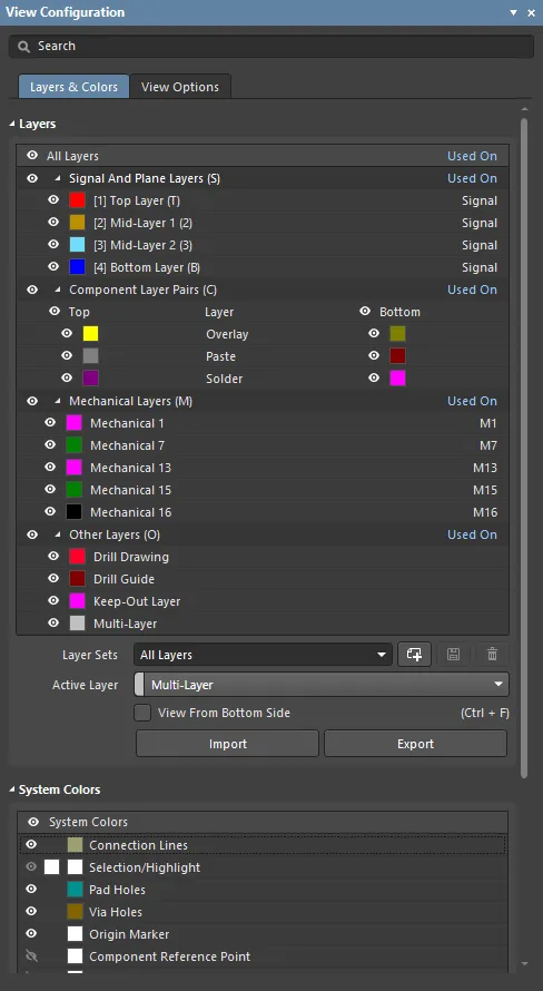
適切な場合、各グループには可視性アイコン ( ) も含まれています。例えば、上の画像では:
-
Component Layer Pairs (C) の左に可視性アイコンがあります。これをクリックすると、すべてのコンポーネントレイヤーの表示/非表示を切り替えることができます。
-
Top の文字の左に可視性アイコンがあります。これをクリックすると、すべての上面コンポーネントレイヤーを表示/非表示にすることができます。Bottom 側のレイヤーも同様に表示/非表示を切り替えることができます。
キーボードからの可視性の制御
多忙なPCB設計では、設計プロセス中にレイヤーが頻繁にオン/オフ切り替えられます。これを支援するために、次の方法でキーストロークを使用してレイヤーの可視性を変更できます:
-
L ショートカットキーを押して、View ConfigurationパネルのLayers & Colorsタブを表示/アクティブにします。パネルのタイトルバーが色付きになり、ソフトウェア内のアクティブな要素であることを示します。
-
レイヤーやレイヤーのセットの右側に丸括弧で囲まれた文字や数字があることに注意してください。例えば、Component Layer Pairs (C)、[1] Top (T) などです。丸括弧内の文字/数字はキーボードショートカットキーです。例として、L ショートカットを押してパネルをアクティブにし、次に T ショートカットを押してトップ信号レイヤーの表示を切り替えます。
-
レイヤーのセットにアクセスした場合は、Spacebarを押してそのセット内のすべてのレイヤーの表示を切り替えます。
-
レイヤーにアクセスした場合、その表示がすぐに切り替わり、その後はSpacebarを使用して再度切り替えることができます。
-
上または下矢印キーを押してリスト内を上下に移動し、例えば特定の機械レイヤーやコンポーネントレイヤーのペアにアクセスします。その後、Spacebarを使用してそのレイヤー/レイヤーペアの表示を切り替えることができます。
-
四角括弧内の数字は、レイヤースタック内でその信号またはプレーンレイヤーがどの物理的な銅レイヤーにあるかを示します。例えば、[6] Bottom (B)という文字列では、[6]はこれがレイヤースタックの6番目の銅レイヤーであることを示し、Bottomはこのレイヤーにレイヤースタックマネージャーで割り当てられたユーザー定義の名前であり、(B)はそのレイヤーの表示を切り替えるショートカットキーです。
-
信号レイヤーとプレーンレイヤーのショートカットキーは(9)で止まります。これはキーボード上で利用可能な最後の数字キーです。
シングルレイヤーモード表示でレイヤーを常に表示する
シングルレイヤーモード表示にレイヤーを含めるには、表示したいレイヤーに関連付けられた目のアイコンをCtrl+クリックします。そうすると、そのレイヤーがシングルレイヤーモード表示に追加され、目のアイコンの後ろに四角が表示されます( )。これはそのレイヤーがシングルレイヤーモードで常に表示されることを示します。
レイヤー&色タブ
レイヤー

パネルのLayers and ColorsタブのLayersセクション
-
Signal and Plane Layers – 色ボタンをクリックして、前述の Displaying or Hiding a Layerセクションで説明されているように、そのレイヤーの色を変更します。表示アイコン(  )をクリックして、個々の信号層またはプレーン層の表示を切り替えます。信号層とプレーン層は、Pad-Via Layer Editorダイアログで追加、命名、削除されます。
-
Component Layer Pairs – これらのレイヤーはペアになっており、ボードの上側から下側にコンポーネントが反転されるとき(コンポーネントが移動されている間のLショートカット)、ソフトウェアは上側レイヤーの内容をそれらのペアの下側レイヤーに反転させることができます。ユーザー定義のコンポーネントレイヤーペアは、機械レイヤーを使用して定義できます。
-
Mechanical Layers – これらは一般的な目的の描画レイヤーです。これらのレイヤーもペアにすることができ、ペアになった場合、コンポーネントレイヤーペアになります。コンポーネントレイヤーペアは、例えば、接着ドットや3Dコンポーネントボディなど、特別な目的の役割に使用されます。機械レイヤーの名前を変更するには、右クリックしてコンテキストメニューからEdit Layerダイアログを開きます。
-
Other Layers – これらはシステム管理されるレイヤーで、例えば、マルチレイヤーに配置されたオブジェクトは自動的にすべての信号層に表示され、キープアウト層に配置されたオブジェクトはすべての信号層においてクリア保持境界として機能します。
-
Layers Set – ドロップダウンから既存のレイヤーセットを選択します。レイヤーセットを作成、保存、削除するために以下のボタンが使用されます:
-

 – 新しいレイヤーセットを作成するためにクリックします。セットはドロップダウンにMy Layersとして表示されます。追加される各レイヤーセットは番号付けされます。
-

 – 現在選択されているレイヤーセットを編集したときに保存するためにクリックします。レイヤーセットの作成と名前変更には保存アクションは必要ありませんが、有効なレイヤーの構成を変更する場合、自分のレイヤーセットを含め、保存アクションが必要です。
-

 – 現在選択されているレイヤーセットを削除するためにクリックします。
-
Active Layers – ドロップダウンを使用して、PCB上のさまざまなActive Layersを個別に表示します。
-
View From Bottom Side – このボックスをチェックして、レイヤーセットを下側から表示します。
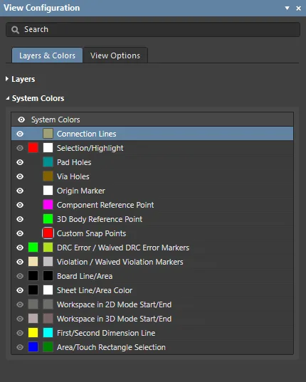
システムカラー

パネルのLayers and ColorsタブのSystem Colorsセクション
表示オプションタブ
一般設定
 General Settingsは2Dモードと3Dモードを切り替えます。マウスをホバーすると違いが表示されます。