
Altium MCAD CoDesigner
ECADとMCADの溝を埋める

あなたが手にしている電子製品は、数多くの独立した設計の融合によって成り立っています。まず手にしている筐体があり、その内部には1枚以上の電子回路基板があり、基板上にはソフトウェアを実行するマイクロプロセッサが搭載されていることも少なくありません。さらに、特殊なセンシングや信号伝送を行うための専用回路ブロックや、高速信号処理を実装するためのプログラマブルハードウェアが含まれる場合もあります。
これらの独立した設計—機械筐体、電子回路、プリント基板、マイクロプロセッサのコード、プログラマブルハードウェア—はそれぞれ固有の設計パラダイムを持ち、各設計はそれぞれの設計エディタで作り込まれます。
長年にわたり、これらの独自の設計領域はより密接に結び付くようになってきました。この密接な連携は、最終製品のあらゆる要素が正しく相互接続されることを保証し、私たちが日常的に使う携帯電話、ノートPC、電気自動車といった、使いやすく馴染みのある製品を実現するうえで不可欠です。
ECADとMCADの分断は、こうした設計領域の中で最後に橋渡しされるべきものです。中間ファイル形式に保存して橋渡しする方法でも動作はしますが、エラーが起きやすい、機能が限定される、調整・管理が難しいといった理由から、次第に不十分になってきています。
必要なのは、さまざまな機械設計パッケージへ設計変更を直接伝達できる3D PCB設計エディタです。Altiumの技術であるAltium MCAD CoDesignerは、ECADとMCADの設計領域を統合することで、この課題を解決しています。
 検索機能
検索機能PCBエディタにおける3D設計機能を理解する
 CoDesignerを使って基板設計を機械設計者とやり取りする場合、AltiumのPCBエディタで利用できる3D設計機能を把握しておくとよいでしょう。部品の3Dモデルを作成/インポートできるだけでなく、製品筐体をインポートして3Dクリアランスチェックを行うこともできます(カーソルを画像の上に置いてください)。
リジッドフレックス設計では、PCBエディタ上で基板を対話的に折り曲げることができ、最終状態で折り畳まれた基板のクリアランスチェックに最適です。
また、使用しているMCADソフトウェアがまだCoDesignerでサポートされていない場合でも、ECAD側の基板をSTEPまたはParasolid形式でエクスポートし、MCADソフトウェアに読み込める状態にできます。
► 詳細はこちら:Altium DesignerでPCBをレイアウトする
Altium CoDesignerによるECAD-MCADの直接連携設計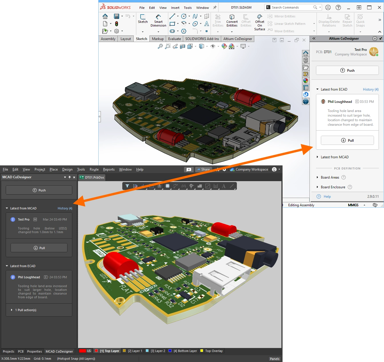
電子設計領域と機械設計領域をまたいで作業することには、固有の課題があります。複数の不規則形状のプリント基板を収める小型で複雑な筐体—こうした製品を成功裏に設計するには、ECAD設計者とMCAD設計者が、それぞれの設計領域間で設計変更をスムーズに往復させられる必要があります。
異なる設計ソフトウェア間で複雑かつ詳細な設計変更を受け渡すことは、単に別形式でデータを保存できるというだけでは不十分です。電子設計チームと機械設計チームは独立して作業しており、設計プロセスの任意の時点で、必要な変更だけを選択的に転送できる必要があります。
Altium CoDesignerはこれをサポートし、ECADからMCADへの直接的なコデザイン(CoDesign)を実現します。
► 詳細はこちら:Altium MCAD CoDesignerのインストールと設定
ECADとMCADの設計コンポーネントをリンクする
 各MCADパッケージは設計オブジェクトを独自の方法で表現・保存しており、CoDesignerはそれらすべてに対して読み書きできなければなりません。Altium CoDesignerの標準的なアプローチは、標準のParasolid形式の3Dモデルとしてコンポーネントを相互に受け渡すことで、ECADとMCADの両領域で機械的に正確な設計を保証します。
しかし、コンポーネントは物理的な外形だけではありません。たとえばPCB領域では、シルクやペーストの詳細、回路図シンボルへのリンク、さらにサプライチェーンと結び付くパラメトリック情報も保持します。理想的には、ECAD設計者とMCAD設計者がそれぞれ自分のライブラリからネイティブの設計コンポーネントを配置し、それらのネイティブコンポーネント同士をリンクできることです。CoDesignerは、共有のAltium 365 Workspaceを通じてこのリンクをサポートします。
► 詳細はこちら:ECADとMCADの設計コンポーネントをリンクする
 リジッドフレックス基板を同期する
量産に持ち込むうえで最も難しいプリント基板設計の一つが、リジッドフレックス設計です。リジッドフレックス回路の設計は、製品組み立て時に筐体内へ組み込み・折り畳めるように基板を設計する必要があるため、強い電気・機械の協調(エレクトロメカニカル)プロセスになります。これまで、この厳しい電気・機械の設計課題は、機械的なモックアップ(いわゆる紙人形の切り抜き)を作ることで解決されてきました。
Altium CoDesignはこの課題の解決を支援し、折り畳まれたリジッドフレックス設計をECADとMCADの間で転送できるようにします。
► 詳細はこちら:リジッドフレックス基板を同期する
マルチボードアセンブリを同期する
 電子機器は、複数の回路基板をアセンブリとして構成し、機械筐体内に巧みに成形・配置することで機能製品として成立することがよくあります。PCB自体はECADで設計しますが、各基板の形状を定義し、完成したPCBを筐体内に配置する作業は、MCADで行うのが最適です。
そのためには、個々の基板と、(筐体を含む)PCBアセンブリ全体を、ECADとMCADの間で双方向に同期できる必要があります。
► 詳細はこちら:マルチボードアセンブリを同期する
 ハーネス設計プロジェクトを同期する
マルチボード製品では、ハーネスを使ってPCB同士を接続するほか、ユーザーが操作する各種ボタン、ディスプレイ、コントロール類への配線も行います。
PTC Creo上のAltium MCAD CoDesignerは現在、ECADとMCAD間でハーネス設計を同期する機能をサポートしており、コネクタ、スプライス、接続性、トポロジーをECADからMCADへ転送し、ハーネス要素の物理長をMCADからECADへ戻します。
► 詳細はこちら:ハーネス設計プロジェクトを同期する
ECAD-MCADビデオチュートリアル

動画で学びたいですか? それなら、拡充中のECAD-MCADビデオチュートリアル集をご覧ください。各動画では、たとえば「MCADでPCB形状を作る」や「設計交換中にMCAD制約を維持する」といった、特定の設計課題を解決する方法を手早く概説します。
► 視聴する:ECAD-MCAD Video Tutorials
次は何をしますか?
Altiumソフトウェアが初めての場合は、concept-to-completion tutorialから始めるとよいでしょう。9個の部品からなるシンプルな回路を題材に、空の回路図シートから開始し、PCBの完成と、基板製造に必要なファイル一式の作成まで進めます。Altiumの設計技術と同様に、各エディタは学習しやすく、作業しやすいように設計されています。状況に応じた右クリックメニューが広く使われており、コンテキストヘルプ(F1)やコマンド内ショートカット一覧(Shift+F1)も、あらゆる場所で利用できます。
それ以外にも、次の記事をご覧ください:
 AI で翻訳