
Design Data Comparisons
The Altium 365 Workspace project view provides design data comparison features that allow you to compare data changes that have occurred between different project releases and/or commits. Particularly valuable for performing final checks prior to sending your product data to the manufacturing side, the features allow you to determine exactly what changes have occurred in your Gerber, Schematic. PCB, and BOM data between release/commit events.
Gerber Comparison
Making a final check of your fabricated board data prior to sending out to the manufacturer is always a good thing. The Gerber comparison feature facilitates just that, with the ability to quickly check to ensure no differences in your fabrication output between released iterations of your design project. It provides a purely graphical, layer-by-layer comparison, highlighting areas with changes using a bounding box and a number.
Gerber Comparison Access
The Gerber comparison feature can be accessed by:
-
Clicking the
 button associated with a specific release of a project in the Releases view of the detailed management page for that project. Choose the Gerber to option and which other release's fabrication data to compare against, or compare against an uploaded file set.

-
Clicking the button at the top-right of the Manufacturing Portal browser tab, when viewing a specific release package for a design project. Choose the Gerber to option and which other release's fabrication data to compare against, or compare against an uploaded file set.

-
Clicking the
 control at the top-right of a Project Released event tile in the History view of the detailed management page for the project, and choosing the Gerber to option. Compare against the previous release's fabrication data, select from all possible releases, or compare against an uploaded file set.

Comparing with a File Set
You have the ability to compare the Gerber data in a release package against an uploaded Gerber file set. This enables you to compare against, for example, Gerber data that has been generated locally from the latest live design, prior to making the next formal release of the project to your Workspace.
As mentioned previously in the Access section, this comparison is performed by choosing the Gerber to » Files entry in the applicable menu. The Compare Gerber window will appear. Either click on an existing zip of Gerber files, or upload a fresh set.
 The Gerber Comparison feature supports the comparison of data in a release package against a locally generated file set.
With the existing Gerber file set chosen, or uploaded, the result of the comparison will be presented momentarily – see the next section.
Gerber Comparison Result
Once the comparison release or uploaded file set has been chosen, the results of the comparison are presented in the Gerber Compare view, which opens in a separate browser tab.


Browsing Controls
Browsing controls for the main viewing area are as follows:
- Mouse wheel forward/backward to zoom in/out.
- Click & hold (or right-click & hold), then drag to pan document.
Taking Measurements
You can freely measure between any two points within the view, without any snapping guidance whatsoever. To do so click the ![]() button. The Measurements pane opens, the cursor changes to a cross-hair, and you will enter measurement mode.
button. The Measurements pane opens, the cursor changes to a cross-hair, and you will enter measurement mode.
Measurement is performed as follows:
- Position the cursor to where you wish to start measuring (Point 1) and click. The point is marked using a small white cross.
- Move the cursor to the required end point (Point 2) and click again. As you move the cursor, a measuring line is displayed as an aide, showing the current XY distance (from Point 1 to the end of the line).
- The Measurements pane reports the XY distance measured, the X (horizontal) distance, and the Y (vertical) distance.
-
Continue measuring the distance between other points, or click the
 button again (or Esc) to exit measurement mode.
 Example measurement taken on the Compare view of the Gerber data.
Schematic Comparison
Along with the comparison of Gerber data (see above), the project view also provides the ability to compare project schematic documents in a simple interactive interface. This offers a quick and convenient way to see only what changes have occurred between schematic iterations.
The Schematic Comparison feature presents differences graphically and as parametric data, which are listed in an associated Compare pane that allows cross-probing to the related schematic object(s). A comparison can be invoked between project Releases, project Commits, or between project Commits and Releases (available from the History view).
Schematic Comparison Access
The Schematic comparison feature can be accessed by:
-
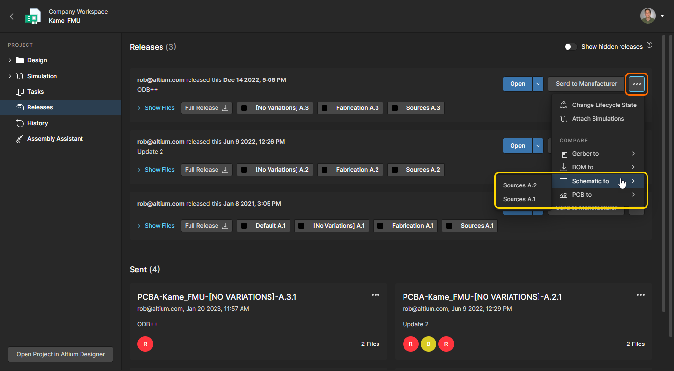
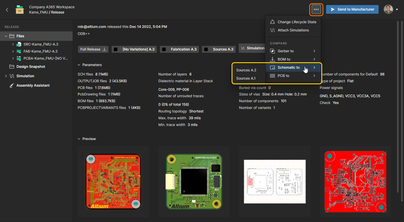
Choosing the Schematic to option from the
button menu in the Releases view, and then which other release's design source data to compare against. Or by choosing the same option in the Manufacturing Portal browser tab when viewing a specific project release package, and then which other release's source data to compare against.
-
Choosing the Schematic to option from the control at the top-right of a Commit or Release event tile in the History view, and then another Commit/Release event to compare against. Schematic data from the last release/commit can be selected (Previous Release or Previous Commit), or the data from any Commit/Release event by choosing the Select Commit or Release option – select the target comparison event by clicking on its tile.
 Open Schematic Compare from the History view in Altium Designer or the Altium 365 browser interface.
Schematic Comparison Result
When the comparison Commit/Release pair has been selected, the results of that comparison are opened as the Schematic differences view in a new browser tab. The first schematic in the source documents is presented by default, and the logical differences found (changed Component and Net data) for all schematics are presented as a selectable list in the associated Differences pane. Note that purely graphical changes, such as a moved component, are not included at this time.

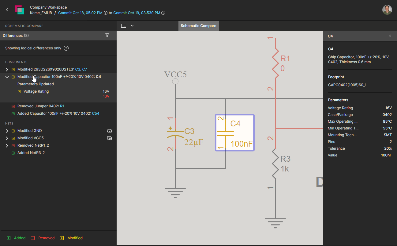

Select a listed element in the Compare pane to expose any available change details and cross probe to its schematic graphic. Each element in the list has an associated icon indicating its general change status – red: removed, green: added, yellow/orange: modified. The same coding is used in the cross-probed schematic graphics.
The pane's differences list is grouped by Components and Nets:
-
Components – Each entry includes the names of affected components, and when selected, expands a list of any changed component parameters (highlighted in red) and unchanged parameters (green). Select the RefDes of a component included in the entry (highlighted in blue) to cross probe to its schematic graphic.
-
Nets – Each entry includes the names of any components affected by a net modification, or conversely, the name of components that caused a net modification. Select a Net entry in the pane to cross probe to the entire net on the active schematic, or a RefDes included in the entry to focus on that net component.

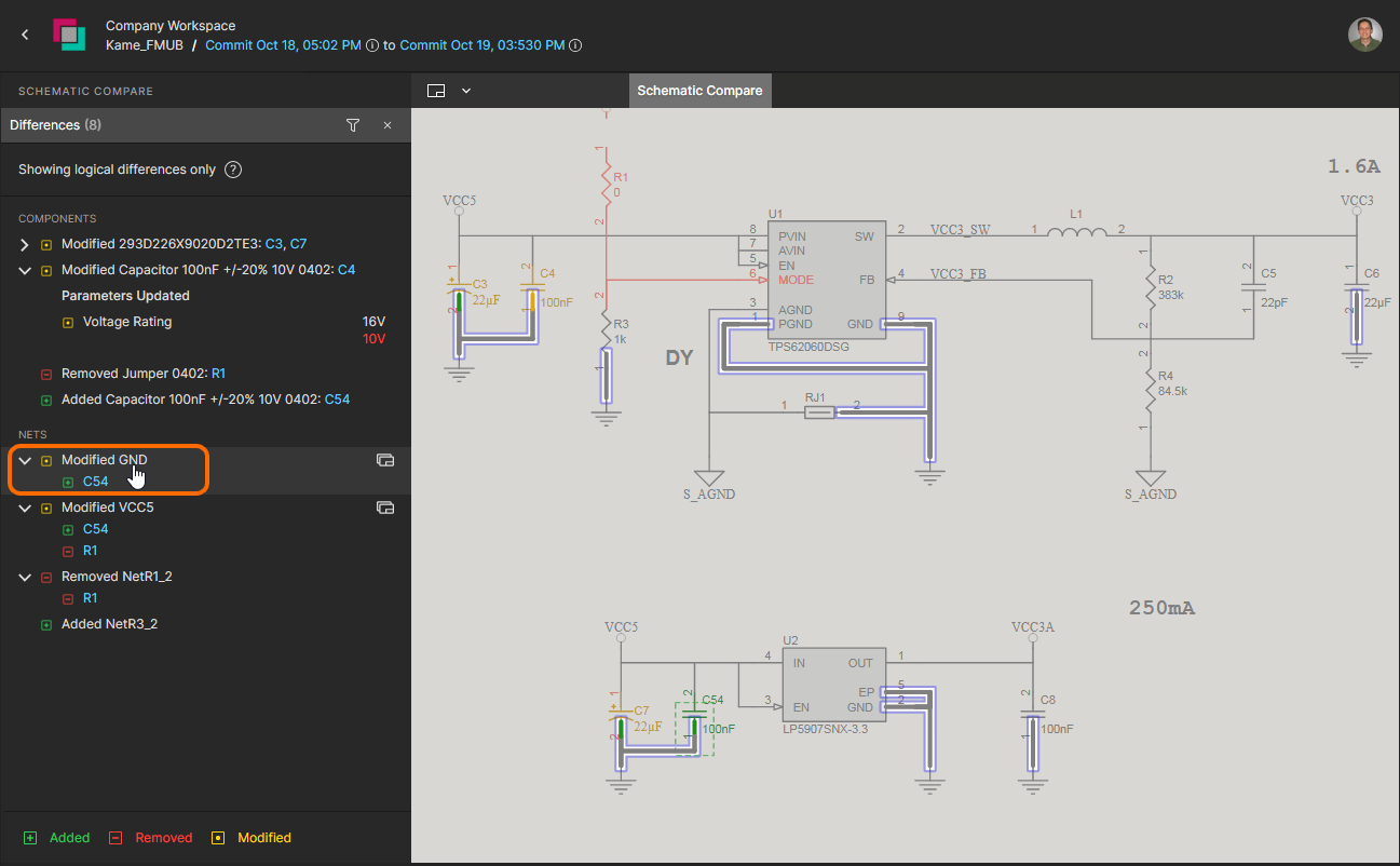
A ![]() icon associated with a Net entry in the Compare pane indicates the presence of that net in other schematic documents. Select the icon to access a drop-down list of those schematic documents, where each document affected by the net change is indicated by yellow highlighting. Choose a schematic document from the menu to cross probe to the net on that schematic, which is highlighted accordingly.
icon associated with a Net entry in the Compare pane indicates the presence of that net in other schematic documents. Select the icon to access a drop-down list of those schematic documents, where each document affected by the net change is indicated by yellow highlighting. Choose a schematic document from the menu to cross probe to the net on that schematic, which is highlighted accordingly.
 The entry for a modified Net includes a link to other schematic documents that also include the Net.
PCB Comparison
As a companion to Schematic compare, the Workspace project view offers a PCB comparison feature that detects and shows changes to the board design that have occurred between project commits and/or release iterations.
The PCB Compare feature provides a highly visual, Interactive interface for viewing PCB layout differences and the associated comparison data, with reactive cross-probing available between listed data differences and their associated graphics elements. A PCB comparison can be invoked between project Releases, project Commits, or between project Commits and Releases (available from the History view).
PCB Comparison Access
The PCB comparison feature can be accessed by:
-
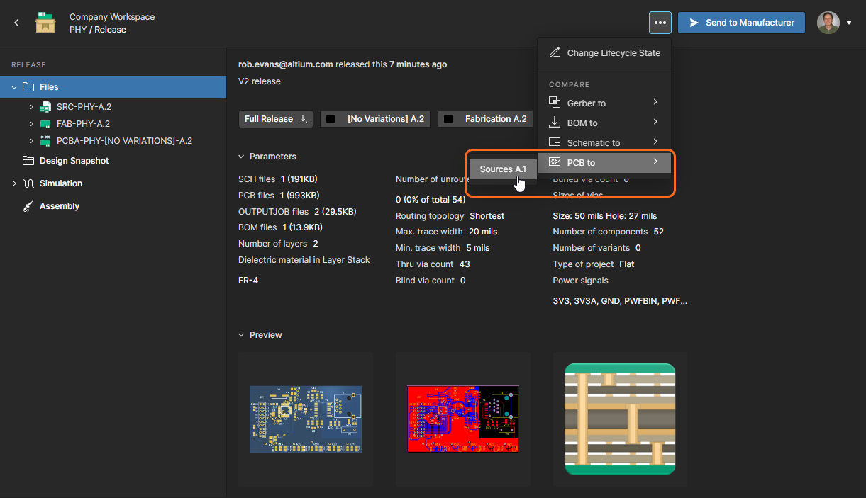
Choosing the PCB to option from a release entry's
button menu in the Releases view, and then which other release's design source data to compare against. Or by choosing the same option in the Manufacturing Portal when viewing a specific project release package, and then which other release's source data to compare against.

-
Choosing the PCB to option from the
control at the top-right of a Commit or Release event tile in the History view, and then another Commit/Release event to compare against. Schematic data from the last release/commit can be selected (Previous Release or Previous Commit), or the data from any Commit/Release event by choosing the Select Commit or Release option – select the target comparison event by clicking on its tile.

PCB Comparison Result
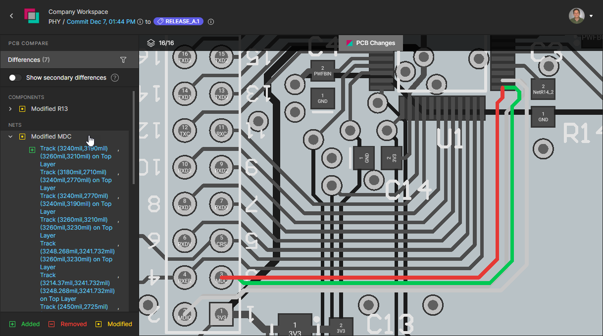
When the comparison Commit/Release pair has been selected, the results of that comparison are opened as the PCB Changes view in a new browser tab. The view presents the PCB compare engine results as a graphical representation of the board with unchanged elements shown in monochrome, and modified net-connected elements highlighted in green (added), red (removed) and yellow (modified). Note that modified Polygons are dimmed to enhance the clarity of board Net elements.
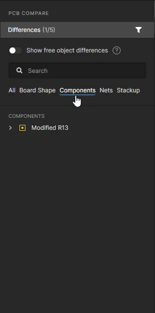
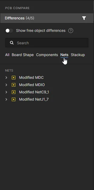
The Differences pane on the left lists the detected differences within groups of object types – Components, Nets, etc. When a difference entry is selected in the pane it expands to list the sub elements that make up that detected difference. The board view will automatically pan and zoom to show the area of change, where objects that have been removed are shown in red and any added objects are colored green. Click the selected difference entry again to deselect it and restore PCB view to its initial overview mode.

Note that clicking on a difference entry name will toggle its selection state and matching board view. Use the associated expand/contract control on the left of an entry's name to toggle its sub-element list view.
Navigate through the differences by clicking on each entry, which will automatically expand the sub-list of its changed elements.
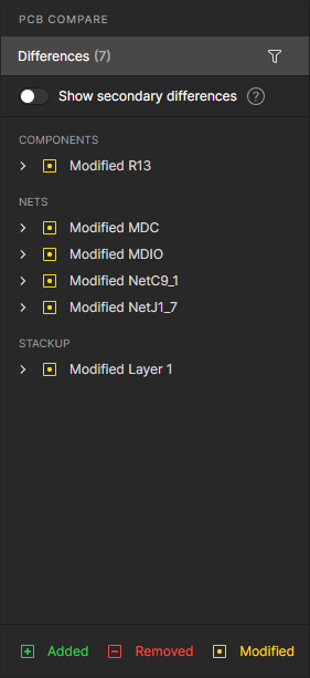
The below example shows how the location and associated routing for component R13 has changed between subsequent Commits/Release events, and how that difference is presented in the corresponding PCB Compare view. The differences, as listed in the Differences pane, include modification entries for R13 and its two associated Nets (NetC9_1 and NetJ1_7).
 Added net-based elements are shown in green, removed elements in red, and modified elements in yellow.

The differences can be examined in detail by selecting individual change elements within the expanded sub-list under each difference entry. Components sub-entries include parameter and positional changes (previous position shown in red), and the listed Net changes are sectioned into added/new sub-net tracks (![]() ) and removed/replaced tracks (
) and removed/replaced tracks (![]() ). When selected in the sub-list, the tracks are visually highlighted in the board view as red and green, respectively. Note that a Net entry also includes changes to the calculated
). When selected in the sub-list, the tracks are visually highlighted in the board view as red and green, respectively. Note that a Net entry also includes changes to the calculated Routed Length and Delay (previous figure shown in red).
Each sub-element in a differences entry includes details of the specific change, and when selected will highlight that element in the PCB view.
The Differences pane Show secondary differences option is disabled by default to reduce clutter caused by changes where the Net objects (components, tracks, Vias, etc) have not been altered. These include:
-
Free Object differences: Changes to objects not connected to a Net or on non-copper layers.
-
Nets with only a Routed Length difference: Changes in a Net's length (but not its Delay) which is typically caused by a Layer Stack update such a modified layer Thickness (and therefore an altered Via barrel length).

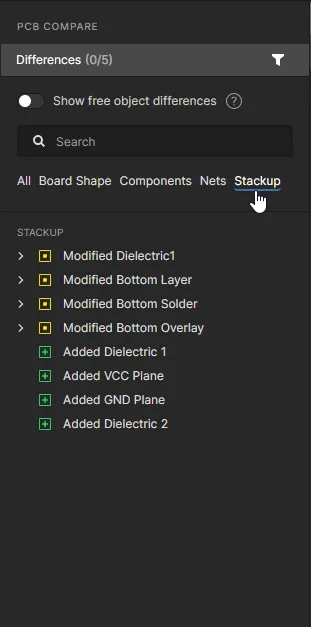
Controlling Layer Visibility
Control over the view and layer visibility for the PCB Compare view is performed through the Layers pane, opened from the ![]() control above the board view. The control's numeric text will dynamically change to indicate the current number of enabled layers compared to the total available layers.
control above the board view. The control's numeric text will dynamically change to indicate the current number of enabled layers compared to the total available layers.
Use the ![]() icon associated with each layer entry to toggle its visibility in the board view. The pane's layer entries are grouped in functional categories (
icon associated with each layer entry to toggle its visibility in the board view. The pane's layer entries are grouped in functional categories (Copper, Solder Mask, etc), where the visibility of each complete category can be toggled with its associated ![]() icon. Re-enable the visibility of all layers using the
icon. Re-enable the visibility of all layers using the ![]() icon at the top.
icon at the top.
Toggle the visibility of individual layers or collected groups of layers.
Similarly, use the pane's Only option associated with each layer and layer group to enable viewing of only that layer/group (all others are disabled). Re-enable the visibility of all layers using the ![]() icon at the top. Use the Top View and Bottom View options to flip the board view, while maintaining the current layer and differences selections.
icon at the top. Use the Top View and Bottom View options to flip the board view, while maintaining the current layer and differences selections.
Select the individual view of any layer – effectively single layer mode – or flip the view between the Top and Bottom board views.
Filter Differences
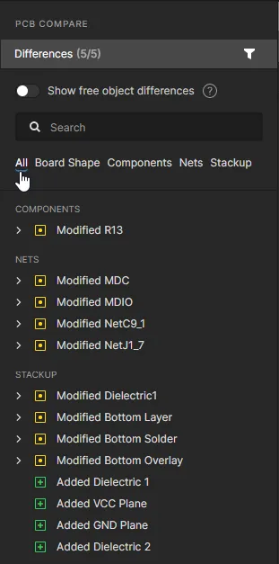
Select the Differences pane's ![]() option to filter the type of differences that are included in the listing. Reducing the list to specific difference categories will assist in navigating through the entries by reducing their number and by tailoring the results to only the difference types of interest.
option to filter the type of differences that are included in the listing. Reducing the list to specific difference categories will assist in navigating through the entries by reducing their number and by tailoring the results to only the difference types of interest.
BOM Comparison
The project view also provides a quick BOM Comparison feature to detect and show any design component data changes that have occurred between commit and/or release iterations. The differences are reported in text (CSV) form and made available as a local download.
BOM Comparison Access
The BOM Comparison feature can be accessed by:
-
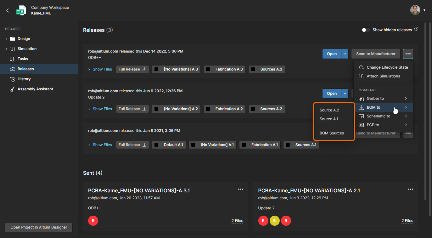
Choosing the BOM to option from the
button menu in the Releases view, and then which other release's data to compare against. Or by choosing the same option in the Manufacturing Portal browser tab when viewing a specific project release package, and then which other release's data to compare against.

- Choosing the BOM to option from the control at the top-right of a Release or Commit event tile in the History view, and then another Commit/Release event to compare against. BOM data from the previous Commit or Release can be selected (Previous <Commit/Release>), or the data from any Commit/Release event by choosing the Select Commit or Release option – select the target comparison event by clicking on its tile.
 Open Schematic Compare from the History view in Altium Designer or the Altium 365 browser interface.
BOM Comparison Result
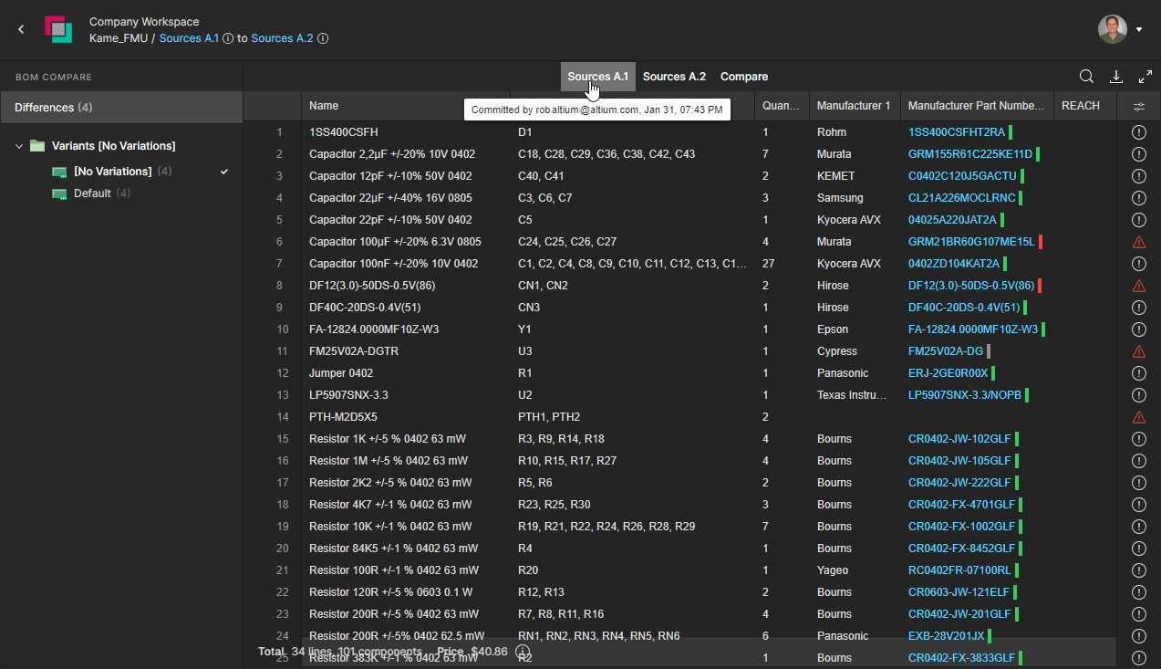
The system will compare the BOM data between the specified project Releases or Commits, and then open the results of that comparison as the BOM differences view in a new browser tab. This view is populated with a list of color-coded entries that represent BOM items that have changed between the specified BOM events. Additional information and control is provided by the BOM Compare pane on the left, which allows you to choose an alternative design Variant, select/deselect the inclusion of component change categories (Added, Removed, Modified), and view component modification details.
 The initial BOM Compare view includes entries representing the differences between the source and target BOM documents.
The BOM Comparison interface offered a range of features for accessing differences information. These include:
- Hover the cursor over the icon associated with a BOM compare entry to see a summary of the changes that have occurred.

-
Use the Column Settings menu (
 ) to enable or disable the inclusion of specific component parameter data columns.

- Select a Modified Components entry in the BOM Compare pane to view a detailed list of changes for that BOM component entry. These details also will include any differences in Manufacturer and Supplier information – see example.

BOM entries that have not changed can be included in the listing by checking the Not Modified option in the Compare pane, or to see the source BOM listings that have been specified for the comparison, select their individual tabs available at the top of the comparison listing.


Invoked from the download option (![]() ), the comparison engine will also generate a summary of any updates in a standard CSV format. The BOM comparison summary is generated for the currently selected Variant of the design, and includes details of BOM data that has changed – been updated – between the specified project releases/commits.
), the comparison engine will also generate a summary of any updates in a standard CSV format. The BOM comparison summary is generated for the currently selected Variant of the design, and includes details of BOM data that has changed – been updated – between the specified project releases/commits.
 The downloaded BOM comparison CSV files show data that has been updated between the project releases specified when invoking the compare feature.