
Defining, Scoping & Managing PCB Design Rules
Altium Essentials: PCB Design Rules Creation
This content is part of the official Altium Professional Training Program. For full courses, materials and certification, visit Altium Training.
In Altium Designer, design requirements are applied using an elegant – target these objects and apply those requirements – approach. It does this using the concept of rules, or constraints, to define the requirements of a design. Collectively known as the design rules or design constraints, they collectively form an instruction set for the PCB editor to follow. The design constraints cover every aspect of the design – from routing widths, to clearances, to power plane connection styles, to routing via styles, and so on.
Many of these design requirements can be monitored in real-time by the online Design Rule Checker (DRC), and you can also run a batch test at any time to generate a DRC report.
Fundamentals of the PCB Rules System
The rules system built into the software's PCB editor has several fundamental features that set it apart from most other design rule systems employed by other PCB editing environments:
-
Rules are separate from the objects – a rule is not added as an attribute of an object, but rather, the rule is scoped so that it targets that object. This allows rules to be applied to multiple objects, and easily modified, duplicated or applied to different objects.
-
Rules are targeted (scoped) by writing a query – instead of using a set of fixed, predefined rule scopes, a flexible query system is used to define the objects to which a rule is applied. This gives precise control over the target of each and every design rule.
-
Rules for any design situation – multiple rules of the same type can be defined and targeted to different sets of objects, allowing complete control over the definition of board constraints. For example, different width rules can be defined to route nets at different widths on different layers.
-
Each rule has a priority – any design object can be targeted by multiple rules of the same type, catering for general and more specific situations. When there are potential rule contentions, the rule priority is used to find the applicable rule.
-
There are two types of rules – unary rules (rules that define the required behavior of the object) and binary rules (rules that define the interaction between two objects).
What Approach Do I Use for Defining the Design Constraints?
Each time you place or edit an object in the graphical design space, the PCB editor checks with the rules system to find out what constraints apply to that object – how wide it should be, how far it must be placed from adjacent objects, and so on. At the lowest level those requirements are defined as design rules (or constraints), not as attributes of the objects.
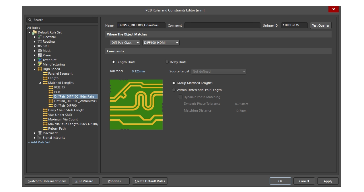
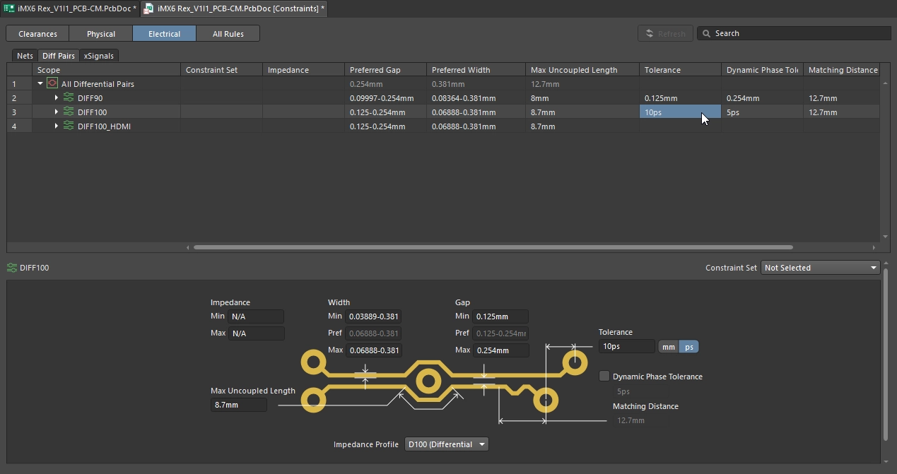
Altium Designer supports two approaches to defining the design constraints, either by working directly with the individual design rules in the PCB Rule and Constraints Editor dialog, or by configuring the constraints in the object-centric Constraint Manager.
-
The advantage of the PCB Rule and Constraints Editor approach is that it is rule-centric – focus first on the requirement, then what objects you want those requirements to apply to. Note that the design rules must be defined in the PCB editor, with limited support for defining them during schematic capture. Another advantage of the PCB Rule and Constraints Editor approach is that it supports reusable Rule Sets. Rule sets can be created, duplicated, enabled or disabled, renamed, deleted, imported, and exported, making it easier to manage rules for specific interfaces, manufacturing requirements, or unique design constraints. Rule sets are described later on this page.
-
The advantage of the Constraint Manager approach is two-fold. Firstly, it supports an object-centric approach in a spreadsheet-like editor – for this set of nets, I want to apply these requirements. Secondly, because the design constraints are stored outside of the PCB file, the Constraint Manager supports defining the design requirements as soon as you start drawing the schematic.
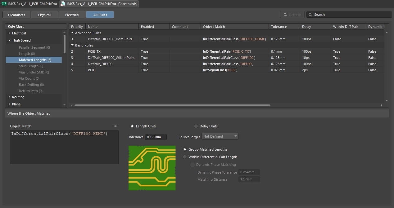
This page focuses on the underlying PCB editor rules system and how you define, scope and manage the design rules. Even if you plan to use the Constraint Manager to define and manage the design requirements, it is still important that you understand how the underlying rules system works because ultimately, the constraints you configure in the Constraint Manager are translated into design rules before they are interpreted by the underlying PCB editor rules system.
The PCB Rules and Constraint Editor
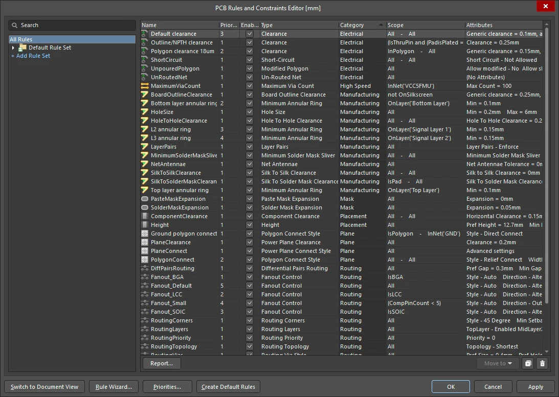
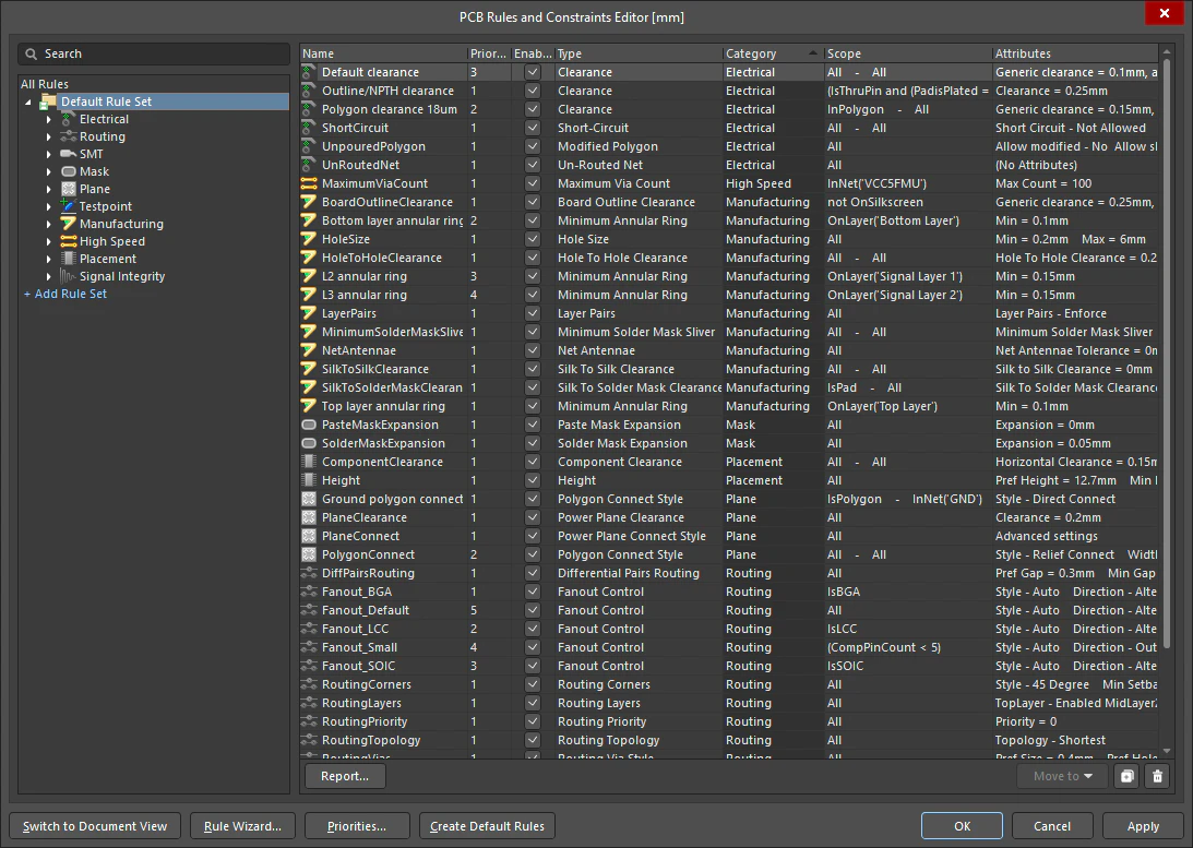
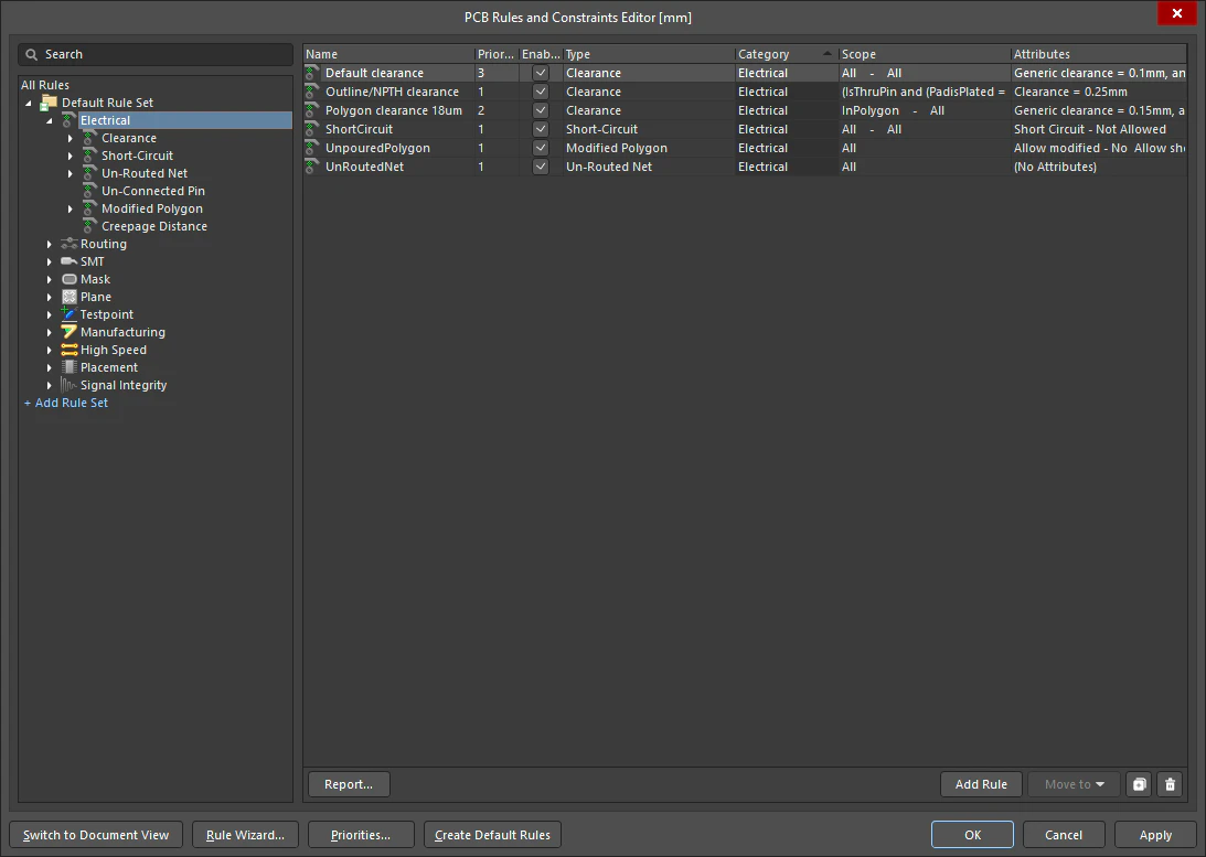
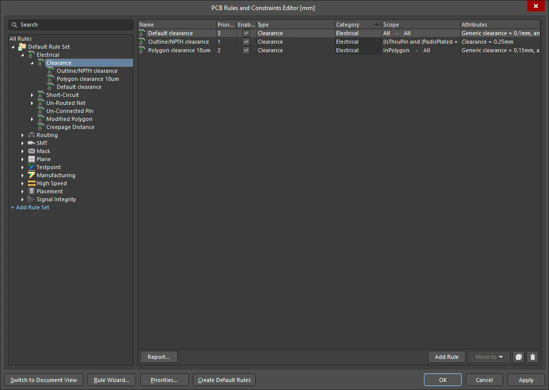
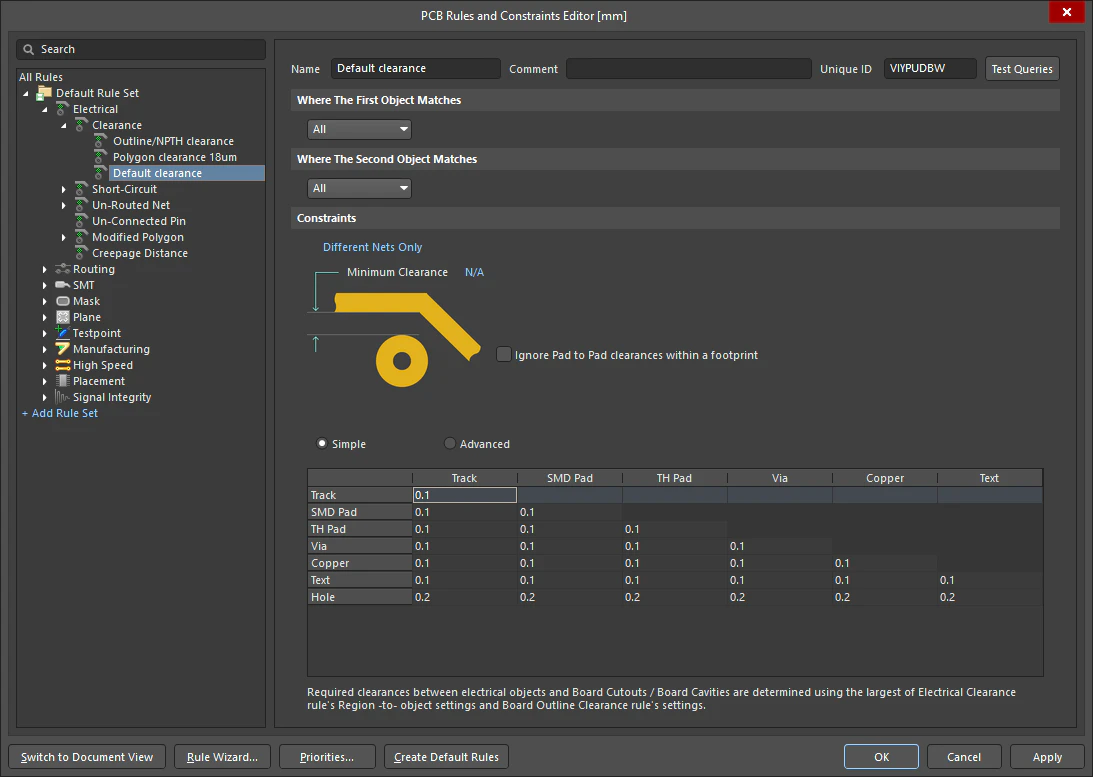
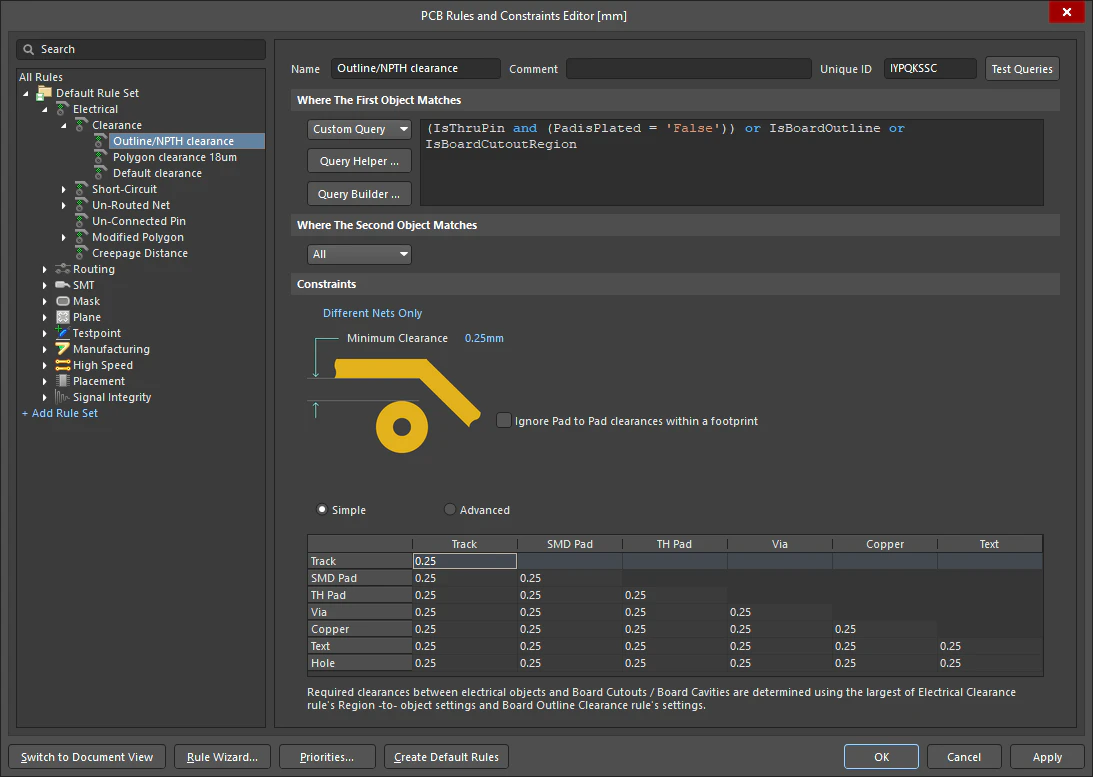
The PCB Rules and Constraints Editor dialog is accessed by choosing the Design » Rules command from the main menus. The dialog has two main sections, as described in the slides below:
PCB Rules and Constraints Editor |
|
| Tree on left of the dialog | Like the Windows File Explorer, the tree on the left displays a structured view of how the rules are organized into Types and Categories. Double-click to drill down the tree structure. Click on an icon in the structure to show the contents of that level of the structure, as described in the slides above. |
Right side of the dialog – list of rules (slides 1 to 4) |
In the list of rules on the right side of the dialog, the following columns present:
|
Right side of the dialog – selected rule (slides 5 & 6) |
When a specific rule is selected in the tree on the left (or its entry is double-clicked on in a summary list) the settings of that rule appear on the right side of the dialog, with the following options:
|
| Search | The Search field at the top left of the dialog searches the user-defined rule Name and Comment fields, and the text on the dialog face for the individual rule settings. The search performs an OR function when multiple words are entered. |
| Switch to Document View | Clicking this button switches to display the rules using a document-style presentation. This is a deprecated feature that is no longer under development. |
| Rule Wizard | The Rule Wizard can be used to walk through the process of creating a new design rule. The button will be unavailable if there are modifications to existing rules that have not yet been saved. More about the Rule Wizard. |
| Priority | When there are multiple rules of the same Type defined, for example multiple Width rules, each rule is assigned a priority. When a new rule is added it is automatically given the highest priority, when an existing rule is duplicated it is given the priority just below the rule it was duplicated from. The priority is only used when there are multiple rules that apply to the objects targeted by the rules' scopes. More about configuring the rule priorities. |
| Create Default Rules | There are a number of rules that the PCB editor requires to be present for a design rule check to be performed, each rule definition indicates if a default rule of that type is required. This button can be used to restore any required rules that have been accidently deleted. If a default rule has been modified, clicking this button will not reset it or replace it. |
| Units displayed in the dialog | Press the Ctrl+Q shortcut to toggle the dialog units between imperial and metric. Note that this does not change the current setting of the board units. |
Creating a New Rule
To add a new design rule from within the PCB Rules and Constraints Editor dialog, navigate to the required rule set within the left-hand tree, navigate to and select the required rule type, and then click the  button below the rule summary list, or right-click over the required rule type then select Add Rule from the context menu.
The new rule will be added to the folder tree and will also appear in the summary list for that rule type. The rule name will appear bold to distinguish it as being new and yet to be 'applied'.

Example creation of a new PCB design rule.
Creating a New Rule |
|
| Default rules | When a new PCB document is created it includes a number of default rules, which must exist for the correct functioning of the Design Rule Check system. If a default rule is deleted, it is automatically re-created when the PCB Rules and Constraints Editor is closed. If there are design rules that you do not wish to use, the correct approach to managing these rules is to disable them. |
| Default units | Default rule values are internally defined in mils and may have values that do not suit your designs. To use your own default rules and values, you can:
|
| Disabling a default rule | To disable a rule, toggle the corresponding Enabled option for that rule in one of the summary lists on the right-hand side of the PCB Rules and Constraints Editor dialog. A disabled rule appears 'grayed-out'. More about disabling design rules. |
| Name of the new rule | When a new rule is added, it will initially be given a default name based on the specific type of rule. For example, if you add a new Clearance rule, the default name will be Clearance. If this default naming is not changed, adding another new rule of the same type will result in the same rule name with an incremented numerical suffix (i.e. Clearance_1, Clearance_2, etc.). A good approach that helps with rule management is to name the rule by the object it applies, for example Clearance-DiffPairs. |
| Priority of the new rule | When a new rule is created for a particular rule type, it is automatically given priority 1 (the highest priority). If any other rules of that type exist, their priorities will be shifted (lowered) by one, accordingly. They are then considered to be modified – even though they may not have been specifically modified at the individual scope/constraint level. All such existing rules of that type will therefore be displayed in the modified state (bold with an asterisk). More about the rule priority. |
| To edit the rule settings | To access the scope and constraint attributes for the rule, either click on the entry for the rule in the folder-tree pane or double-click on its entry in a summary list. The main editing region of the dialog will change to give access to the controls for defining the scope and constraint attributes for that rule ( ). ). |
| Use the Rule Wizard | Launch the wizard using the Design » Rule Wizard command or by clicking the Rule Wizard button at the bottom of the PCB Rules and Constraints Editor dialog. Use the pages to (
|
| Duplicate an Existing Rule | To duplicate an existing rule (
The duplicate rule will be named the same as the original, with the addition of a suffix (e.g., |
| Creating a rule from the PCB Filter panel | An excellent way to build competence in writing queries is to use the PCB Filter panel, which is purpose-built for targeting objects in the design space. Once the required query has been crafted in the panel you can click the Create Rule button ( |
| Is the rule ready? |
|
 )
) )
) button below the list.
 )
)Scoping a Design Rule
Design rules target specific objects within a design. For the PCB rules system to know for which objects a given rule applies, it needs to know the scope of that rule, that is, the extent of its application.
Scoping, or targeting the rule, is performed in the PCB Rules and Constraints Editor dialog.

Set the scope of a design rule to define its application to the design objects – this rule targets all objects in the VBAT net that are on the bottom layer.
Scoping the Rule |
|
| Targeting the rule | Scoping, or targeting the rule, is the name given to the process of define the set of objects that rule is to apply to. This is done by configuring the Where The Object Matches settings. The default scope for a new design rule is All, meaning it will be applied to all objects on the board. Using the drop-down, a simple rule scope can be quickly configured, with each choice presenting additional drop-downs to precisely target the required objects ( ). When you scope the rule using the simple scoping options, a query is still created. You can examine the query behind any of these options by switching to ). When you scope the rule using the simple scoping options, a query is still created. You can examine the query behind any of these options by switching to Custom Query in the drop-down. |
| Using a custom query | To enter a custom query, set the first Where The Object Matches drop-down to |
| Writing the query | A query is essentially an instruction to the software that defines the set of design objects to be targeted. Queries are written using query keywords, an example might be (
If this query were to be used as the scope for a Width rule, when you route the VBAT net and switch to the bottom layer, the track width would automatically change to the width specified as part of that rule's Constraints. Also, upon running a design rule check, any VBAT net routing on the bottom layer would have to have the specified width or it would be flagged as a violation. More about writing a query. |
| Unary or Binary rule | A Unary rule applies to the object(s) targeted by the rule scope, a Binary rule applies between the objects targeted by the rule scope. Depending on whether the rule is unary or binary, you will need to define one or two scopes respectively. For a unary design rule, controls will be provided to define a single rule scope. Use the options available in the Where The Object Matches region to help build the query expression, which will be presented in the region to its right. For a binary design rule, controls for Where The First Object Matches and Where The Second Object Matches will be provided to define both rule scopes. Use the available drop-downs of each to help build the query expression. Controls are the same, whether defining one or two rule scopes. |
| Changing the name of the object that a rule applies to | When changes are made to PCB component designators or polygon names, the references in design rules using custom queries are updated automatically. The queries referencing PCB component designators in design rules are changed when designators are reannotated, updated by an ECO, or manually edited on the board (
|
| The impact of a Query syntax error | If there is a syntax error with the query, the rule will be deemed invalid and will be highlighted in red in the PCB Rules and Constraints Editor dialog both in the left-hand rule tree and any summary view (rule category or rule type) in which the rule appears. A warning message will also appear if you attempt to close the dialog. A rule scope that has a syntax error can greatly slow the Online and Batch DRC analysis process. Be sure to resolve any rule scopes that are not syntactically correct. More about managing design rules. |
 )
) ).
).Writing a Custom Query
The Custom Query option enables you to write your own, perhaps more complex but also more specific query. You can type your own specific query for the rule scope directly into the query region to the right. Alternatively, two features are available to help in the creation of logical query expressions. They are the Query Builder and the Query Helper (summarized below). These can be useful when you are unsure of the syntax of a query or the keywords that are available.

Use the Custom Query option to craft a more complex query expression.
Writing a Custom Query |
|
| Writing a query | If you are conversant with the Query Language, you can enter a query expression directly in the query region. You can also paste a query expression from your favorite editor directly into the region or copy a query expression into an external editor, or even to paste the query into the second scope of a binary rule. This is especially useful if the two scopes are complex and differ only slightly. |
| The PCB Filter panel | An excellent way to build competence in writing queries is to use the PCB Filter panel, which is purpose-built for targeting objects in the design space. Checkbox options can be used to target objects and layers, with a query being built as they are enabled. This query can then be edited as required to filter out all unwanted objects, returning only those of interest. The panel also includes access to the Query Helper, Query Builder, your History of previous queries, and your current Favorites. The current Filter panel query can also be used to scope a new design rule. |
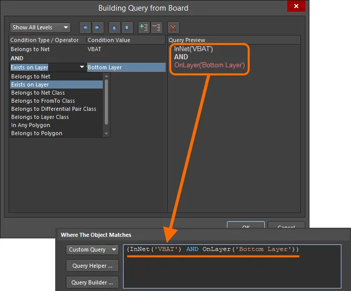
| Query Builder | The Query Builder is a guided method of constructing a query that uses sensitive condition types and values that only allow you to build using relevant 'building blocks'. When the Query Builder button is clicked the Building Query from Board dialog opens, where you can create a query for targeting specific objects in the design document by the constructing a string of conditional statements ( Each condition is made up of a Condition Type and a Condition Value. Drop-down fields for these populate with entries that are relevant to building a scope for the current rule type and values for the chosen condition type, respectively. As a condition is defined, a preview of the currently built query is shown in the right-hand section of the dialog. Conditions can be ANDed and/or ORed together, and also precedence incorporated (through the use of brackets/indenting) to refine the target set of objects. When the expression for the query has been defined as required, clicking OK will load the expression into the query region of the PCB Rules and Constraints Editor dialog. Learn more about the Query Builder. |
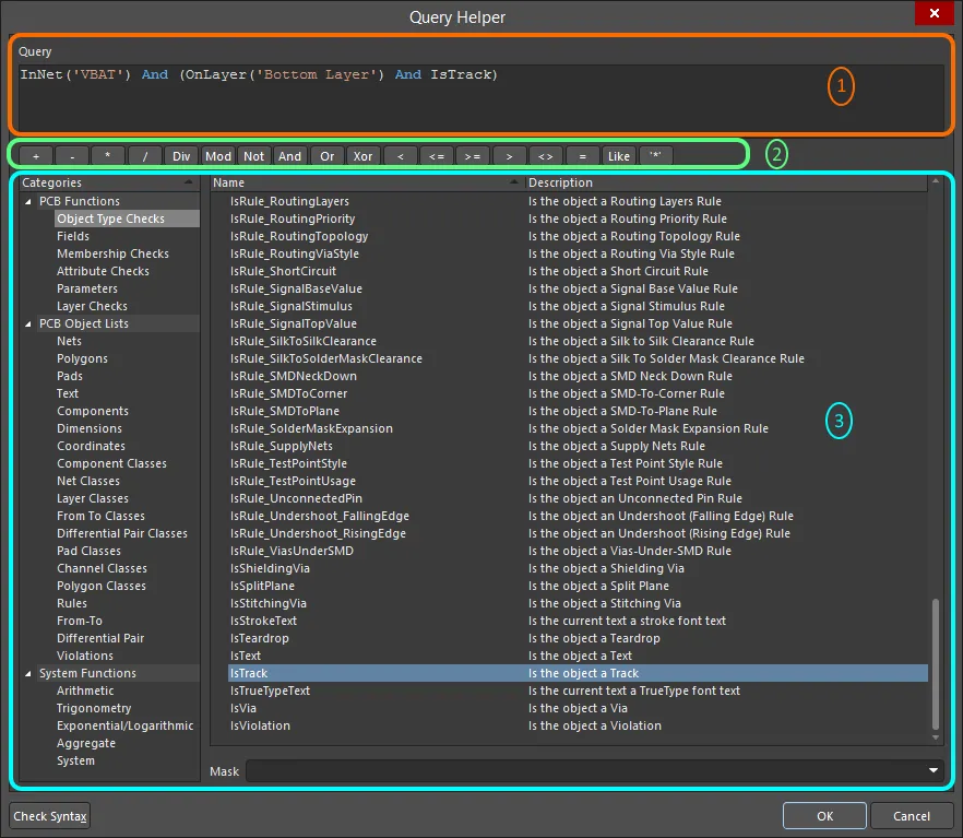
| Query Helper | For advanced query construction with full keyword specification and operator syntax, click the Query Helper button to open the Query Helper dialog (
Learn more about the Query Helper. |
| Query history | All queries written and applied in the PCB Filter panel are logged in the Expression Manager dialog, in the History tab. These can be re-used at any time, or retained as a Favorite (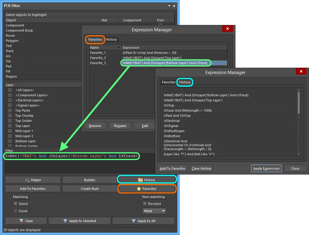 ). ). |
| Favorite queries | Any of the queries in the query history can be stored as a Favorite, an ideal way of keeping and re-using often used queries (). |
| Query Expression Operator Precedence | Brackets have the highest precedence, it is recommended to use brackets whenever there is any possibility that the query might not be correctly interpreted. Not only do brackets remove doubt, they also make the queries easier to read. The order of precedence (highest to lowest) is similar to that used in Pascal-type languages. Ambiguities are resolved by working from left to right. Brackets are evaluated from inside to outside and equal levels are evaluated left to right. |
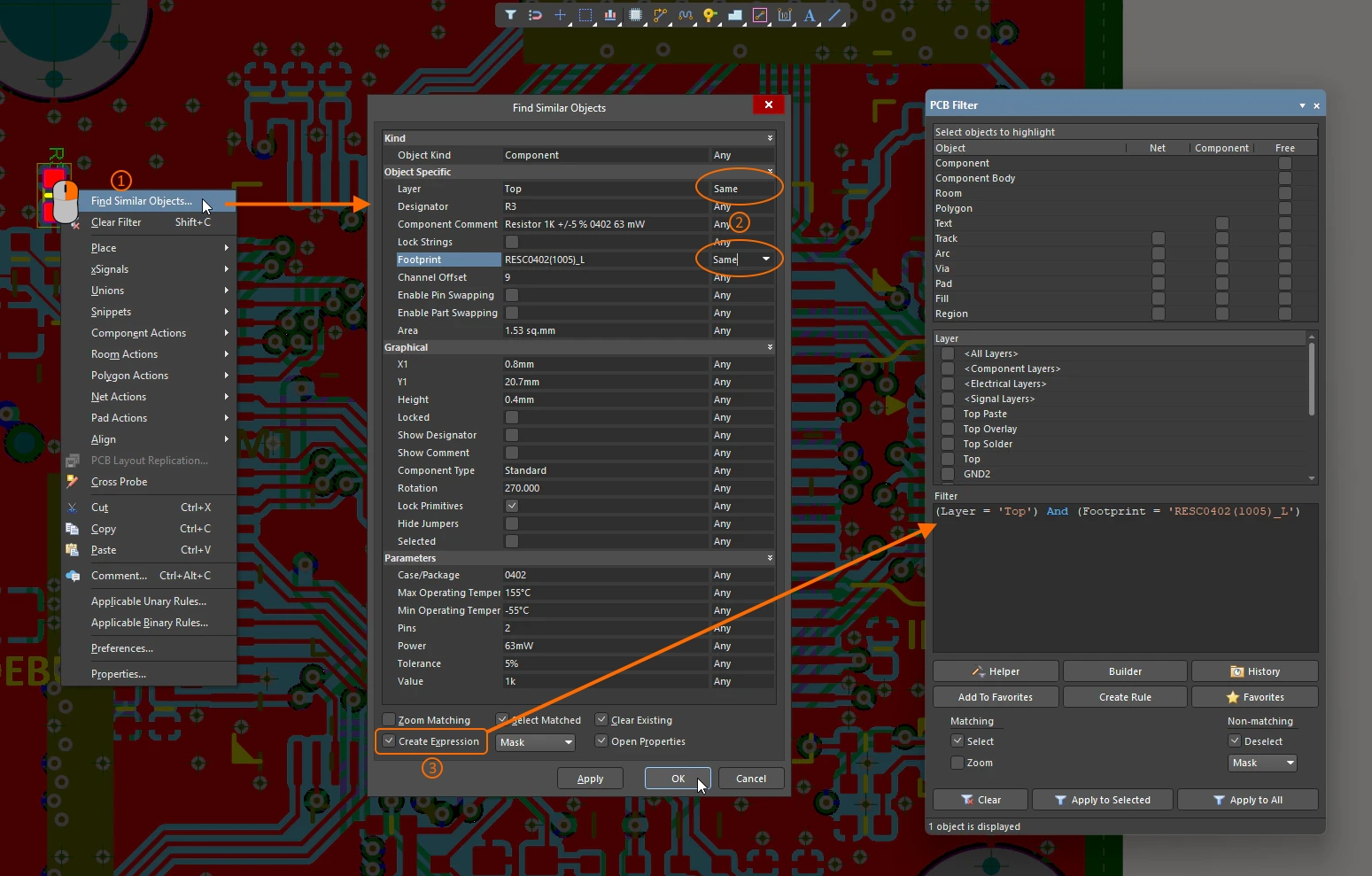
| Create a query from a search | A handy way to find objects like one that you are looking at (in the schematic or PCB editors) is to right-click on the object and select Find Similar Objects from the context menu. The Find Similar Objects process uses the attributes of that target object as a reference for finding all other objects with similar characteristics, as configured in the Find Similar Objects dialog. Behind the scenes the process creates a query to find those objects, and if the Create Expression option is enabled in the dialog, then that query will be loaded into the PCB Filter panel, where you can save it as a favorite or use it in a design rule ( Learn more about the Find Similar Objects tool. |
 ).
).Learn more about Working with the Query Language.
Rule Priority
To simplify the process of defining and managing rules, the approach is to define general rules that cover broad requirements, and then override these with specific rules for specific situations. When when an object is targeted by multiple rules of the same type, a contention exists. All contentions are resolved by the priority setting. The system goes through the rules from highest to lowest priority and picks the first one whose scope expression(s) match the object(s) being checked.
To manage this process, you need to be able to prioritize the rules in order to indicate which one to use when an object is targeted by multiple rules of the same type.

Change rule priorities in the Edit Rule Priorities dialog.
Setting the Rule Priorities |
|
| Priority of rules | The lower the priority number, the higher the priority. Priorities are only applied within a rule-type (across all rule sets). For example, Routing Width priorities are not considered when Differential Pair Routing priorities are being checked. Note that the priorities of all Routing Width rules in all rule sets are ranked. More about rule sets. |
| Approach to prioritizing | Typically, the broader the scope of the rule (for example All), the lower the priority it needs. This rule can then be overridden for a specific net (or a class of nets) by adding another rule of the same type, but with a higher priority. The priority number is not directly user-defined, instead the priority of the rules is configured by clicking the Priorities button in the PCB Rules and Constraint Editor (as shown above) and then increasing or decreasing the priority of the selected rule in the Edit Rule Priorities dialog. |
| What happens when you click the Priorities button | The priorities are managed in the Edit Rule Priorities dialog, as shown above. The dialog automatically loads all the rules of the current rule-type. If a rule category or rule set is selected in the tree on the left when the Priorities button is clicked, the software automatically chooses the next rule-type below. |
| Priority of a new rule | When adding a new rule to a rule type that already contains one or more existing rules, the priority will be set to 1 (the new rule is given the highest priority). When a specific rule is duplicated, the copy is given the priority below the source rule. |
| Checking the priorities | On the left side of the PCB Rules and Constraint Editor, when a specific rule-type is selected in the tree, the rules of that type are always listed in order of priority (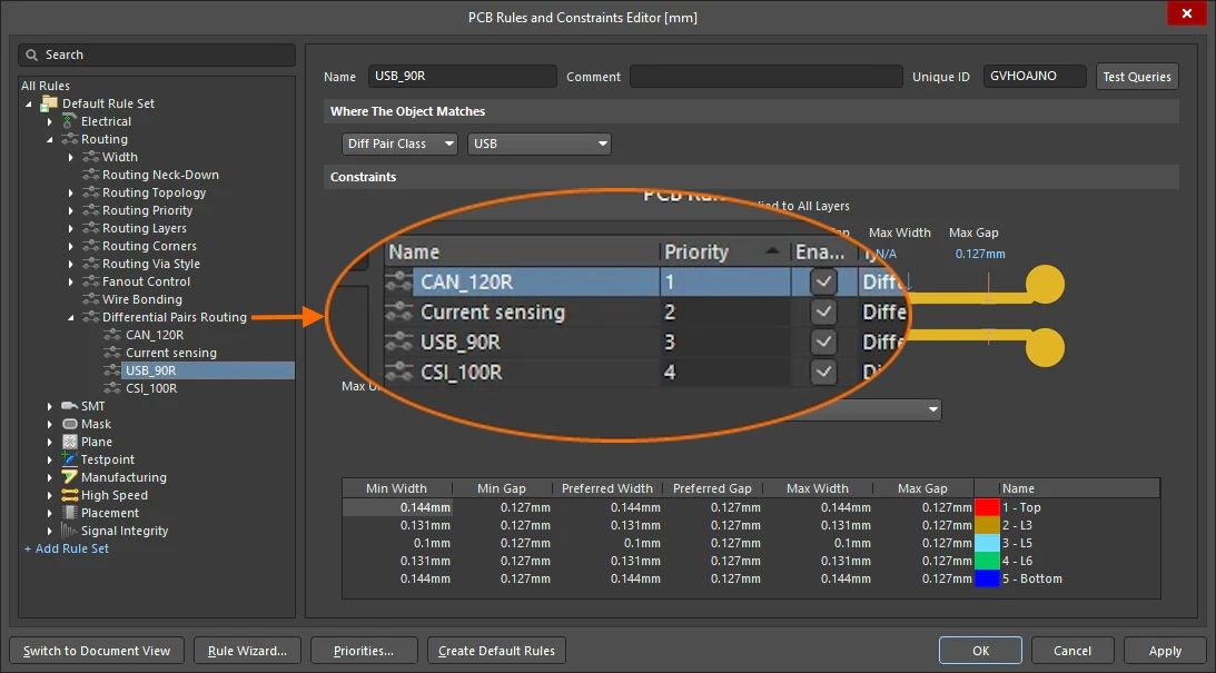 ). On the right side of the dialog, when the list displays a specific rule-type, the Priority column heading can be clicked to sort the list by that column ( ). On the right side of the dialog, when the list displays a specific rule-type, the Priority column heading can be clicked to sort the list by that column (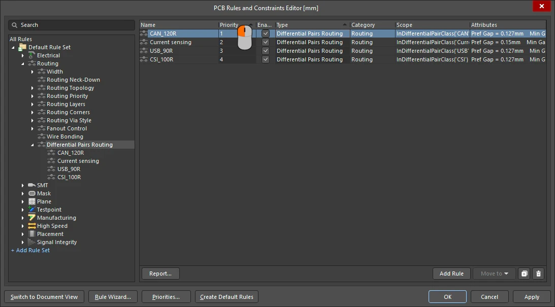 ). ). |
| Examining the priority in the design space | The design rules system automatically selects the highest priority applicable rule when a rule-related task is being performed. For example, when you right-click on an object and select Applicable Binary Rule in the context menu, the dialog displays the highest priority applicable rules (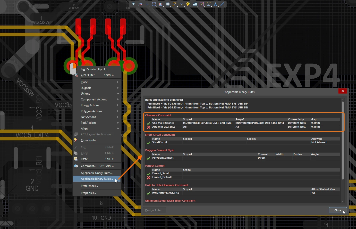 ). ). |
Managing the Rules
Rules are managed in the PCB Rules and Constraint Editor, either using the right-click context menu or by editing directly in the dialog fields.
 An example of the system flagging an invalid design rule, in this case, an erroneous scope query expression.
Managing the Design Rules |
|
| Modifying an existing rule | To arrive at the final working set of rules often involves a few key refinements here and there – typically this involves adjusting the scope to ensure the target design objects are being 'picked up' by the rule. To edit an existing rule in the PCB Rules and Constraints Editor dialog – click once on the rule name in the tree on the left, or double-click on the rule in the grid view on the right – and make changes as necessary to its scoping and constraints. Changes made to existing rule definitions are highlighted in both the folder-tree pane and the applicable summary lists. Such entries are distinguished by the rule name becoming bold and an asterisk displayed to the right of the name ( |
| Flagging Invalid Rules | If a rule is detected as being invalid by the system – for example, it has an issue with its scoping query expression or a value for a constraint that is not allowed – it will be flagged as being invalid. Such a rule will be highlighted in red within the PCB Rules and Constraints Editor dialog both in the left-hand rule tree, and any summary view (rule category or rule type) in which the rule appears, as shown above. In addition, the text for the rule type and rule category is also presented in red within the left-hand rule tree. So if you have collapsed an area of the rule tree that contains an invalid rule, you will still be alerted to it at a higher level in the hierarchy. A warning message will also appear if you attempt to close the dialog ( |
| Disabling Rules | In the rules-driven environment of the software's PCB editor, it is not uncommon to build up a rather impressive and comprehensive array of rules with which to successfully constrain your boards. For whatever reason, you may wish to disable some rules; perhaps they are not applicable to the board in question or they need to be temporarily disabled to ease the load on the Design Rule Checker. Disabling is a good way of keeping such rules just in case they are needed again in the future ( To disable a rule, toggle the corresponding Enabled option for that rule in one of the relevant summary lists on the right-hand side of the PCB Rules and Constraints Editor dialog. A disabled rule also will appear 'grayed-out'. |
| Deleting a Rule | To delete a single design rule from within the PCB Rules and Constraints Editor dialog:
|
 ).
). ).
). button below the list. The rule name will appear bold with strike-through highlighting to distinguish it as being a deletion that is yet to be 'applied'
  ).
).Exporting and Importing Rules
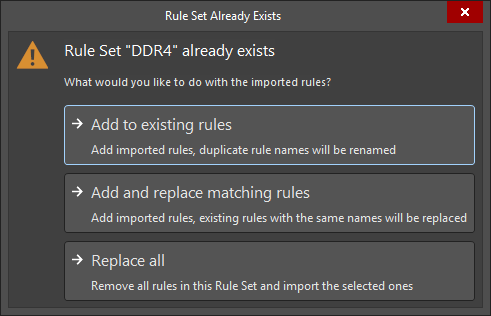
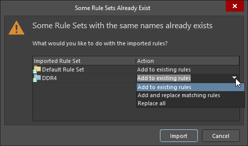
Design rules can be exported from and imported to the PCB Rules and Constraints Editor dialog. This allows you to save and load favorite rule definitions between different designs.
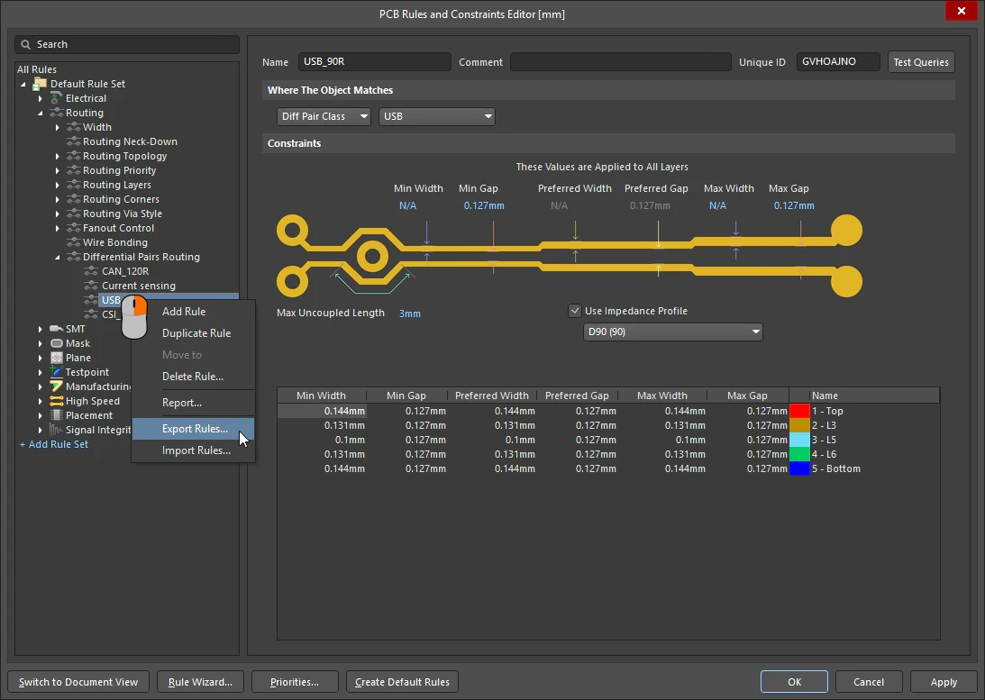 Rules can be exported and imported in the PCB Rules and Constraints Editor.
 ).
). ).
). in the Select Design Rules dialog
  ).
). ).
).Design Rules Report
A report of the currently defined design rules can be generated from within the PCB Rules and Constraints Editor dialog. The report can cater to all rule categories, a specific rule category, or a specific rule type, depending on the selected entry in the folder-tree.
Right-click and select Report in the context menu to generate a report. The Report Preview dialog will open with the appropriate report loaded. Use the dialog to inspect the report using various page/zoom controls and then print or export it to a file.
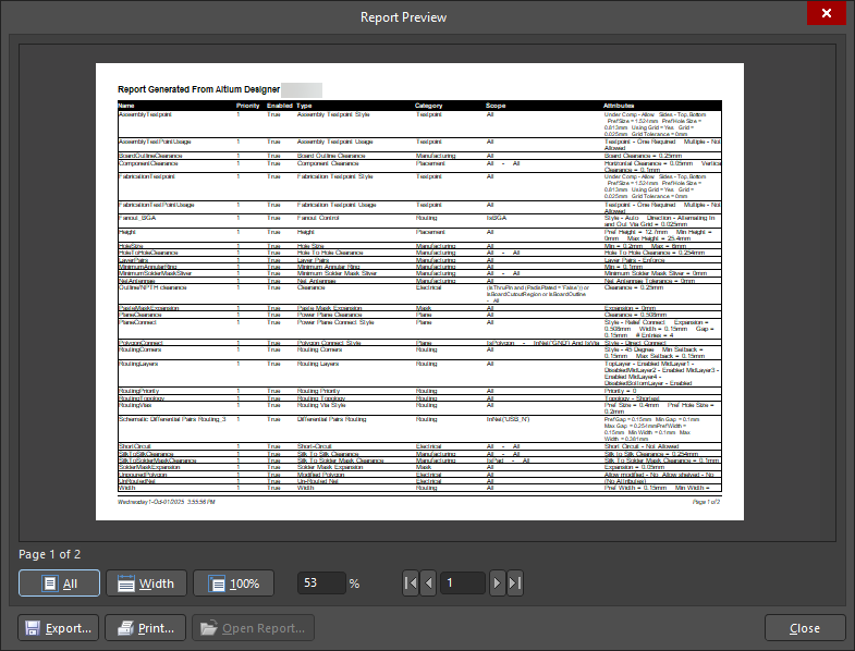
Generate a PCB Rules Report.
Options and Controls of the Report Preview Dialog
| Preview Window | The main region of this dialog presents the preview of the generated report. The report can be manipulated using the various controls below the window and on the right-click menu. The report can also be zoomed and panned using the standard Windows shortcut combinations. |
| Page x of x | The first x is the current page being viewed; the second x is the total number of pages in the report. |
| All | Click this button to have the page sized to fit within the available preview window. As you resize the dialog (and therefore the preview window), the page will resize to stay fully visible. |
| Width | Click this button to have the page sized to fit within the horizontal extents of the available preview window. As you resize the dialog (and therefore the preview window), the page will resize to stay fully visible across its entire width. |
| 100% | Click this button to have the page set to full size (100%). |
| % | Use this field to zoom in or out, full size is 100%. Zooming can also be performed using Ctrl+mouse wheel or the Page Up and Page Down keys to zoom in and out, respectively. You can pan around the zoomed view by holding down right-click and dragging the document. Use Shift+mouse wheel to scroll horizontally and mouse wheel to scroll vertically. |
| Page Navigation Controls | this cluster of controls collectively provide another means of navigating the pages of the report. The controls allow you to jump to the first, previous, next and last pages in the document respectively. Alternatively, you can enter the page number directly in the text box and press Enter. |
| Export | Click to access the Export Report From Project dialog where you can save the report with a specific location, name and export format. The following formats are supported:
|
| click this button to print the report. The standard Print dialog will appear from where you can specify page range and number of copies. | |
| Open Report | click this button to open a generated report in the application you specified in Export. This button is available only after clicking the Export button. |
| Right-Click Commands | These commands are also available on the right-click menu. |
Grouping Rules into Rule Sets
Rule sets allow for the efficient grouping and reuse of a set of design rules specific to, for example, an interface or manufacturer. You can quickly:
-
Create a new rule set or duplicate an existing set (and then modify further as required).
-
View and manage the constituent rules within a set, with the ability to move a rule between sets.
-
Switch between applied sets of rules – enabling/disabling sets as desired.
-
Export/import rule sets for optimal portability. More about exporting and importing design rules.

An example of a user-defined DDR4 rule set that groups design rules related to the DDR4 interface.
Working with Rule Sets |
|
| Default Rule Set | A PCB document includes a Default Rule Set. It cannot be renamed, disabled, or deleted. The Default Rule Set is distinguished by the |
| Create a new Rule Set | To create a new rule set, click the + Add Rule Set control at the bottom of the left-hand tree in the PCB Rules and Constraints Editor dialog or right-click the All Rules entry at the top of the tree and select the Add Rule Set command from the context menu ( |
| Rename a Rule Set | A user-defined rule set can be renamed by right-clicking its entry in the left-hand tree of the PCB Rules and Constraints Editor dialog and selecting Rename from the context menu. Provide a new name for the rule set in the New Name field of the Rename dialog that opens and click the Renamed rule sets are distinguished in the folder-tree pane by the rule set name becoming bold and an asterisk displayed to the right of the name. The asterisk is used to reflect that the rule set is an existing rule set that has been modified, rather than a newly created rule set (which is displayed in bold without an asterisk). |
| Duplicate an existing Rule Set | To create an identical copy of an existing rule set, right-click the existing rule set and choose Duplicate Rule Set ( The duplicate rule set will have the same design rules as the original rule set. Each design rule within the duplicate rule set will be named the same as the original, with the addition of a suffix (e.g., |
| Move rules between Rule Sets | To move existing rules between rule sets:
|
| Disable a Rule Set | To exclude design rules within a particular user-defined rule set from DRC, right-click its entry and select Disable Rule Set from the context menu. The entry of a disabled rule set will be grayed-out in the tree, and the Disabled text will be shown at its right. All entries of rule categories, rule types, and individual design rules of a disabled rule set will also be grayed-out in the tree, and design rule entries will be grayed-out in relevant summary lists on the right-hand side of the PCB Rules and Constraints Editor dialog ( |
| Delete a Rule Set | To delete user-defined rule set (along with its design rules), right-click the required rule set in the left-hand tree and choose Delete Rule Set from the context menu. The rule set name and names of its individual design rules will appear bold with strike-through highlighting to distinguish them as being a deletion that is yet to be 'applied' ( |
| Priority across Rule Sets | Design rules of each type have a priority that is global across all rule sets. That means that if an object in the PCB document is covered by more than one rule, the highest priority rule will apply, irrespective of the rule set it belongs to. For more information about managing rule priorities, refer to the Rule Prioritization section above. Note that design rules from specific rule sets can be force-checked during a Batch DRC, if required. For more information, refer to the Setting Up & Running a DRC page. |
 icon in the left-hand tree of the PCB Rules and Constraints Editor dialog, while user-defined rule sets have the
  icon.
icon.
 ).
). button. An entry for a new rule set (and its structure of rule categories and rule types) will appear in the tree. The rule set name will appear bold to distinguish it as being new and yet to be 'applied'.
 button
  ).
). ).
). button. An entry for a duplicate rule set (and its structure of rule categories and rule types) will appear in the tree. The rule set name and names of its individual design rules will appear bold to distinguish it as being new and yet to be 'applied'.
 button below the list and select the rule set to which the rule is required to be moved from the menu that appears. Alternatively, right-click the rule in the summary list and then select the required rule set from the Move to submenu of the context menu
  ).
). ).
). ).
).Defining Rules on the Schematic
For a project using design rules (rather than the Constraint Manager), rules can be added to the schematic by adding it as a parameter. For schematic objects that include parameters, such as a component, the rule is added as a parameter. Otherwise it must be added using a Parameter Set object.
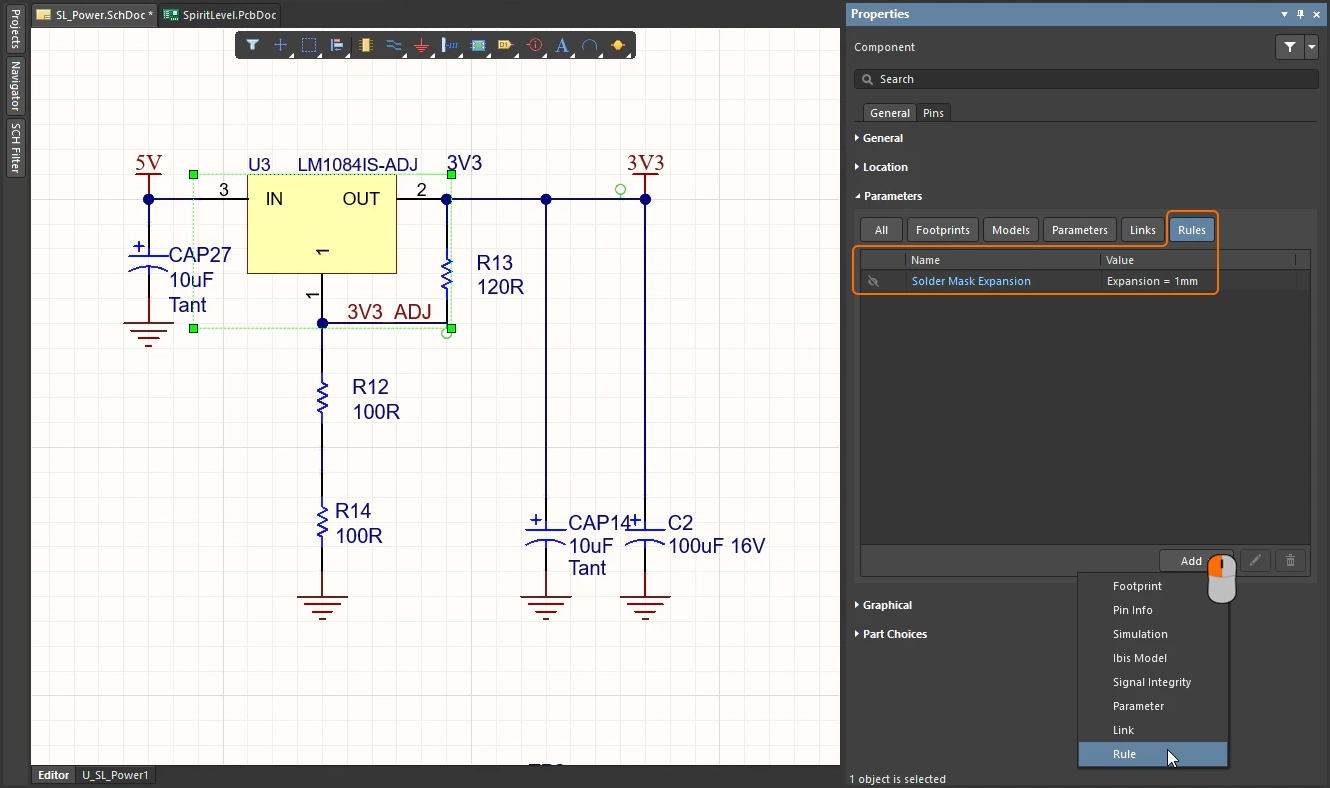
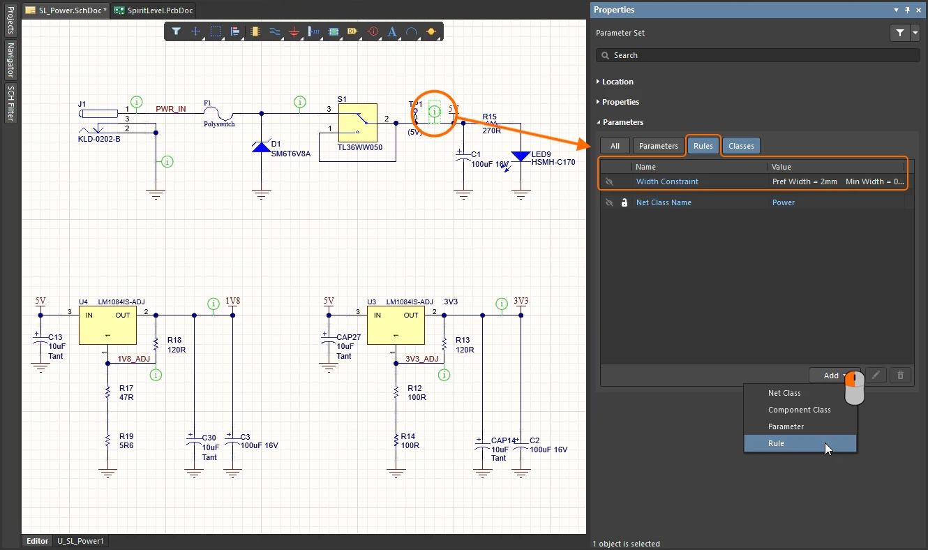
Defining Rules on the Schematic |
|
| Schematic objects that include parameters | For schematic objects that include parameters, such as components, the rule is added as a parameter, as shown in the first slide in the slideshow above. |
| Schematic objects that do not include parameters | For objects that do not include parameters the rule is added to a Parameter Set object, as shown in the second slide in the slideshow above. This includes objects such as wires, busses, harnesses, net labels, and others. Learn more about PCB-related schematic design directives. |
| Scope of the PCB rule | To scope the PCB rule that is created, the identity of the object it is attached to is used.
|
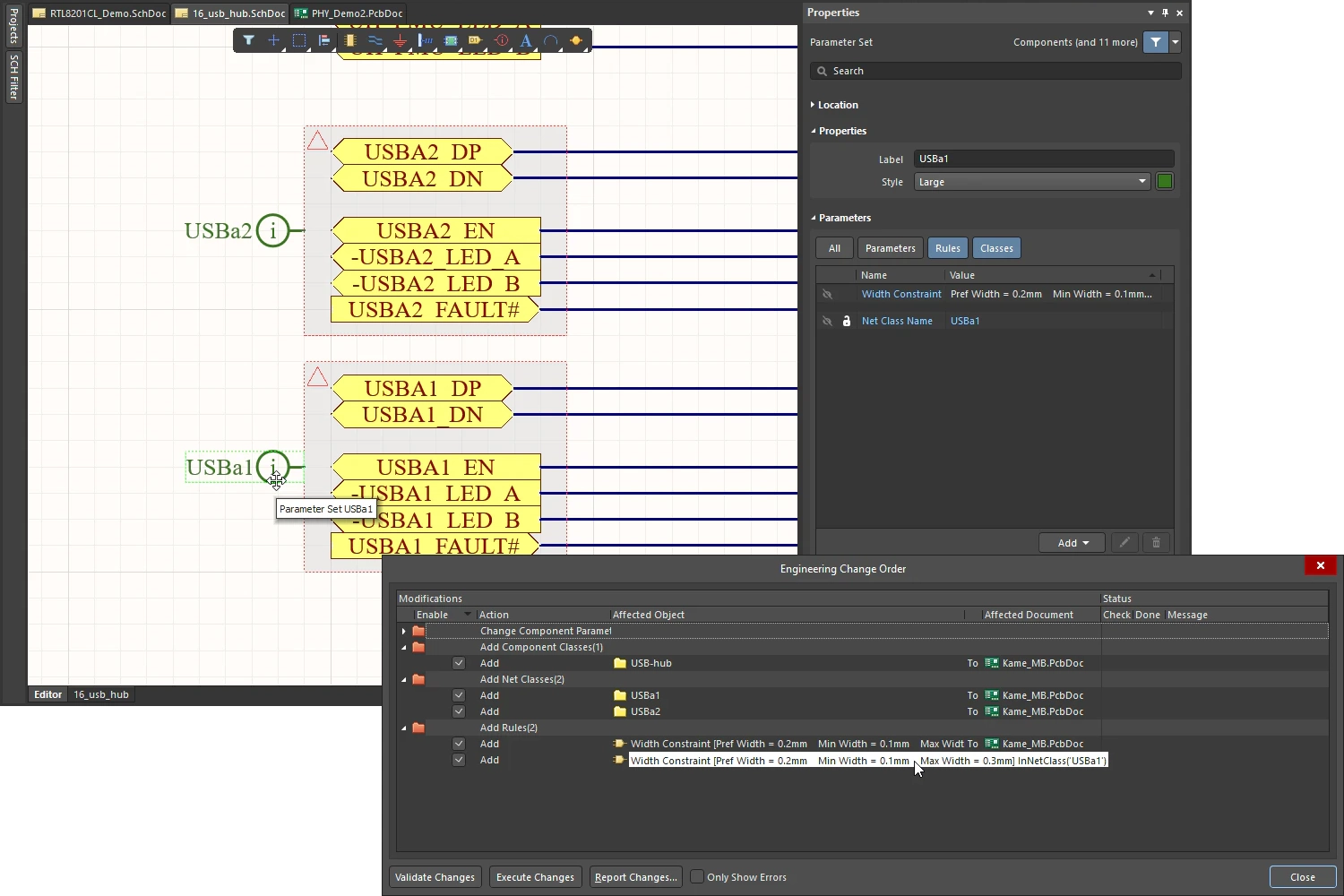 ).
).Checking the Rule Application
Depending on the board design, it may include design rules defined with scopes that range from the very simple to the very complex. It is a good idea to check that the rules defined do actually target their intended objects. Care at the rule definition stage can save wasted time and effort tracing violations caused through incorrect rule scoping.
There are essentially two methods for verifying rule scopes – either by selecting design objects and interrogating the rules that currently apply to them; or by taking a rule (in different locations or the software) and observing which objects fall under its scope.
From an Object's Perspective
For any placed object in the current design, you can quickly access information about which design rules apply to that object. Position the cursor over the object, right-click then select either Applicable Unary Rules, or Applicable Binary Rules.
All defined design rules that apply to the selected object(s) are listed in either the Applicable Unary Rules or Applicable Binary Rules dialog.
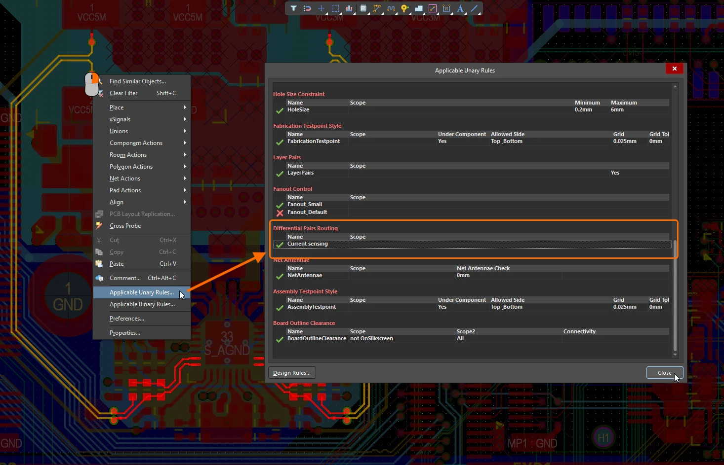
What Rules Apply to this Object? |
|
| Applicable Unary Rule | When this command is selected, the object that was under the cursor when you performed the right-click action is taken as the object of interest – the Applicable Unary Rules dialog will display all design rules applying to this object. Position the cursor before selecting the command. |
| Applicable Binary Rule | When this command is selected the Status bar will prompt you to Choose first object, then once that is done, Choose second object. The Applicable Binary Rules dialog will display all design rules applying between the two objects you clicked on. |
| Understanding the dialog | Each rule listed in the dialog will have either a check ( |
 )
) )
)From a Rule's Perspective
The PCB editor includes two mechanisms to work from the rules perspective and examine the objects targeted by that rule, using the PCB Rules and Violations panel, or from within the PCB Rules and Constraint Editor dialog.
Checking via the PCB Rules And Violations Panel
The PCB Rules And Violations panel lists all currently defined rules for the design. Configure the navigation options at the top of the panel, then click to browse the objects targeted by any of the currently defined design rules.
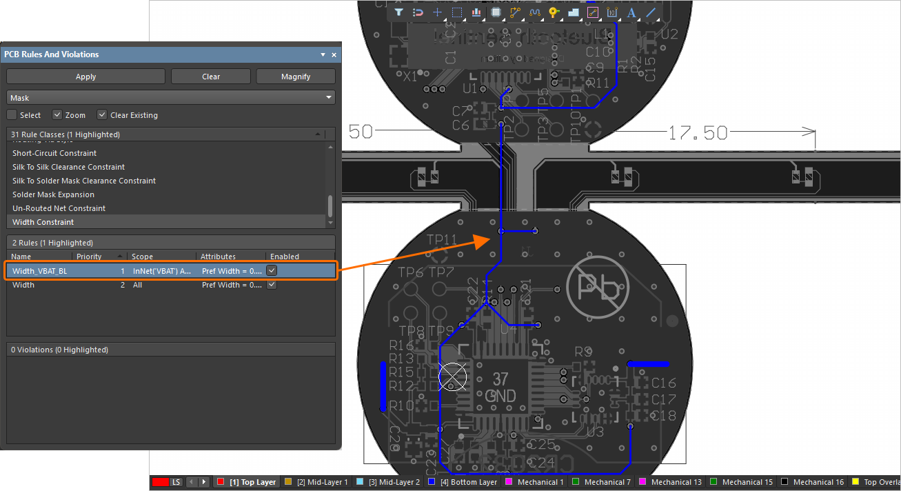
An example of using the PCB Rules And Violations panel to check which objects a selected rule applies to.
Working in the PCB Rules and Violations panel |
|
| Rule Classes section | Click once to display only rules of the selected class, or click [All Rules] to reset the display to list all current design rules in the Rules section. |
| Rules section | For the rules defined for this board, this section lists [All Rules], or rules of the currently selected Rule Class.
|
| Violations section | If there are violations present for any rules of the currently selected rule class or rule after running a DRC, they will be listed in the third section of the panel.
Learn more about Interrogating & Resolving Design Violations. |
| Controlling the response | Use the controls at the top of the panel to define how the display responds when you click on a rule in the list.
|
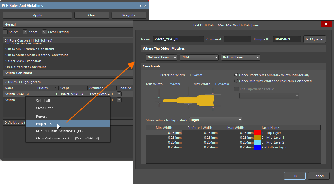 ).
).Checking via the PCB Rules and Constraints Editor Dialog
The PCB Rules and Constraints Editor dialog includes a query testing facility, allowing you to quickly see what objects a particular rule applies to. Click the  button at the top-right of the dialog for the rule you want to test. The Test Queries Result dialog will appear.

Quickly view the objects captured by a rule's scoping expression using the Test Queries feature.
Test Queries Result dialog |
|
| Expression result | The number of objects falling under the scope of the expression. |
| Objects applicable to rule | The number of applicable objects based on the expression and type of the current rule. |
| Expression and rule priority (for a unary rule only) |
The number of objects based on the expression, type, and priority of the current rule (i.e., when there is a rule of a higher priority, objects scoped by that rule will not be taken into account for this value). |
| Rules with highest priorities (for a unary rule only) | If there are rules with higher priorities, their list will be presented in the dialog, along with the number of objects applicable to them (i.e., their Expression and rule priority values). |
| Working in the dialog | Click on a link on the right side of the dialog to filter to the applicable objects in each case directly in the design space. Use the Mask drop-down to select Normal, Mask, or Dim depending on how you want the affected objects to be highlighted in the PCB document. If Zoom is checked, the PCB document will also zoom into the affected components. |