A large variety of outputs can be generated for and from a PCB design and each output type has its own settings. The best way to manage this multitude of outputs is to use an Output Job file, or 'OutJob' as it is more commonly known.
An OutJob is a pre-configured set of outputs. Each output is configured with its own settings and its own output format, for example, output to a file or to a printer. The settings for these outputs are stored in the OutJob file, which is an ASCII file that becomes part of the project.
OutJobs are very flexible – they can include as many or as few outputs as required and any number of OutJobs can be included in a project. The best approach is to use one OutJob to configure all outputs required for each specific type of output being generated from the project. For example, all outputs required to fabricate the bare board go in one OutJob, all outputs required to assemble the board go into a second OutJob, and so on.
OutJobs also can hold validation-type checks, such as ERC and DRC reports. These reports are useful for a final thumbs-up check just before generating the outputs and can then be held as a record that the design was ready for release.
Portable in nature, OutJobs can also be re-used between designs by copying the Output Job file from one project to the next one then resetting the Data Source as required.
Summarizing, using an OutJob has a number of advantages:
-
All outputs are configured in and generated from a single location.
-
Multiple outputs can be streamed into a single output file if required - for example, schematic prints and PCB layout prints can be output into the same PDF.
-
OutJobs are used in a Workspace project, allowing for controlled release of the design.
-
OutJob files can be copied from one project to another, insuring that your company's preferred output settings are always used.
Adding and Defining an Outjob
OutJobs are defined using the OutputJob editor. Create a new Output Job file by:
-
Using the File » New » Output Job File command.
-
Right-clicking on the project name in the Projects panel and choosing Add New to Project » Output Job File from the pop-up menu that appears.
Output Job files, when added to a project, appear in the Projects panel under the Settings\Output Job Files sub-folder.
Creating a Workspace Outjob
You can also take advantage of Workspace-hosted content and create an Output Job in your connected Workspace:
-
Open the Templates tab of the Data Management – Templates page of the Preferences dialog.
-
Select the Output Job command from the menu of the Add button or the context menu of the template grid.

-
After selecting the command, click OK in the Close Preferences dialog that opens to close the Preferences dialog and open the temporary OutputJob editor. A planned revision of the new output job will be created automatically in a Workspace folder of the Output Jobs type.
-
Configure the output job as required, as described below on this page.
-
Save the output job to the connected Workspace by selecting the File » Save to Server command from the main menus. The Edit Revision dialog will appear, in which you can define the Name and Description of the output job being created in the Workspace, and add release notes as required.
Saving an Existing Local Output Job to the Workspace
If you have an existing output job file (*.OutJob), you also have the ability to save this file directly to the Workspace. The process is as follows:
-
Open the output job file within Altium Designer.
-
Choose the File » Save to Server command from the main menus.
The file must be locally saved (File » Save) prior to saving to the Workspace.
-
The Choose Planned Item Revision dialog will appear. Use this to choose the target Workspace Output Job into the next revision (or an established revision in the Planned state) of which the file will be saved, then click OK.
If the target Workspace Output Job doesn't exist, you can create it through the Choose Planned Item Revision dialog on-the-fly in the chosen Workspace folder by right-clicking in the revision list region of the dialog (or, if the folder does not contain any item yet, by clicking the Add an item control) and selecting the Create Item » Outputjob command. If doing so, be sure to disable the Open for editing after creation option (in the Create New Item dialog). Otherwise, you'll enter direct editing mode.
-
The Edit Revision dialog will appear, in which you can define Name, Description, and add release notes as required.
-
After clicking OK, the file will be saved and stored in the revision of the Workspace Output Job.
If the required output job file to be saved to the Workspace resides in the Local Template folder (denoted at the bottom of the Data Management – Templates page of the Preferences dialog) and is listed under the Local entry of the template grid, it can be migrated to a new Workspace Output Job by right-clicking on it and selecting the Migrate to Server command. Click the OK button in the Template migration dialog to proceed with the migration process – as stated in this dialog, the original project file will be added to a Zip archive in the local template folder (and hence it will not be visible under the Local template list).
Editing a Workspace Output Job
At any stage, you can come back to an Output Job in the Workspace and edit it. From the Templates tab of the Data Management – Templates page of the Preferences dialog, right-click on the output job entry and choose the Edit command from the context menu. The temporary editor will open, with the output job contained in the latest revision of the Workspace Output Job opened for editing. Make changes as required, then save the output job into the next revision of the Workspace Output Job.
Adding a Workspace Output Job to a Project
A Workspace Output Job can be used in design projects.
Choose a revision of a Workspace Output Job to use from the Managed OutputJobs tab of the Project Options dialog. Click the  button – the Select configuration item (Output Jobs) dialog will appear, listing the latest revision of all Output Jobs in the Workspace that are available to you. Choose the required Output Job and click OK.

Manually choosing a revision of an outputjob from within the Managed OutputJobs tab of the Project Options dialog.
Options and Controls of the Select configuration item (Output Jobs) Dialog
Grid - the available configuration items are listed in terms of Name, Description, Item Revision, and Revision State. Select the desired configuration item from the list then click OK to add the selected item to the Managed OutputJobs tab of the Project Options dialog.
Right-click Menu
Continue adding further revisions of different Output Jobs as required. After clicking OK to exit the Project Options dialog, the chosen outputjob(s) will appear in the Projects panel. A Workspace OutputJob is distinguished in the Projects panel by the  icon.
icon.

The added revisions of outputjobs will be reflected in the Projects panel.
Using a Workspace Output Job as Part of an Environment Configuration
A Workspace Output Job can also be used as a configuration data item in one or more defined Environment Configurations. An environment configuration is used to constrain a designer's working environment to only use company-ratified design elements. Environment configurations are defined and stored within the Team Configuration Center – a service provided through the Workspace.
Once you have connected to the Workspace, and chosen (if applicable) from the selection of environment configurations available to you, Altium Designer will be configured, with respect to use of Output Job Configurations. If the chosen environment configuration has one or more defined outputjob revisions, then only those defined configurations can be used. If the chosen environment configuration applicable to you does not have any outputjob revisions specified/added, then these will remain manually definable. In other words, you are free to manually reuse a Workspace-based Output Job Configuration and/or use local templates. For more information, see Environment Configuration Management (Altium 365 Workspace, Enterprise Server Workspace).
Under the enforcement of an environment configuration, Altium Designer will be configured, with respect to use of Output Jobs, in the following areas.
-
Project Options Dialog – revisions of outputjobs are specified for use from the Managed OutputJobs tab of the Project Options dialog, in much the same way when reusing them manually. The difference with their use under management of an environment configuration is that you can only add those revisions of outputjob defined for that environment configuration.
-
Click the button – the Select configuration item (Output Jobs) dialog will appear.
-
Use the dialog to choose which OutJob to use for the project, from the list of outputjob revisions defined as part of the environment configuration currently in-force.
-
Add additional outputjob revisions as required.
-
With all outputjob revisions added as required, OK out of the Project Options dialog – the chosen outputjob revision(s) will appear in the Projects panel.
-
Creating a New OutJob File – while you are only able to reuse the outputjob revisions specified in the active environment configuration, you are still able to create new, file-based output jobs if required. Commands for creating a new OutJob – either using the File » New » Output Job File command, or right-clicking on a project's entry in the Projects panel and choosing Add New to Project » Output Job File, will therefore still be available for use.
-
Trying to use an Existing OutJob File – under configuration management, and when at least one OutJob is defined for the active environment configuration, this will no longer be possible. If you attempt to add an existing Output Job File to the project, by right-clicking on a project's entry in the Projects panel, choosing Add Existing to Project, and browsing for that file, a warning dialog will appear – alerting you to the fact that Output Jobs are being managed by the applied environment configuration, and that existing Output Job files cannot be added to the project.
When a Workspace Output Job is added to a project and opened, the OutputJob editor will reflect that the file is a Managed OutputJob Document, with an indication of the Item Revision, its description, and the parent Workspace in which that Output Job resides.

The Output Job Editor when viewing a Workspace Output Job.
For a Workspace Output Job, any controls that would otherwise effect its modification in some way, are disabled. So the following abilities ARE NOT available:
-
Addition of new Output Generators.
-
Configuration of existing Output Generators.
-
Cut, copy, paste, duplication or deletion of an existing Output Generator.
-
Addition of new Output Containers or Hard Copy Jobs.
-
Configuration of an existing Output Container or Hard Copy Job.
-
Cut, copy, paste or deletion of existing Output Containers or Hard Copy Jobs.
-
Toggle the inclusion state of an Output Generator with respect to a valid Output Container or Hard Copy Job.
You can, however, still determine variant usage for the OutJob.
Right-click anywhere within the main
Outputs region of the editor, then choose
Document Options from the context menu. The
![]() Document Options dialog
Document Options dialog will open, providing information about the chosen OutputJob file: which revision of the Outputjob Item is being used, its lifecycle state, and whether it is the latest revision or not. Also shown is the source Workspace in which that OutputJob resides. Click the
Show in Explorer button to access the
Explorer panel, with the revision of the Outputjob loaded ready.
Elements of an OutJob
There are three steps to configuring an OutJob:

Constituent elements of the OutJob, all defined and managed within the OutputJob Editor.
-
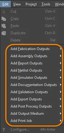
Add and configure the required outputs – outputs are gathered into functional categories, such as Assembly Outputs, Fabrication Outputs, and Report Outputs. Strictly speaking, outputs are obtained by running an associated Output Generator, configured appropriately and using a specified document within the project (or the project itself) as its data source.
-
Add and configure the required output formats – generation of any given output type requires that output to be mapped to a corresponding (and applicable) output format. This takes the form of either one of the supported Output Containers (PDF, Folder Structure, Video) or Hard Copy (print-based output). Multiple outputs can be mapped to the same container or hard copy, and the user has control over where the output is generated and how (any media-related options associated with the container/hard copy).
-
Set the variant choice – Altium Designer allows the outputs of a PCB project to be driven using the base (non-varied) design or by nominating the use of a defined variant of that design. Either choose a variant per applicable output or a single variant to apply to all applicable outputs in the file.
Adding Outputs to an OutJob
Add a new output of the required type by clicking on the appropriate Add New [type] Output text at the bottom of a category then choosing the required output type from the pop-up menu. Alternatively, choose the relevant command entry from the main Edit menu.

Add each output that is required by selecting the appropriate Data Source.
Output types for which the appropriate source data is available in the project will be listed as available with all other output types listed as unavailable (grayed-out).
A second menu is provided from which you can specify the Data Source, i.e. which source document(s) to be used when the output is generated. Only applicable data sources are available for each output leaving less room for error.
The Data Source depends on the particular output. PCB-related outputs, such as PCB Prints, Gerber Files and Testpoint Reports, will use the PCB design document as the Data Source. The Data Source for a BOM could be a single, specific source schematic document, the PCB design document, or all source schematic documents. The latter is represented by the [Project] entry.
The Data Source can be changed at any stage after adding an output. Click on the current Data Source and a drop-down arrow will appear; choose an alternate source from the list.
For certain outputs, the Data Source list will include [Project Physical Documents]. Use this option if the physical design (the design as it will be implemented on the board) must be annotated differently from the logical design (the original schematics). This will be necessary if the design includes Device Sheets or if it uses multi-channel capabilities and a simple, flat annotation scheme is preferred.
The term "Project Physical Documents" refers to the physical or compiled view of the schematics.
When setting the Data Source for the Schematic Prints output, All SCH Documents relates to the printing of the set of all logical schematics in the project (the raw, uncompiled "Editor" view of each schematic). To print the set of all physical schematics in the project (the compiled document view(s) of each schematic), be sure to set the Data Source to [Project Physical Documents].
To form the list of outputs, you can also use Cut, Copy, Paste, Duplicate and Delete commands from the Edit main menu (or from the Help » Right Mouse Click Output Medium sub-menu or the Job Manager Toolbar toolbar) or the right-click menu of the Outputs region (multiple outputs can be selected using standard multi-select controls: Ctrl+click, Shift+click).
Note that the software does not use the Windows clipboard for normal cut/copy operations in OutputJob documents. Instead, a separate internal clipboard is maintained for this document type. Also, the internal OutputJob clipboard is entirely independent of the internal clipboards used by any other editors in the software. You can only cut/copy and paste between, or within, OutputJob documents.
Maximizing Reusability – Making Your Output Job Generic
A number of innovative features are available when configuring your outputs to make the resulting Output Job Configuration as generic as possible. By keeping an OutJob generic, you can effectively maximize its ability to be reused across future design projects.
Generic Data Source Names
Many output generators use a specifically-named underlying document as their source, from which the applicable output data is generated – for example, Gerber files generated from the PCB document FluxTriangulator.PcbDoc. However, doing so locks the Output Job Configuration to being useful only with that document's parent design project. To keep things non-specific, a generic entry for the underlying Data Source is available for selection across many of the output generators. The following table summarizes which output generators are supported, and the generic entry (entries) available.
| Category |
Output Type |
Generic Data Source Entry |
| Netlist Outputs |
All |
[Project] |
| Simulator Outputs |
Mixed Sim
SIMetrix
SIMPLIS |
[Project] |
| Documentation Outputs |
Composite
PCB 3D Print
PCB 3D Video
PCB Prints
PDF3D |
[PCB Document] |
| |
PDF3D MBA |
[MBA Document] |
| |
Schematic Prints |
[Project Physical Documents] |
| Assembly Outputs |
All |
[PCB Document] |
| Fabrication Outputs |
All |
[PCB Document] |
| Report Outputs |
Bill of Materials |
[Project]
[ActiveBOM Document] |
| |
Component Cross Reference
Export Comments
Report Project Hierarchy
Report Single Pin Nets |
[Project] |
| Validation Outputs |
BOM Checks |
[ActiveBOM Document] |
| |
Component states
Configuration compliance
Electrical Rules Check
|
[Project] |
| |
Design Rules Check
Differences Report
Footprint Comparison Report |
[PCB Document] |
| Export Outputs |
Ansoft Neutral (AutoPCB)
Ansys EDB
AutoCAD dwg/dxf PCB
Export IDF
Export PARASOLID
Export STEP
Export VRML
Hyperlynx (AutoPCB)
MathWorks (AutoPCB)
P-CAD ASCII (AutoPCB)
Save As/Export PCB
Specctra Design PCB |
[PCB Document] |
| |
MBA Export PARASOLID
MBA Export STEP |
[MBA Document] |
| |
AutoCAD dwg/dxf Schematic
OrCAD v7 Capture Design (AutoSCH)
P-CAD V16 Schematic Design (AutoSCH)
Save As/Export Schematic |
[Project] |
| PostProcess Outputs |
Copy Files |
[Project] |
Layer Classes
You have the ability to add named layer classes to configurations for the following output generators:
-
PCB Prints
-
Assembly Drawings
-
Drill Drawings
-
Final
-
Gerber Files
-
Mask Set
-
Power-Plane Set
This makes these output generators generically reusable. For example, add a class 'signal layers' and refer to it in the OutJob – any design that has a 'signal layers' class will be able to use that output generator without modification.
Configuring Outputs
Depending on the specific output type, options may be available to configure the associated output generator providing more control over the generated output. Where configuration options are available, they can be accessed in one of the following ways:
-
Double-click directly within the row for the required output.
-
Right-click on the required output then choose Configure from the context menu.
-
Select the required output then use the keyboard shortcut Alt+Enter.
-
Select the required output then choose the Edit » Configure command.
If multiple outputs are selected, the configuration dialog associated with the last selected (currently focused) output will appear.
After launching the command, the associated configuration dialog will appear. Use the dialog to define setup options for the particular output files you wish to generate. Any options defined will be used when that output is next generated.

Different Output Generators have unique dialogs to configure precisely what gets generated.
The type of dialog (and indeed whether a configuration dialog appears at all) depends on the output you have selected. An output that generates data directly will have no dialog appear when this command is used (e.g. generation of a Design Rules Check validation report).
For outputs that can be used to generate hard copy (i.e. printed output sent to a printing device), access can also be made to a dialog for defining page properties. Either right-click on the output then choose
Page Setup from the context menu or select the output then use the
File » Page Setup command.
Available Output Types
Below is a summary of the available output types. A link to the relevant documentation describing configuration of the specific output is included where applicable.
Netlist Outputs
Netlists describe the logical connectivity between components in the design and are useful for transferring the design to other design platforms. A large variety of netlist formats are available.
The majority of output entries to generate netlist formats are only available, provided the associated functionality is installed as part of your Altium Designer installation. For more information, refer to the Interfacing to Other Design Tools page.
Simulator Outputs
The SPICE netlist is a textual representation of the circuit. To add a netlist output to the active OutputJob file, select a command from the Edit » Add Simulator Outputs sub-menus or the menus associated with the [Add New Simulator Output] control, at the bottom of the Simulator Outputs region, in the main job configuration window.
Documentation Outputs
-
PCB Prints - configure any number or printouts (pages), with any arrangement of layers and display of primitives, use this to create printed outputs such as assembly drawings.
-
PCB 3D Prints - views of the board from a three-dimensional view perspective.
-
PCB 3D Video - output a simple video of the board, based on a sequence of 3D key-frames defined in the PCB editor's PCB 3D Movie Editor panel.
-
PDF 3D - generate a 3D PDF view of the board, with full support to zoom, pan and rotate in Adobe Acrobat®. The PDF includes a model tree, giving control over the display of nets, components and the silkscreen.
-
Schematic Prints - schematic drawings used in the design.
-
Draftsman - Draftsman drawings added to the project.
Assembly Outputs
-
Assembly Drawings - component positions and orientations for each side of the board.
-
Pick and Place Files - used by robotic component placement machinery to place components onto the board. Note that the Report Generator can also be used to generate a Pick and Place file, and is highly configurable.
-
Test Point Report - as ASCII file, available in 3 formats, that details the location of each pad/via that has been nominated as a testpoint.
-
Wire Bonding Table Report - a CSV file that provides information in relation to die pads and bond finger pads used in a PCB that features wire bonding.
Refer to the Preparing Assembly Data page to learn more.
Fabrication Outputs
-
Report Board Stack - produces a board stack report summarizing the defined layer stacks and the layers used in the stackup.
-
Composite Drill Drawings - drill positions and sizes (using symbols) for the board in one drawing.
-
Drill Drawing/Guides - drill positions and sizes (using symbols) for the board in separate drawings.
-
Final Artwork Prints - combines various fabrication outputs together as a single printable output.
-
Gerber Files - creates manufacturing information in Gerber format.
-
Gerber X2 Files - a new standard that encapsulates a high-level of design information, with backward compatibility to the original Gerber format.
-
IPC-2581 File - a new standard that encapsulates a high-level of design information within a single XML file.
-
NC Drill Files - creates manufacturing information for use by numerically controlled drilling machines.
-
ODB++ - creates manufacturing information in ODB++ database format.
-
Power-Plane Prints - creates internal and split plane drawings.
-
Solder/Paste Mask Prints - creates solder mask and paste mask drawings.
-
Testpoint Report - creates test point output for the design in a variety of formats.
Refer to the Preparing Fabrication Data page to learn more.
Report Outputs
A number of reports such as BOM, project hierarchy report, and project comment PDF, can be prepared for the project or one of its documents.
-
Bill of Materials – creates a list of parts and quantities (BOM) in various formats required to manufacture the board.
-
Component Cross Reference Report – creates a list of components based on the schematic drawing in the design.
-
Report Project Hierarchy – creates a list of source documents used in the project.
-
Report Single Pin Nets – creates a report listing any nets that only have one connection.
Refer to the Preparing Reports page to learn more.
Validation Outputs
The software includes a number of validation checks, which can be included as an output, during output generation. Each produces an HTML report file.
Note that the setup for these validation reports is held in the OutputJob. When you configure a validation check elsewhere in the software the settings are held with that file - for example the settings for project error checking are stored in the project file, PCB DRC settings are stored in the PCB file.
Export Outputs
The software is able to export data into a large number of formats. The options available in this section of the OutputJob will depend on which exporters are currently installed in Altium Designer. Exporters are provided either as core functionality features or extensions.
For more information about changing installed core functionality, refer to the Installing & Managing page (Altium Designer Develop, Altium Designer Agile, Altium Designer).
For more information about managing extensions, refer to the Extending Your Installation page (Altium Designer Develop, Altium Designer Agile, Altium Designer).
PostProcess Outputs
This output type allows non-native Altium Designer file types to be included as part of the output. It copies the targeted files from within the project directory structure to the folder specified in the configured Folder Structure output container.
Refer to the Preparing PostProcess Outputs page to learn more.
Defining Output Format
Adding and configuring the outputs for an OutJob defines what is to be generated and how. The definition of where the generated output is to be written to is required, i.e. in which format the output is to be generated. Depending on the type of outputs being generated, this is handled using a combination of Output Containers and Hard Copy.
Output Containers
Outputs can be written (where applicable) to three types of Output Containers – a PDF, a specific-format of output file (such as a Gerber file) or a video.
A new OutJob will default to include one of each of these types of containers named PDF, Folder Structure, and Video. Any number of additional containers of these types can be added by clicking [Add New Output Container] or from the Edit » Add Output Medium sub-menu, and names can be edited for easy identification.
A new output container can also be created from one or more selected applicable outputs, by dragging and dropping the selection into the Output Containers or Hard Copy region - away from existing, defined output containers. The output(s) will automatically be linked.
To form the list of output containers, you can also use Cut, Copy, Paste and Delete commands from the Help » Right Mouse Click Output Medium sub-menu of the main menus or the right-click menu of the Output Containers or Hard Copy region.
Using the Paste As commands, a new output container can be created based on the content currently on the Output Job Editor's clipboard. The commands will only be available, provided the content on the clipboard is compatible - for example, only a copied print job, PDF output container, Folder Structure output container (if its associated outputs can be PDF'd), or copied output(s) that can be PDF'd, can be pasted as a new PDF output container.
Note that the software does not use the Windows clipboard for normal cut/copy and paste operations in OutputJob documents. Instead, a separate internal clipboard is maintained for this document type. Also, the internal OutputJob clipboard is entirely independent of the internal clipboards used by any other editors in the software. You can only cut/copy and paste between, or within, OutputJob documents.

Output Containers 'receive' generated output.
Configuring a Container
Click on a container to access additional controls, including the ability to configure the container. After clicking on the required container, click the Change link to access the Settings dialog associated with that particular type of container:
-
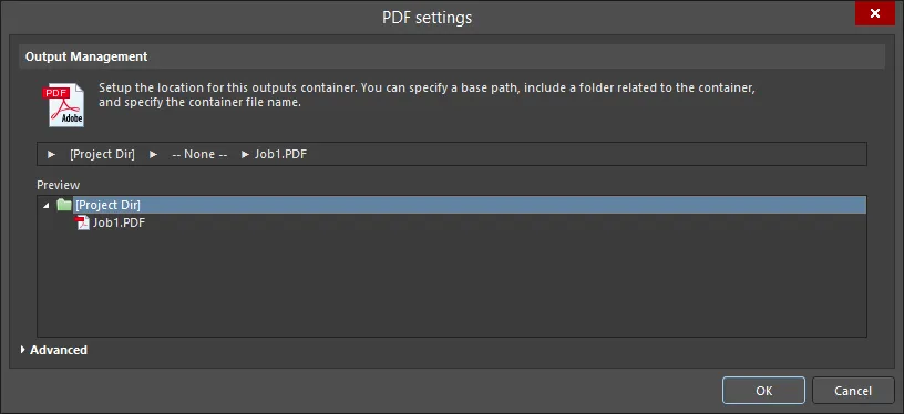
For a PDF output container, the PDF Settings dialog will appear.

The Advanced and Basic variations of the PDF Settings dialog
Options and Controls of the PDF Settings Dialog
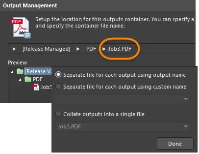
Output Management
Use this region to set up the location for this output container. You can specify a path, include a container folder related to the container, and specify the container's file name.
You can horizontally resize the windows described below by dragging the lower-right corner.
-
Release Managed - click to open a pop-up in which you can specify folder management.
-
Release Managed - select to make the PDF available to the PCB release system.
-
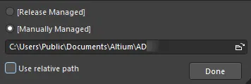
Manually Managed - select to set the PDF to be manually managed and stored in a local folder. By default, this will be a path specified in the Output Path field on the Options tab of the Project Options dialog.
-
File Location textbox - click the file browser button to browse for and select a target folder for the PDF. This option is available only when Manually Managed is selected.
-
Use relative path - enable this option to use a relative path in the File Location textbox. This option is available only when Manually Managed is selected.
-
Done - click to complete the configuration.
-
None - click to open a pop-up in which you can configure the container folder for the PDF.
-
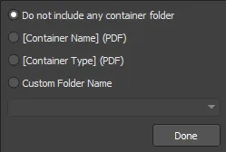
Do not include any container folder - select to not include a container folder.
-
[Container Name] (PDF) - select to use the container name as the container folder name.
-
[Container Type] (PDF) - select to use the container type as the container folder type.
-
Custom Folder Name - select to customize the folder name. Click the drop-down arrow to open a drop-down list from where you can choose a naming string for the folder. You can also directly enter the folder name in the textbox.
-
Done - click to complete the configuration.
-
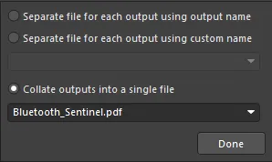
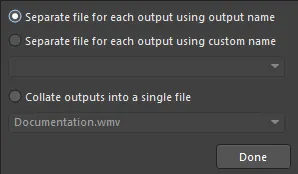
[Filename].pdf - click to open a pop-up in which you can configure the PDF output.
-
Separate file for each output using output name - select to create a separate file for each output using the output name specified.
-
Separate file for each output using custom name - select to create a separate file for each output using the custom name specified in the textbox below. Click the drop-down arrow to open a drop-down list from where you can choose a naming string. You can also directly enter the custom name in the textbox.
-
Collate outputs into a single file - select to collate the outputs into a single file. Click the drop-down arrow to open a drop-down list from where you can choose a naming string for the file. You can also directly enter a custom name in the textbox.
-
Done - click to complete the configuration.
-
Preview - this region shows a preview of the PDF location. As changes are made in the above pop-up dialogs, the preview window is updated so you can immediately see how your changes affect the structure of the folders.
Advanced Version Commands
-
Zoom - use the slider bar to control the zoom level (Far to Close) when jumping to components or nets.
-
Page Size And Orientation - use these settings to control whether the page size and orientation are configured from the Page Setup dialog or from the source documents.
-
Schematic Page Size and Orientation Source - select either Page Setup Dialog or Source Document from the drop-down list to specify which page size and orientation settings are to be used for the schematic document.
-
PCB Page Size and Orientation Source - select either Page Setup Dialog or Source Document from the drop-down list to specify which page size and orientation settings are to be used for the PCB document.
-
Output Options
-
Additional Bookmarks
-
Generate nets information - enable to include net information in the PDF file. The following options are available when this option is enabled:
-
Pins - enable to bookmark Pins in the PDF file.
-
Net Labels - enable to bookmark Net Labels in the PDF file.
-
Ports - enable to bookmark Ports in the PDF file.
-
Global Bookmarks for Components and Nets - enable to create bookmarks for all components and nets in the PDF file.
Additional Controls
-
Advanced/Basic - click to toggle between the Advanced and Basic versions of the dialog.
-
For a Folder Structure output container, the Folder Structure Settings dialog will appear.

The Advanced and Basic versions of the Folder Structure settings dialog
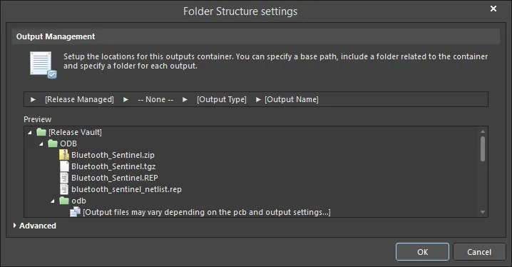
Options and Controls of the Folder Structure Settings Dialog
Output Management
Use this region to setup the location for this output container. You can specify a base path, include a folder related to the container, and specify the container's file name.
-
Release Managed - click to open a pop-up in which you can specify folder management.
-
Release Managed - select to make the file available to the PCB release system.
-
Manually Managed - select to set the file to be manually managed and stored in a local folder. By default, this will be a path specified in the Output Path field on the Options tab of the Project Options dialog.
-
File Location textbox - click the folder icon to browse to a target folder for the file. This option is available only when Manually Managed is selected.
-
Use relative path - enable this option to use a relative path in the File Location textbox. This option is available only when Manually Managed is selected.
-
Done - click to complete the configuration.
-
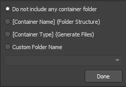
None - click to open a pop-up in which you can configure the container folder.
-
Do not include any container folder - select to not include a container folder.
-
[Container Name] (Folder Structure) - select to use Folder Structure as the folder name.
-
[Container Type] (Generated Files) - select to use Generated Files as the folder type.
-
Custom Folder Name - select to customize the folder name. Click the drop-down arrow to open a list from where you can choose a naming string for the folder. You also can directly enter the folder name in the textbox.
-
Done - click to complete the configuration.
-
Output Type - click to open a pop-up to configure the output folder.

-
Do not include any output folder - select to not include an output folder.
-
Output Name - select to use the output name as the output folder name.
-
Output Type - select to use the output type.
-
Custom prefix_[Output Type] - select to specify a custom prefix in the textbox.
-
Custom Folder Name - select to customize the folder name. Click the drop-down arrow to open a list from where you can choose a naming string. You also can directly enter the custom name in the textbox.
-
Done - click to complete the configuration.
-
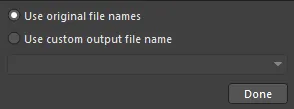
Output Name - click to open a pop-up in which you can configure the output file name.
-
Use standard output file name - select to use a standard output file name.
-
Use custom output file name - select to use a custom output file name. Click the drop-down arrow to open a list from where you can choose a naming string. You also can directly enter the custom name in the textbox.
-
Done - click to complete the configuration.
-
Preview - this region shows a preview of the folder structure. As changes are made in the above pop-up dialogs, the preview window is updated so you can immediately see how your changes affect the folder structure.
Advanced Version Commands
Output Options
-
Open generated outputs - enable to open the outputs after generation.
-
Add generated files to project - enable to add the generated files to your project. The files will appear in the Projects panel panel under the Generated sub-folder.
-
Use the Output Name as the file name instead of the default - enable to use the specified output name rather than a default name.
-
Timestamp folder - enable to create a timestamp folder. The date and time will be in the same format as your system settings.
CAMtastic Auto-Load Options
Enable the following output types if you want to auto-load the related outputs into CAMtastic. The enabled output types will be auto-loaded into a new CAMtastic document whenever a batch generation is performed.
-
ODB++ Output
-
Gerber Output
-
NC Drill Output
-
IPC-356-D Output
Once the above options are defined, they will persist. This means that the next time you run the Output Generators, the resulting output would be loaded into another new CAM Editor document. If you want to be able to update only the existing CAM document, enable the
Reset auto-load options after generation option. This results in the clearance (disabling) of all auto-load options after the initial generation. You can then gain access to the CAM Editor's
Rescan and
Reload commands (in the
CAMtastic panel, which is available whenever a
*.Cam document is active) that perform time-stamp comparison of generated and existing (imported) files and loading of data into existing layers.
-
Reset auto-load option after generation - enable to reset the auto-load option after generation of outputs.
Advanced/Basic
Click to toggle between the Advanced and Basic versions of the dialog.
-
For a Video output container, the Video Settings dialog will appear.

The Advanced and Basic versions of the Video settings dialog
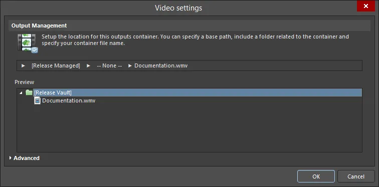
Options and Controls of the Video Settings Dialog
Output Management
Use this region to setup the location for this output container. You can specify a base path; include a folder related to the container then specify the container's file name.
-
Release Managed - click to open a pop-up in which you can specify folder management.
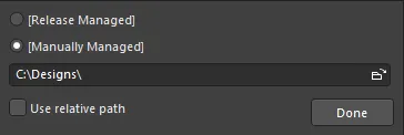
-
Release Managed - select to make the video available to the PCB release system.
-
Manually Managed - select to set the video to be manually managed and stored in a local folder. By default, this will be a path specified in the Output Path field on the Options tab of the Project Options dialog.
-
File location field - click the browse icon to browse for a target folder for the video. This option is available only when Manually Managed is selected.
-
Use relative path - enable this option to use a relative path in the File Location textbox. This option is available only when Manually Managed is selected.
-
Done - click to complete the configuration.
-
None - click to open a pop-up in which you can configure the container folder.
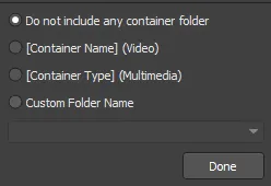
-
Do not include any container folder - select to not include a container folder.
-
[Container Name] (Video) - select to use Video as the folder name.
-
[Container Type] (Multimedia) - select to use Multimedia as the folder type.
-
Custom Folder Name - select to customize the folder name. Click the drop-down arrow to open a list from where you can choose a naming string for the folder. You also can directly enter the folder name in the text box.
-
Done - click to complete the configuration.
-
Output Type - click to open a pop-up to configure the output folder.
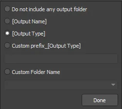
-
Do not include any output folder - select to not include an output folder.
-
Output Name - select to use the output name as the output folder name.
-
Output Type - select to use the output type.
-
Custom prefix_[Output Type] - select this option to specify a custom prefix in the text box.
-
Custom Folder Name - select to customize the folder name. Click the drop-down arrow to open a list from where you can choose a naming string. You also can directly enter the custom name in the text box.
-
Done - click to complete the configuration.
-
Separate file for each output - click to open a pop-up to specify how the output files are configured.
-
Separate file for each output using output name - select to create a separate file using the specified output name for each video.
-
Separate file for each output using custom name - select to create a separate file using a custom name for each video. Click the drop-down arrow to open a list from where you can choose a naming string. You can also directly enter the custom name in the text box.
-
Collate outputs into a single file - select to merge outputs into a single file. Click the drop-down arrow to open a list from where you can choose a naming string for the file. You can also directly enter the file name in the text box.
-
Done - click to complete the configuration.
Preview - this region shows a preview of the folders. As changes are made in the above pop-up dialogs, the preview window is updated so you can immediately see how your changes affect the folder structure.
Advanced Version Commands
Media Settings
-
Type - choose a media type from the drop-down list:
-
Video (FFmpeg)
-
Video (Windows Multimedia)
-
Video (Windows Media Format)
For all video types/formats, the exported video will be generated using a default frame rate of 25 frames per second. For Windows Multimedia video, the default pixel format used will be 32. For FFmpeg video (all formats), pixel format is uneditable and set to Planar YUV 4:2:0, 12bpp, (1 Cr & Cb sample per 2x2 Y samples). Windows Media formatted video has no pixel format defined.
The following table summarizes the video types and formats currently supported:
Video Type
|
Supported File Format(s)
|
Video (FFmpeg)
|
3GP2 (*.3g2)
ASF (*.asf, *.wmv, *.wma)
ASF-Streaming (*.asf, *.wmv, *.wma)
AVI (*.avi)
Flash (*.swf)
FLV (*.flv)
MOV (*.mov)
MP4 (*.mp4)
|
Video (Windows Multimedia)
|
Windows Video file (*.avi)
|
Video (Windows Media Format)
|
Windows Media file (*.wmv, *.wma, *.asf)
|
-
Format - choose a media format from the drop-down list. This option is available only when Video (FFmpeg) is selected as Type.
-
Video Pixels - use the up and down arrows (or enter numbers directly in the text boxes) to select the desired video pixels.
Output Options
-
Open after export - enable this option to open the video after exporting.
-
Prompt if file already exists - enable this option to see a prompt if the file already exists.
Advanced Settings
-
Video Codec - choose an option from the drop-down. This option is available only when Video (FFmpeg) or Video (Windows Media Format) are selected as Type. The following table summarizes the available Codecs based on the chosen video type/format.
Video Type/Format
|
Supported Codecs
|
FFmpeg / 3GP2
|
H.263 / H.263-1996
|
FFmpeg / ASF
|
MPEG-4 part 2 Microsoft variant version 2
MPEG-4 part 2 Microsoft variant version 3
raw video
Windows Media Video 7
Windows Media Video 8
|
FFmpeg / ASF-Streaming
|
MPEG-4 part 2 Microsoft variant version 2
MPEG-4 part 2 Microsoft variant version 3
raw video
Windows Media Video 7
Windows Media Video 8
|
FFmpeg / AVI
|
MPEG-4 part 2
MPEG-4 part 2 Microsoft variant version 2
raw video
|
FFmpeg / Flash
|
Flash Video (FLV) / Sorenson Spark / Sorenson H.263
|
FFmpeg / FLV
|
Flash Video (FLV) / Sorenson Spark / Sorenson H.263
|
FFmpeg / MOV
|
MPEG-4 part 2
|
FFmpeg / MP4
|
MPEG-4 part 2
|
Windows Multimedia
|
cvid Cinepak Codec
MSVC MS-CRAM
tscc TSCC
|
Windows Media
|
Windows Media Video V7
Windows Media Video 9 Screen
Windows Media Video 9
Windows Media Video V8
Windows Media Video 9 Advanced Profile
|
-
Compression - choose a desired compression setting from the drop-down list. This option is available only when Video (Windows Multimedia) is selected as Type.
-
Pixel Format - use the drop-down to select the desired pixel format for the video. This option is available only when Video (Windows Multimedia) is selected as Type.
-
Frames Per Second - enter the desired number of frames per second for the video. The default value is 25.
-
Quality - use the slider to specify the quality of the video, from lowest to highest.
Advanced/Basic
Click to toggle between the Advanced and Basic versions of the dialog.
Access to the Settings dialog can also be made by:
-
double-clicking the container entry;
-
selecting the container entry, right-clicking then choosing the Properties command;
-
selecting the container entry and choosing the Tools » Container Setup command from the main menus;
-
selecting the container entry and using the Ctrl+Shift+O shortcut.
The Settings dialog initially opens in Basic mode for configuration of the output location, i.e. where the container will be created. To access further, more advanced options related to the generation of output into the container, click the Advanced button at the bottom of the dialog.

Access the Settings dialog for the container to configure it as required. In Basic mode, use the dialog to define the output location for the container.

More detailed options are available with the dialog in Advanced mode.
An Output Container can be renamed - click once to select the output container, pause, then click a second time to edit the name.
Output Location
The output location – where the container will be created – is specified in the Output Management region of the container's settings dialog. The location consists of various stages with each stage defined using a corresponding pop-up accessed by clicking on that stage.
-
Base Path – this stage is used to define the 'root' path of the output container.

Options for defining the base path of the output location.
By default, this is set to [Release Managed], which means that the Board Design Release process, which is performed in the Project Releaser, will handle the base path automatically.
A local output path can be defined by switching this stage to [Manually Managed] and specifying the path accordingly (which can be made relative to the design project).
-
Container Type Folder – this stage is used to define a sub-folder based on the type of media container being generated. It is completely optional as to whether this extra 'umbrella' folder is used or not. If used, it can either be named by the system (using the container name or type) or you can give it a custom name if required.

Options to define a container sub-folder for the output location.
-
Output Folder / Output Filename – the function of this stage depends on the output container type for which the output location is being specified. For PDF or Video container types, this stage requires entry of the desired filename. By default, multiple outputs generated into the container will be collated into a single file, but you have the option to generate a separate file for each output if required.
If generating a separate file per output, the additional option to place each file in its own sub-folder becomes available. If enabled, the folder can be named automatically based on the output name or type or can be customized with a specific prefix.

Options to define filename and optional sub-folder.
For the Folder Structure container type, this stage is used to specify a folder for each generated output type. Again, the folder can be named automatically based on the output name or type or can be customized with a specific prefix. As changes are made to any of the stages in the output location, the preview window of the dialog will dynamically update, allowing you to quickly zero-in on a preferred output folder structure. For each defined container, the paths – both server-based (Release Managed) and local (Manually Managed) – are displayed for quick reference in the main Output Containers region of the OutJob.
Rules for Concatenating Elements
The user-defined output name is built up by concatenating (joining together) the required elements. The concatenation process obeys the following rules:
| Element |
Function |
Example |
Returns |
| = (equals) |
Indicates that the following string is an expression that must be interpreted. |
=ProjectName |
DB31 for the example project named DB31.PrjPcb |
| + (plus) |
Used to concatenate the elements required in the output name. |
=ProjectName + '-' + ProjectRevision + '.PDF' |
DB31-07.PDF for the example project named DB31.PrjPcb |
| ' ' (single quotes) |
Used to include a fixed string anywhere within the output name. Illegal characters are listed below. |
='AcmeEngineering' +_+ ProjectName + '.PDF' |
AcmeEngineering_DB31.PDF for the example project named DB31.PrjPcb |
Illegal Characters and Syntax Errors
The following characters are not permitted in user-defined output names:
< > : " \ | ? *
If there is a syntax error in an expression, for example, an unbalanced quote such as =ProjectName+.PDF' instead of =ProjectName+'.PDF', this will give the result #NAME. When you see this, look carefully for missing quotes or invalid or mistyped special strings.
Supported Parameters
User-defined Project-level parameters and variant parameters are supported. Project parameters are defined on the Parameters tab of the Project Options dialog (Project » Project Options). Variant parameters can be defined for each variant in the Variant Management dialog or the Variant Manager (Project » Variants).
Parameter names cannot include spaces. For example, the parameter PartNumber can be used, however, the parameter Part Number can not.
Supported Special Strings
Special Strings is the term used in Altium Designer to define interpreted strings. Most of these strings can be interpreted on screen by placing a text string with a value of =SpecialStringName, for example =CurrentDate. They are always interpreted during output generation.
Currently supported Special Strings that can be used in Output filenames include:
| Special String |
Returns |
| CurrentDate |
The current date, as retrieved from the Operating System, in the ISO 8601 format yyyy-mm-dd. Example: 2016-01-25 |
| CurrentTime |
The current time, as retrieved from the Operating System, in the format hh_mm. Example: 14_55. |
| DataSource |
The Data Source used for this Output in the Output Job file. |
| OutputName |
The user-defined name of this Output in the Output Job file. Only functions when the Separate File for Each Output option is selected in the Output file naming settings. |
| ProjectName |
Displays the actual name of the project, excluding the extension. |
| VariantName |
The name of an assembly variant defined for this project in the Variant Management dialog or the Variant Manager. The value used depends on the Variant chosen in the Output Job for the Output whose filename is being defined. |
| ProjectParameterName |
The value of the Project Parameter named <ProjectParameterName>. |
| VariantParameterName |
The value of the Variant Parameter named <VariantParameterName>. |
Naming Collated Output Files
For collated output files, only those special strings that are not restricted to a specific output can be used. For example, OutputName cannot be used for a collated output file as it applies to a specific output in the Output Job file. VariantName and DataSource also cannot be used. Use of one of these special strings in a collated output file will result in the actual string being used as the filename.
If the expression fails to be analyzed, save then close and reopen the Output Job file to refresh the expression analysis engine.
Hard Copy - Print Jobs
Certain outputs, including Schematic Prints, Assembly Drawings and BOM, can also be sent directly to a printing device as Hard Copy. To determine how such hard copy is handled, a Print Job is added and configured.
A new OutJob will default to include a single Print Job named Print Job and target the default printer associated with the computer upon which the instance of Altium Designer is running. Any number of additional Print Jobs can be added by clicking the [Add New Print Job] text or from the Edit » Add Print Job sub-menu, and their names can be edited for easy identification (e.g. the name of the printing device to which the job is associated).

Print jobs handle print-based output or "Hard Copy."
Configuring a Print Job
Clicking on a Print Job provides access to additional controls including the ability to configure the job. To do so, click the Change link to access the Printer Configuration dialog associated with that particular job. Access to the Printer Configuration dialog can also be made by either double-clicking the Print Job entry or selecting it, right-clicking then choosing the Properties command.

Access the Printer Configuration dialog to configure the Print Job as required.
In the Printer Configuration dialog, click the Properties button to access the standard Properties dialog for the target printer. In this dialog, define the paper source and layout and gain access to advanced property settings for the printer.
Linking Outputs to Output Containers and Print Jobs
With the outputs of the OutJob added and configured, and the required Output Containers and Print Jobs defined, they now need to be mapped, i.e. specify which outputs are to be generated using which container and/or print job.
Each output has an associated Enabled field. This field provides control over whether or not a particular output is included (option enabled) or excluded (option disabled) from a selected Output Container or Print Job.
The Enabled field is only available provided the output is supported for generation into the selected container or for printing to the selected printing device.
You can also quickly enable/disable all selected outputs or all outputs in the focused category, connecting them to / disconnecting them from the currently selected output container, or print job, by right-clicking on an output in the selection or in the required category of outputs and choosing the Enable Selected (shortcut: Ctrl+Num +)/Disable Selected (shortcut: Ctrl+Num -), Enable All/Disable All command from the context menu.
Once enabled, a green line will connect an output to the selected container/print job. The same output can be included in many output media, for example, a BOM can be generated and output as a PDF, as a distinct file, or sent to a printer for an immediate hard copy.

Select the container or print job, then enable the outputs that are to be generated using that container or print job.
In the image above, three outputs have been enabled for generation using the PDF-based Output Container named PDF. Notice how Test Point Report, Pick and Place, and Gerber Files outputs do not have an Enabled field since those output types cannot be written to a PDF file.
As outputs are enabled, they are numbered consecutively. This ordering is used to define the sequence in which the outputs are generated. If creating a single PDF including multiple different outputs, this order determines the sequential content of those outputs with that PDF.
If an output is removed from a container or print job, the numbers are re-ordered accordingly. To change the order of enabled outputs, either double-click on the number in the Enabled field of an output and use the available control to change the required number or re-select each output in order.
When using Enable Selected/Disable Selected, Enable All/Disable All commands, it can be a good idea to sort that order first, since the output generation sequence is assigned by the order of the outputs. This can be achieved quickly and efficently by clicking on an output, and dragging it to a new location within its category.
Why is my Output to Container Link Red?
When the target for an applicable print-based output is changed from a PDF output container to a physical printer (print job), it is quite possible that the paper size defined for the generator - through the relevant properties dialog (right-click, Page Setup) - may not be supported by the target medium. In this case, the connecting arrow from generator to medium is colored red when the output is enabled. You will be prevented from previewing/printing in this state. You can either change the paper size for the output generator, and thus return the connecting arrow to a green state, before the applicable output can be successfully generated. Or, simply change the target medium to one that does support your chosen paper size. Where a paper size mismatch exists, and you opt to change the paper size for the configured output, using the Page Setup command for the output will bring up an information dialog. This alerts you to the issue and notifies you that the paper sizing has been restored to its default. What this means is that the paper size drop-down in the configurator dialog is loaded afresh with the standard set of paper sizes supported by the target printer.

A red link indicates a mismatch between the page setup and the page properties available in the chosen container.
Variant Choice
Product requirements may warrant the need to produce a variety of similar Printed Circuit Boards that all differ slightly from an underlying base design. For example, standard and deluxe versions of a commercial electronic product may differ in the functionality they offer, with the standard version incorporating a subset of the components used in the deluxe version.
At the design level, Altium Designer enables one or more variations of a board design to be defined using its Variants feature. A variant is simply an alternately assembled 'version' of the original board design.
Variants typically drive applicable assembly-based outputs – the very essence of an Assembly Variant, varying only the assembled board (e.g., which components are fitted or not). However, Altium Designer also enables variants to drive certain fabrication outputs, allowing a comment for a component to be varied in a design and that change can be fed through to outputs such as Gerbers, ODB++ files, Composite Drill Drawings, Drill Drawing/Guides, and Final Artwork Prints.
Although it is fabrication outputs that can be driven, it is only changing such output based on the component-level variations for the target board assembly – in this case, the component's Comment parameter. No other aspect of the fabricated board (the physicalities of the PCB) can be changed, such as the routing, the layout of the components, or the layer stack.
From within an OutJob, you have full control over what is used to drive the defined outputs – either the base (non-varied) design or a nominated defined variant of that design.
If the outputs are to be generated for a specific variant, then that variant must be specified as part of the configuration of the OutJob. Either choose a variant per applicable output or choose a single variant to apply to all applicable outputs in the file. This 'variant scope' is determined using the Variant Choice options at the top of an Output Job file.

Variant Choice options determine at which level variants are used when driving the configured outputs of an Output Job file.
-
Choose a single variant for the whole outputjob file – with this option enabled, choose a single variant to drive all applicable outputs in the Output Job file. Specify the variant in the drop-down field to the right. The drop-down lists all defined variants for the active project as well as the entry
[No Variations].
-
Choose a different variant for each output – with this option enabled, a Variant column will be added to the Outputs region of the OutJob. Use this field to indicate which variant to use on an individual output basis. Again, the drop-down lists all defined variants for the active project, as well as the entry
[No Variations]. Using this scope setting it is possible to assign different variants to drive different outputs.
To drive the outputs using the base (non-varied) design, use the [No Variations] entry.
When defining variant usage at the individual output level, if the chosen variant does not allow the variation of fabrication outputs and the variant is specified for use with a fabrication-based output, the variant entry in the OutJob will be red, and a hover-tip used to flag the situation. Generation of output using the chosen variant will proceed as though the setting [No Variations] had been chosen. In other words, the base (non-varied) design will be used as the source of the output instead.
Output Generation
The configured outputs in an OutJob can be generated either:
From Output Containers
Selecting an Output Container provides access to the Generate content control. This control is enabled after at least one output is assigned to that container.

Generate content for the selected Output Container.
Click this control to generate each output enabled for generation into the container in sequence. Alternatively, with the container selected, use one of the following methods to generate content:
-
Press the F9 key.
-
Right-click then choose the Generate command from the context menu (Run command for a Folder Structure container).
-
Use the Tools » Generate command (PDF and Video container types) or the Tools » Run command (Folder Structure container type).
-
Click the
 (PDF container type),
  (Video container type) or
  (Folder Structure container type) button on the Job Manager Toolbar toolbar.
Progress can be viewed from the Status Bar. Generated output will be written to the location defined as part of the settings for the output container. These settings will also control whether the output is opened and/or added to the Projects panel. Generated output will be opened if the option to do so has been enabled as part of the advanced options for the container.
There is no multiple Output Container batch generation process; only those outputs assigned to the currently selected Output Container will be generated. To generate all outputs, select and generate content for each defined Output Container, separately.
When generating Gerber, ODB++, NC Drill, or IPC-356-D outputs into a Folder Structure Output Container, they can be imported automatically into a new CAM Editor document (*.cam). Options to do this can be found in the Files Settings dialog associated with the container type.
To open an existing PDF document that has been generated through a defined PDF output container in the active Output Job Configuration file, right-click on the required PDF output container (in the Output Containers region) then choose the Open PDF command from the context menu. The command is available only after the PDF has been generated and while the Output Job Configuration file remains open.
Note that if the Output Job Configuration file is closed and then reopened, the command will no longer be available even though the PDF exists. You will either need to generate the file again or browse for the file in the location in which it was created.
Publishing Generated Content
A second control – Generate and publish – enables you to generate the outputs assigned to the selected Output Container and also publish that output to a defined Publishing Destination.
Publishing Destinations offer the ability to publish data to a storage space, such as Box.net, Amazon S3, an FTP server, or a folder location on a shared network. In terms of distribution and collaboration, this provides an unparalleled advantage in today's world where the collective members of the overall 'product team' – the design team, the manufacturing team and all others involved in the process of getting a product from thought to reality – are often dispersed around the globe. All parties have shared (and controlled) access to view, discuss and utilize the data.
To publish, click the command then select from a list of currently defined destinations in the pop-up menu that appears. The output will be generated first to the local path destination, then published. As part of publishing, a prompt will appear asking for a folder (within the target Publishing Destination) in which to store the output. Either browse to an existing folder, specify a new folder, or accept the default folder – named using the type of content for the container, along with a date-time stamp (e.g., PDFs - 10-24-2011 11-32-33 AM).
Use the Manage Publishing command on the menu to access the Data Management – Publishing Destinations page of the Preferences dialog. From here, new destinations can be defined or the connections to existing destinations can be modified.

Publishing Destinations are specified as part of the Data Management preferences.
For released data generated from a board design project, a server supports the ability to publish those released documents i.e. generated output from Output Job files assigned to the released project configuration, for any Item Revision to a defined Publishing Destination.
Publishing data directly from an OutJob places a copy of the generated files in a specified sub-folder of the target destination. For high integrity and to facilitate a solid audit trail, generated data should be published after release into a revision of a target item in a server. Such output is tagged (in the filename) with the Item and Revision, enabling all involved to see instantly which output is associated with which revision of the item to be built (bare board or assembled board).
From Print Jobs
Selecting a Print Job will provide access to Preview and Print controls. These controls will be enabled provided at least one output is assigned to that job.

Preview and Print controls for the selected Print Job.
Print Preview
Click Preview to load the assigned outputs for the Print Job into the print preview. Alternatively, with the job selected, use one of the following methods to access the print preview:
-
Right-click then choose Print Preview from the context menu.
-
Use the Tools » Print Preview command.
-
Clicking the
 button on the Job Manager Toolbar toolbar.
-
Click the Preview button in the Page Setup dialog (File » Page Setup) for the selected (focused) output. Note that this will load only the pages for that particular output and not all pages for all assigned outputs to the Print Job.
Source documents will be loaded in sequence and in accordance with options defined in the associated Page Setup dialog.
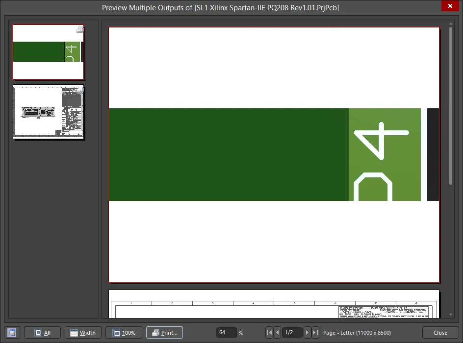
Controls are provided at the bottom of the Report Preview and on its right-click menu for manipulating the view, accessing printer setup dialogs, printing, copying a page to the Windows clipboard, and exporting the active page as a Windows Metafile.
Printing
Click Print to send the output(s) directly to the nominated printing device. Alternatively, assigned output(s) can be printed using one of the following methods:
-
Press the F9 key.
-
Right-click then choose the Print command from the context menu.
-
Use the Tools » Print command.
-
Click the Print button in the Page Setup dialog for the selected (focused) output. Note that this will print only the pages for that particular output and not all pages for all assigned outputs to the Print Job.
-
Clicking the Print button in the Print Preview dialog.
-
Clicking the
 button on the Job Manager Toolbar toolbar.
The Print control and the first three methods listed above offer direct printing. The last two methods above are indirect printing via the Printer Configuration dialog.
There is no multiple Print Job batch print process; only those outputs assigned to the currently selected Print Job will be previewed/printed. To print all outputs, select and print for each defined print job separately.
From the Project Releaser
Outputs defined in one or more Output Job files assigned to a configuration of a PCB project are generated when that configuration is released. This generation happens as part of the high integrity release process with the release data stored in a new, planned revision of a target Item in a server. The Project Releaser is the interface used for this to happen.
The Project Releaser can be accessed in the following ways:
-
Choose the Project » Project Releaser command from the main menus (with a source document for the required project open as the active document).
-
Right-click on the entry for the required project in the Projects panel, then choose the Project Releaser command from the context menu.
If Outputs have not been defined before running the Project Releaser, this can be done as part of the release process instead.
For the Fabrication and Assembly data items to be included in a release, at least one OutputJob file is required to be assigned to them. If you have Output Job files with names that start with the sub-strings 'fab' and 'ass', those OutJobs will be assigned automatically to the Fabrication Data and Assembly Data sections, respectively, when the Release view is first accessed. If not, you will need to assign the applicable OutJobs in each case manually.

Example list of outputs to be generated for a chosen configuration.
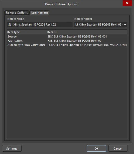
From the Project Releaser, click the Options button (lower left-hand corner) to open the Project Release Options dialog. This dialog is used to assign the applicable OutJobs and define how the target data items in a server (whose revisions receive the generated data) are named when releasing a project. The Release Options tab includes several options under the Output Jobs region for enabling desired output data.

The Release Options tab of the Project Release Options dialog.
If your project currently has no Output Job file(s) associated with it, the Project Releaser will detect this and you will be asked if you want to add default ones. If you opt to do so, the following will be created:
-
Fabrication.OutJob - with the following outputs defined:
-
Documentation Outputs: PCB Prints
-
Fabrication Outputs: Gerber, NC Drill, and IPC-2581
-
Validation Outputs: Design Rules Check, Footprint Comparison Report
-
Export Outputs: Save As/Export PCB (in ASCII format)
-
Assembly.OutJob - with the following outputs defined:
-
Documentation Outputs: PCB 3D Print, Schematic Prints, Composite Drawing
-
Assembly Outputs: Pick and Place Report, Assembly Drawings, Test Point Report
-
Report Outputs: Bill of Materials, Component Cross Reference, GOST BOM
To access GOST BOM output in Altium Designer, the GOST 2.701-2008/2.106-1996 software extension must be installed. This extension can be installed or removed manually.
For more information about managing extensions, refer to the Extending Your Installation page (Altium Designer Develop, Altium Designer Agile, Altium Designer).
-
Export Outputs: Export STEP
If you have at least one OutJob file defined for the project, this auto-creation will not be offered.
For more information about the release process, visit the Design Project Release page.

