
Additional Views
除了 板装配视图 和 板制造视图 之外,Draftsman 还建议使用若干额外的自动化设计视图来完善你的 PCB 图纸。
板剖视图
Draftsman 的板剖视图会提供一张轮廓切片(剖面)图:从已放置的 板装配视图 中指定的“切割”位置取一条剖切线生成。剖视图生成器会利用当前 PCB 的可用 3D 数据,创建一张与所指定切割位置对齐的独立剖面图。

在板装配视图上应用的两个已放置板剖视图
创建板剖视图的步骤如下:
-
选择板剖视图放置命令(Place » Additional Views » Board Section View)。
-
将光标移动到板装配视图上,此时会出现一条随光标移动的垂直剖切线。使用
Spacebar在垂直与水平剖切线之间切换。 -
单击以设置剖切线的位置。
-
将光标移动到剖切线任一侧以设置视图方向(由剖切线箭头指示),然后单击确认。
-
拖动并将新的板剖视图放置到所需位置。
当已放置的板剖视图在设计空间中被选中时,可通过图形方式修改其位置、大小和目标点。该视图支持多种图形编辑模式:
-
Click, Hold&Drag拖动板剖视图图形以改变其位置。 -
Click, Hold&Drag拖动板剖视图的缩放手柄(节点),位于其外框右上角,用于修改视图渲染尺寸。 -
Click, Hold&Drag拖动板剖视图的剖切线(避开其节点)以改变穿过电路板的切割位置。 -
Click, Hold&Drag拖动板剖视图剖切线的任一节点以改变穿过电路板的切割范围(端点)。 -
拖动剖切线或其节点时,使用
Spacebar来更改 Positioning Mode (Horizontal 或 Vertical)。
板剖视图放置与图形编辑演示
已放置板剖视图的绘图表现、视图方向与标注,可在设计空间中选中该视图时,通过 Properties 面板进行配置(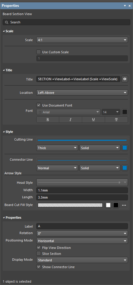 )。
)。
比例 |
|
| Scale, Use Custom Scale |
使用这些选项配置视图比例。更多信息请参阅 使用视图 页面。 |
标题 |
|
| Title, Location, Font |
使用这些选项配置视图标题。更多信息请参阅 使用视图 页面。 |
样式 |
|
| Cutting Line | 使用下拉框选择用于渲染视图带箭头指示线的线宽与线型。可用选项在设计空间未选中任何对象时,于 Line Styles 面板的 Properties 区域中定义。更多信息请参阅 设置 Draftsman 文档 页面。 使用相应的颜色按钮指定线条颜色。 |
| Connector Line | 使用下拉框选择用于渲染视图剖切线的线宽与线型。剖切线位于带箭头的剖面指示符之间(并穿过板装配视图)。可用选项在设计空间未选中任何对象时,于 Line Styles 面板的 Properties 区域中定义。更多信息请参阅 设置 Draftsman 文档 页面。 使用相应的颜色按钮指定线条颜色。 |
| Arrow Style | 使用所提供的选项配置剖面指示符。
|
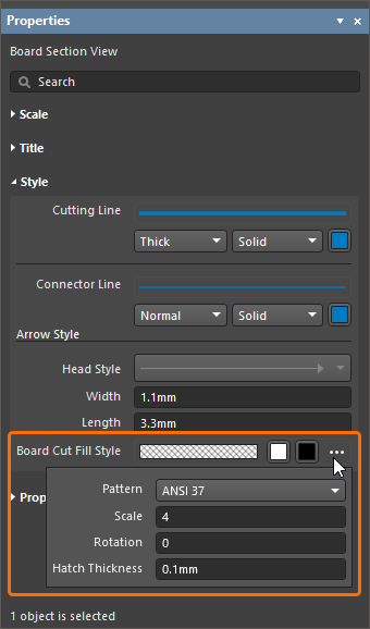
| Board Cut Fill Style | 使用这些选项配置被剖切(切开)的电路板的图形填充图案与颜色显示。图案色块会根据当前配置预览图案效果。使用相应的颜色按钮为填充与剖面线(hatch)图案指定颜色。选择相应的
|
属性 |
|
| Label | 用于视图标签名称的文本字符串/字符,会显示为剖切标签。 |
| Rotation | 板剖视图相对于源板装配视图的渲染旋转角度。使用下拉菜单从一系列 90° 预设值中选择。 |
| Positioning Mode | 剖切的 X/Y 方向,Horizontal 或 Vertical。 |
| Flip View Direction | 启用后,剖视图的方向(观察方向)会反转,剖切线方向箭头也会相应改变。 |
| Slice Section | 启用后,将禁用剖切线后方对象的可见性。它会从视图中移除背景对象,从而创建一个真正意义上的穿板剖切视图( )。 )。 |
| Display Mode | 剖切指示箭头的显示样式,使其定位在剖切线之后(Standard)或之前(Alternative)( )。 )。 |
| Show Connector Line | 启用后,将显示剖切线。 |
 ):
):
板细节视图
Draftsman 的板细节视图功能允许将图纸中定义的区域提取出来,生成一个悬浮的放大细节视图。板细节视图可添加到 板装配视图、板制造视图、板剖视图、元件视图、钻孔图视图、板等轴测视图 以及 板区域视图。板细节视图可使用圆形或矩形形状创建。
")
在板装配视图与板制造视图上应用的两个已放置板细节视图(位于底部)
创建板细节视图的步骤如下:
-
选择板细节视图放置命令(Place » Additional Views » Board Detail View » Circle area detail view 或 Place » Additional Views » Board Detail View » Rectangle area detail view,取决于所需的视图形状)。
-
在图纸上的某一点(在受支持的视图上)单击,以指定目标板细节视图区域的中心点。
-
移动鼠标后单击,以指定视图区域(板细节视图源)的半径(圆形视图)/角点(矩形视图)。视图会以悬浮方式跟随光标显示。
-
再次单击以设置板细节视图放大图的位置。
板细节视图及其源区域/尺寸都可进行图形化修改。要启用其图形编辑模式,请单击图形表示的任意部分,包括板细节视图放大图、源区域边界、标签或连接/引线。
-
Click, Hold&Drag拖动板细节视图本体(源区域的放大视图)以改变其位置。 -
将光标悬停在标签或连接/引线上(光标会变为“移动”十字 –
 ),然后
),然后 Click, Hold&Drag以移动视图源区域的位置。 -
将光标悬停在源区域轮廓上(光标会变为“调整大小”十字 –
 ),然后
),然后 Click, Hold&Drag以改变视图源区域的大小。 -
如果板细节视图对象使用标签引线(在 Properties 面板中将 Display Mode 设置为 With Leader),它将显示一个可编辑手柄,可拖动该手柄以重新定位引线及其标签。
板细节视图放置与图形化编辑演示
已放置的板细节视图的放大倍率(比例)、标注以及线条属性,可在设计空间中选中该视图(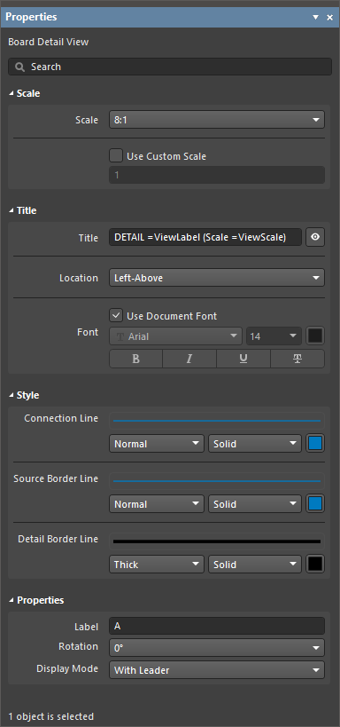 )后,在 Properties 面板中进行配置。
比例 |
|
| Scale, Use Custom Scale |
使用这些选项来配置视图的比例。更多信息请参阅 Working with Views 页面。 |
标题 |
|
| Title, Location, Font |
使用这些选项来配置视图的标题。更多信息请参阅 Working with Views 页面。 |
样式 |
|
| Connection Line | 使用下拉列表选择用于绘制引线标签线(当 Display Line 选项设置为 With Leader 时)或连接源轮廓与视图本体的连线(当 Display Line 选项设置为 Connected 时)的线宽与线型。可用选项在设计空间未选中任何对象时,于 Properties 面板的 Line Styles 区域中定义。更多信息请参阅 Setting Up a Draftsman Document 页面。 使用关联的颜色按钮指定线条颜色。 |
| Source Border Line | 使用下拉列表选择用于绘制视图源区域轮廓的线宽与线型。可用选项在设计空间未选中任何对象时,于 Properties 面板的 Line Styles 区域中定义。更多信息请参阅 Setting Up a Draftsman Document 页面。 使用关联的颜色按钮指定线条颜色。 |
| Detail Border Line | 使用下拉列表选择用于绘制视图放大区域轮廓的线宽与线型。可用选项在设计空间未选中任何对象时,于 Properties 面板的 Line Styles 区域中定义。更多信息请参阅 Setting Up a Draftsman Document 页面。 使用关联的颜色按钮指定该线条的颜色。 |
属性 |
|
| Label | 用于视图标签名称的文本字符串/字符。当 Display Line 选项设置为 With Leader 或 No Leader 时,它将显示为视图标签。 |
| Rotation | 显示放大区域的角度,其中 0° 与源(目标)绘图视图中该区域固有的视图角度相关。可在下拉菜单中从一系列 90° 视图选项中选择。 |
| Display Mode | 视图源的连接线样式。使用下拉列表选择 Connected、With Leader 或 No Leader 样式( )。 )。 |
元件视图
Draftsman 元件视图(Place » Additional Views » Component View)是一个装配视图风格的绘图对象,用于显示当前板设计中的单个元件。 当设置为剖面视图时,渲染的元件视图将包含支撑 PCB 的相关剖面部分。

两个已放置的元件视图,分别从顶部和前侧显示同一元件
已放置的元件视图最初会显示 BOM 数据中登记的第一个元件。可在 Properties 面板的 Properties 区域中,通过 Component 下拉列表将其更改为所需元件;该区域还提供用于定义元件视图图形样式与视角(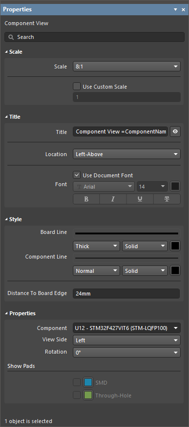 )的属性设置。
比例 |
|
| Scale, Use Custom Scale |
使用这些选项来配置视图的比例。更多信息请参阅 Working with Views 页面。 |
标题 |
|
| Title, Location, Font |
使用这些选项来配置视图的标题。更多信息请参阅 Working with Views 页面。 |
样式 |
|
| Board Line | 当 View Side 设置为非 Top 的值时,使用下拉列表选择用于绘制板线的线宽与线型。可用选项在设计空间未选中任何对象时,于 Properties 面板的 Line Styles 区域中定义。更多信息请参阅 Setting Up a Draftsman Document 页面。 使用关联的颜色按钮指定线条颜色。 |
| Component Line | 使用下拉列表选择用于绘制视图中元件几何图形的线宽与线型。可用选项在设计空间未选中任何对象时,于 Properties 面板的 Line Styles 区域中定义。更多信息请参阅 Setting Up a Draftsman Document 页面。 使用关联的颜色按钮指定线条颜色。 |
| Distance To Board Edge | 当 View Side 设置为非 Top 的值时,指定元件视图到板边缘的距离。 |
属性 |
|
| Component | 将在视图中渲染的板设计元件。使用下拉菜单从所有可用的元件位号列表中选择。 |
| View Side | 用于渲染元件图的视图方向。使用下拉菜单从一系列预设视图方向中选择。 |
| Rotation | 用于渲染视图的旋转角度,由下拉菜单应用。 |
| Show Pads | 仅当所选元件视图的 View Side 设置为 Top 时,此区域中的选项才可用。启用 SMD 和/或 Through-Hole 选项以在视图中渲染相应的焊盘形状。选择关联的颜色按钮以指定焊盘显示颜色。 |
 )。启用它们分别渲染键合线投影与 die pad。 选择关联的颜色按钮以指定对象显示颜色。
钻孔图视图
Draftsman 钻孔图视图(Place » Additional Views » Drill Drawing View)是对活动 PCB 项目的板外形与钻孔的自动图形合成。该视图使用可定义的符号进行渲染,这些符号对应不同的孔类型,并且还包含任何已指定的钻孔层对。

已放置的钻孔图视图可显示所有或特定钻孔层对的孔,并使用已定义的孔组符号进行渲染。
已放置的钻孔图视图初始会显示所有层的钻孔层对。放置后可按需更改,可通过 Properties 面板进行设置;该面板还提供用于定义钻孔图视图的观察面以及为各类钻孔分配的钻孔符号图形的属性设置(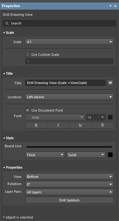 )。
)。
比例 |
|
| Scale, Use Custom Scale |
使用这些选项配置视图比例。更多信息请参阅 Working with Views 页面。 |
标题 |
|
| Title, Location, Font |
使用这些选项配置视图标题。更多信息请参阅 Working with Views 页面。 |
样式 |
|
| Board Line | 使用下拉列表选择用于渲染视图边框/外轮廓的线宽与线型。可用选项在设计空间未选中任何对象时,于 Properties 面板的 Line Styles 区域中定义。更多信息请参阅 Setting Up a Draftsman Document 页面。 使用关联的颜色按钮指定线条颜色。 |
属性 |
|
| View | 用于渲染视图的观察方向。使用下拉菜单指定 Top 或 Bottom 视图方向。 |
| Rotation | 用于渲染视图的旋转角度,由下拉菜单应用。 |
| Layer Pairs | 选择在绘图视图中显示哪些 PCB 钻孔层对的孔。使用下拉菜单从源板设计中可用的层对中选择;这些层对可在 PCB 编辑器的 Layer Stack Manager 中查看与编辑。所有板设计都会有一个 Top Layer 到 Bottom Layer 的层对,而其他层对则表示贯穿层间或通向其他层(例如内层/电源层)的过孔。更多信息请参阅 Blind, Buried & Micro Via Definition 页面。 |
| |
单击该按钮以打开 Drill Symbol Configurations 对话框,该对话框以表格形式显示所有钻孔数据,并可按可选参数(列数据)对孔样式分组并分配标准符号。该对话框允许为每种孔符号设置样式与尺寸。 |
板等轴测视图
Draftsman 板等轴测视图(Place » Additional Views » Board Isometric View)是对活动 PCB 项目板级装配的自动投影图形合成。

两个已放置的板等轴测视图;左侧为正面视图,右侧为顶面视图
已放置的板等轴测视图的设置(包括其面侧与设计变体)在设计空间中选中该视图时,可在 Properties 面板中进行设置(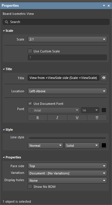 )。
)。
比例 |
|
| Scale, Use Custom Scale |
使用这些选项配置视图比例。更多信息请参阅 Working with Views 页面。 |
标题 |
|
| Title, Location, Font |
使用这些选项配置视图标题。更多信息请参阅 Working with Views 页面。 |
样式 |
|
| Line Style | 使用下拉列表选择用于渲染视图的板外形与元件几何图形的线宽与线型。可用选项在设计空间未选中任何对象时,于 Properties 面板的 Line Styles 区域中定义。更多信息请参阅 Setting Up a Draftsman Document 页面。 使用关联的颜色按钮指定线条颜色。 |
属性 |
|
| Face side | 用于渲染视图的等轴测投影方向。使用下拉菜单从一系列预设视图方向中选择。 |
| Variation | 该视图显示数据所对应的设计变体。对于所选变体中设置为不装配(not fitted)的元件,将不会在视图中渲染。 |
| Display holes | 使用下拉菜单选择所需的孔显示选项: None、 All 或 Pads only。 |
| Show No BOM | 使用此选项切换视图中不在 BOM 中的元件(其 Type 在 PCB 编辑器中设置为 Standard (No BOM))的显示。 |
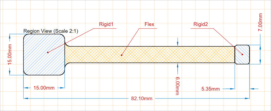
板区域视图
板区域视图(Place » Additional Views » Board Region View)允许 Draftsman 文档包含对板设计中多个叠层区域的精确表示,例如应用于 刚挠结合 PCB 设计 的那些区域。视图中使用的叠层命名与数据来自 PCB 设计,并由 PCB 编辑器的 Board Planning Mode 视图与 Layer Stack Manager 表示。

已放置的板区域视图
已放置的板区域视图的设置在设计空间中选中该视图时,可在 Properties 面板中进行设置(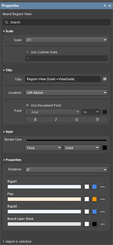 )。
)。
比例 |
|
| Scale, Use Custom Scale |
使用这些选项配置视图比例。更多信息请参阅 Working with Views 页面。 |
标题 |
|
| Title, Location, Font |
使用这些选项来配置视图的标题。更多信息请参阅 Working with Views 页面。 |
样式 |
|
| Border Style | 使用下拉列表选择用于绘制视图板框轮廓的线宽和线型。可用选项在设计空间未选中任何对象时,于 Line Styles 面板的 Properties 区域中定义。更多信息请参阅 Setting Up a Draftsman Document 页面。 使用对应的颜色按钮指定线条颜色。 |
属性 |
|
| Rotation | 通过下拉菜单应用的、用于渲染视图的旋转角度。 |
| 区域图形属性 | 针对电路板的每个层叠区域,都会包含一个条目,用于配置其对应的图形属性。图案色块会根据已配置的设置显示图案预览。使用对应的颜色按钮为填充和网纹图案指定颜色。选择对应的
|
 ):
):
电路板真实视图
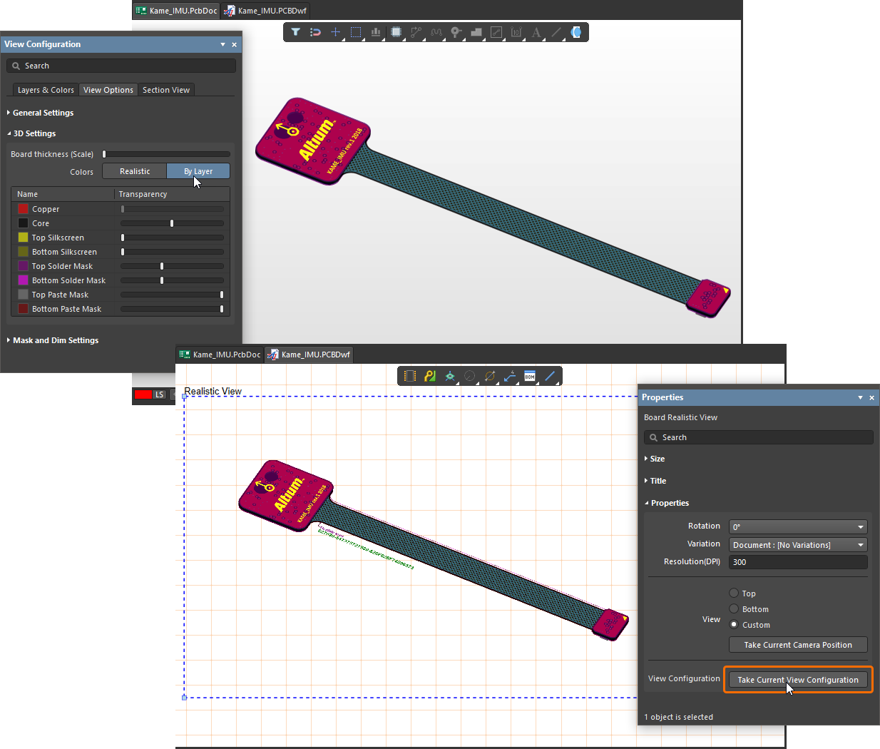
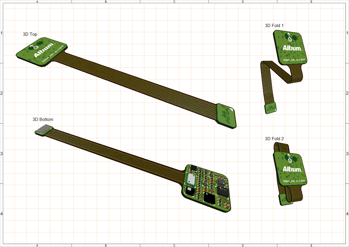
Draftsman 电路板真实视图(Place » Additional Views » Board Realistic View)在绘图文档中提供高层次的纯视觉信息,用于展示装配与制造数据。作为独立且可配置的视图对象放置后,电路板真实视图会提供当前板设计的可缩放 3D 渲染。该 3D 视图由软件的 3D 渲染引擎生成(与 PCB 编辑器中应用的相同 ),并可设置为采用 PCB 编辑器当前的视角与配置。

一个已放置的电路板真实视图。视角取自 PCB 编辑器。
当在设计空间中选中该视图时(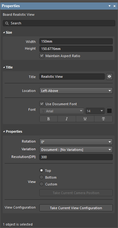 ),已放置的电路板真实视图的设置可在 Properties 面板中获取。
尺寸 |
|
| Width | 视图的宽度。 |
| Height | 视图的高度。 |
| Maintain Aspect Ratio | 启用此选项后,当通过输入新的 Width 或 Height ,或在设计空间中拖动对象的选择节点来缩放对象时,图像尺寸将保持比例不变。 |
标题 |
|
| Title, Location, Font |
使用这些选项来配置视图的标题。更多信息请参阅 Working with Views 页面。 |
属性 |
|
| Rotation | 通过下拉菜单应用的、用于渲染视图的旋转角度。 |
| Variation | 该视图显示其数据所对应的设计变体。对所选变体设置为不装配(not fitted)的元件不会在视图中渲染。 |
| Resolution(DPI) | 视图的质量(分辨率)。最低设置为 75 DPI。 |
| View | 选择 Top 或 Botton 以从源板设计的对应侧渲染视图,或选择 Custom 以启用 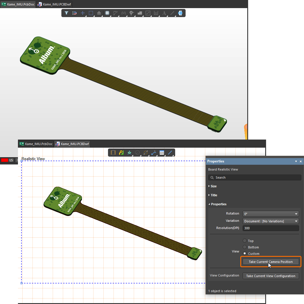 )。 )。 |
| View Configuration | 单击 |
 )中定义。
)中定义。
沉孔视图
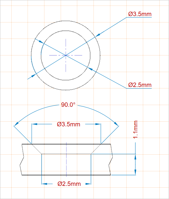
Draftsman 沉孔视图(Place » Additional Views » Counter Hole View)用于表示带有沉孔特征(沉孔 counterbore 和/或 沉头 countersink)的电路板焊盘孔。当设置为剖面视图时,渲染的沉孔视图会包含 PCB 的对应剖面截面。

两个已放置的沉孔视图,分别从顶部和左侧显示一个焊盘孔
已放置的沉孔视图最初会显示某个已应用沉孔特征的 PCB 焊盘孔。 可在 Properties 面板中将其更改为所需焊盘;该面板还提供用于定义视图图形样式与视图方向的属性设置(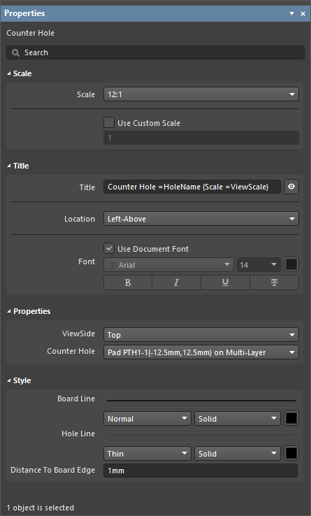 )。
)。
比例 |
|
| Scale, Use Custom Scale |
使用这些选项来配置视图的比例。更多信息请参阅 Working with Views 页面。 |
标题 |
|
| Title, Location, Font |
使用这些选项来配置视图的标题。更多信息请参阅 Working with Views 页面。 |
属性 |
|
| ViewSide | 用于渲染孔图的视图方向。使用下拉菜单从一系列预设视图方向中选择。 |
| Counter Hole | 将被渲染到视图中的、已应用沉孔特征的板设计焊盘孔。使用下拉菜单从所有可用沉孔列表中选择。 |
样式 |
|
| Border Line | 使用下拉列表选择用于绘制视图板线的线宽和线型(当 ViewSide 设置为 Left 时适用)。可用选项在设计空间未选中任何对象时,于 Line Styles 面板的 Properties 区域中定义。更多信息请参阅 Setting Up a Draftsman Document 页面。 使用对应的颜色按钮指定线条颜色。 |
| Hole Line | 使用下拉列表选择用于绘制视图孔几何的线宽和线型。可用选项在设计空间未选中任何对象时,于 Line Styles 面板的 Properties 区域中定义。更多信息请参阅 Setting Up a Draftsman Document 页面。 使用对应的颜色按钮指定线条颜色。 |
| Distance To Board Edge | 当 ViewSide 设置为 Left 时,指定从孔视图到电路板边缘的距离。 |
过孔类型视图
Draftsman 过孔类型视图(Place » Additional Views » Via Type View)根据 IPC-4761 标准表示一种过孔类型, Design Guide for Protection of Printed Board Via Structures。
")
一个已放置的过孔类型视图,示例为 3A 型过孔(在一侧用非导电材料封孔,材料部分进入过孔)
当在设计空间中选中该视图时( ),已放置的过孔类型视图的设置(包括显示的过孔类型与视图的图形样式)可在 Properties 面板中获取。
比例 |
|
| Scale, Use Custom Scale |
使用这些选项来配置视图的比例。更多信息请参阅 Working with Views 页面。 |
标题 |
|
| Title, Location, Font |
使用这些选项来配置视图的标题。更多信息请参阅 Working with Views 页面。 |
属性 |
|
| Via Type | 用于渲染过孔图的、符合 IPC-4761 标准的过孔类型。使用下拉菜单从一系列预设过孔类型中选择。 |
| Side | 使用下拉菜单选择从哪一侧应用覆盖。对于过孔类型 1A、2A、3A、4A 和 6A,可在 Top 或 Bottom 中选择。对于过孔类型 1B、2B、3B、4B、5、6B 和 7,该选项实际上被禁用,仅 Both 可选,并且这是这些过孔类型的默认值。 |
| Layer Stack | PCB 设计层叠(Layer Stack),在 PCB 编辑器的 Layer Stack Manager 中定义,视图将依据该层叠进行渲染。使用下拉菜单从所有可用层叠列表中选择。 |
样式 |
|
| Line Style | 使用下拉菜单选择用于渲染视图外轮廓线的线宽和线型。可用选项在设计空间未选中任何对象时,Line Styles 面板的 Properties 区域中定义。更多信息请参阅 Setting Up a Draftsman Document 页面。使用对应的颜色按钮指定线条颜色。 |
| Hole Fill Color | 使用对应的颜色按钮指定用于渲染视图孔填充(hole fill)的颜色。 |
| Plug Color | 使用对应的颜色按钮指定用于渲染视图塞孔(plug)的颜色。 |
| Cover Color | 使用对应的颜色按钮指定用于渲染视图覆盖(cover)的颜色。 |

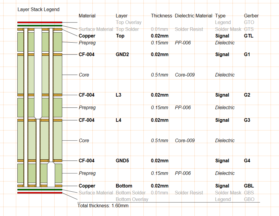
层叠图例
Draftsman 层叠图例视图(Place » Layer Stack Legend)以放大的剖面视图形式呈现电路板的内部结构。它包含层叠中每一层的详细描述与信息,包括与每一层关联的 Gerber 文件。

已放置的层叠图例从源 PCB 的层叠中获取数据,并可按相对层厚与过孔类型显示。
默认情况下,每一层的信息来自电路板层叠中对应的属性,这些属性在 PCB 编辑器的 Layer Stack Manager 中定义。不过,当在设计空间中选中该视图(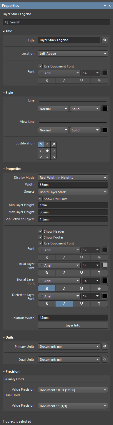 )时,可通过 Properties 面板在 Draftsman 中编辑并扩展层描述属性。
标题 |
|
| Title、 Location、 Font |
使用这些选项配置视图标题。更多信息请参阅 Working with Views 页面。 |
样式 |
|
| 线条 | 使用下拉菜单选择用于渲染视图中“每层表示”与其对应规格表行之间连线的线宽和线型。可用选项在设计空间未选中任何对象时,Line Styles 面板的 Properties 区域中定义。更多信息请参阅 Setting Up a Draftsman Document 页面。使用对应的颜色按钮指定线条颜色。 |
| View Line | 使用下拉菜单选择用于渲染视图中各层表示外轮廓的线宽和线型。可用选项在设计空间未选中任何对象时,Line Styles 面板的 Properties 区域中定义。更多信息请参阅 Setting Up a Draftsman Document 页面。使用对应的颜色按钮指定线条颜色。 |
| Justification | 选择当视图尺寸更新时,用于作为视图位置变化参照的点。 |
属性 |
|
| Display Mode | 在 Min Layer Height 与 Max Layer Height 设置的约束范围内,确定视图图形中每一层表示的渲染高度。使用下拉菜单选择层高度选项:
|
| Width | 设置视图图形的渲染宽度。最小宽度由所包含的过孔类型数量决定。 |
| Source | PCB 设计层叠(在 PCB 编辑器的 Layer Stack Manager 中定义),作为该视图的数据源。 |
| Show Drill Pairs | 启用钻孔层对(过孔类型)的图形表示,这些在 PCB 项目的 Layer Stack Manager 中于 PCB 编辑器里定义(了解更多:Blind, Buried & Micro Via Definition)。 |
| Min Layer Height | 任意层的最小渲染高度。仅当 Display Mode 选项设置为 Real Width in Heights 时,此设置才会影响图形。 |
| Max Layer Height | 任意层的最大渲染高度。仅当 Display Mode 选项设置为 Real Width in Heights 时,此设置才会影响图形。 |
| Gap Between Layers | 设置层图形之间所需的空白间距。 |
| Show Header | 启用/禁用视图表格中的列标题说明。 |
| Show Footer | 启用/禁用视图表格底部的总板厚读数。 |
| Font | 设置视图表格中表头与表尾使用的字体。
|
| Usual Layer Font | 设置用于表格中与电路板外层/表面层相关信息的字体,例如助焊膏层、丝印层和阻焊层。使用提供的选项选择所需的字体类型、大小、颜色和文本属性。 |
| Signal Layer Font | 设置用于表格中与电路板铜信号承载层相关信息的字体,例如顶层/底层以及内层/平面层。使用提供的选项选择所需的字体类型、大小、颜色和文本属性。 |
| Dielectric Font | 设置用于表格中与电路板介质芯层相关信息的字体。使用提供的选项选择所需的字体类型、大小、颜色和文本属性。 |
| Relation Width | 设置层图形与表格之间的距离,并相应决定“层到表格行”指示线的长度。 |
| |
单击按钮打开 Layer Information 对话框 – 见下文。 |
单位 |
|
| Primary Units | 选择将在视图表格中显示的主测量单位类型。使用对应的 |
| Dual Units | 选择将在视图表格中显示的次(双)测量单位类型。使用对应的 |
精度 |
|
| Primary Units | 使用 Value Precision 下拉菜单为主层尺寸表条目设置精度定义(小数点右侧最多五位,最后一位四舍五入)。 |
| Dual Units | 如果启用双单位,使用 Value Precision 下拉菜单为双层尺寸表条目设置精度定义(小数点右侧最多五位,最后一位四舍五入)。 |
 )。有关反钻的更多信息,请参阅
 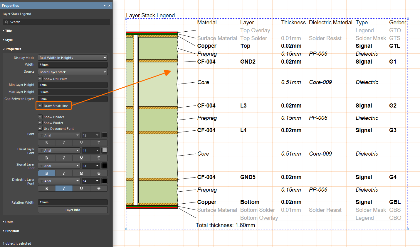 )。
)。
在设计空间中选中层叠图例(layer stack legend)后,点击 Properties 面板中的 ![]() 按钮可打开 Layer Information 对话框,用于编辑层叠图例的表格数据以及图形的颜色/可见性。
按钮可打开 Layer Information 对话框,用于编辑层叠图例的表格数据以及图形的颜色/可见性。
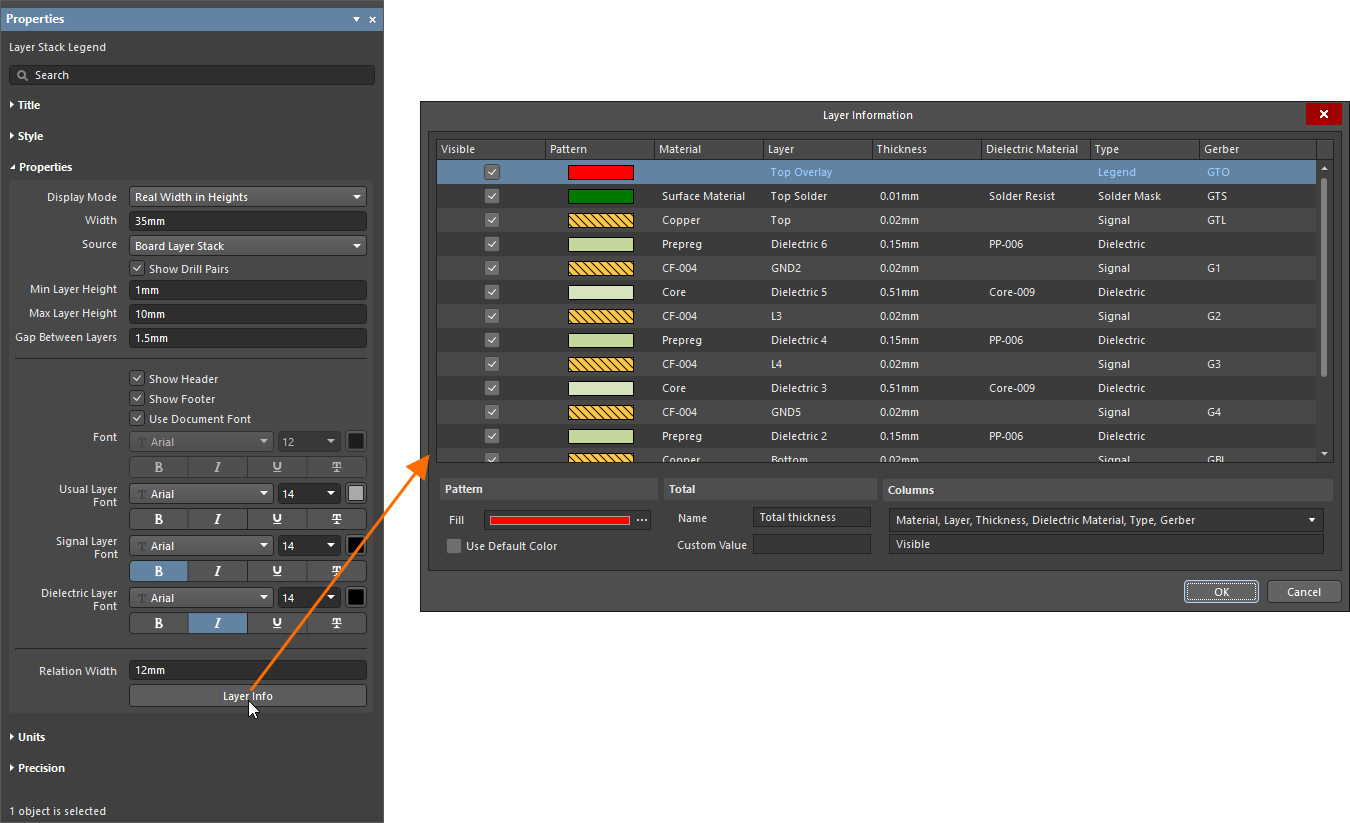
| Grid | 显示设计中每一层的信息,默认包括 Material、Layer、Thickness、 Dielectric Material、Type 和 Gerber。 |
| Pattern |
|
| Total |
|
| Columns | 使用下拉菜单启用或禁用条目旁的复选框,以显示/隐藏表格中对应的列。 |
 )。提供的选项包括:
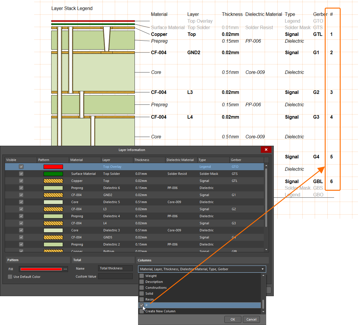 ),将物理层编号(在 PCB 编辑器的
  AI 翻译
AI 翻译