
Arc, Ellipse & Elliptical Arc
Arc
 A placed Arc
An Arc is a non-electrical drawing primitive. It is essentially a curved line segment that can be used when creating graphical symbols, custom sheet borders, and title blocks, etc. A Full Circle is an Arc object that spans 360° (has the same start and end angle).
Arc/Full Circle Object
Arcs are available for placement in the following ways.
From the schematic editor:
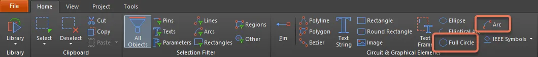
- Choose Home | Graphical Elements | Arc or Home | Graphical Elements | Full Circle from the main menus.

- Right-click in the design space then choose Place » Drawing Tools » Arc or Place » Drawing Tools » Full Circle from the context menu.
From the schematic library editor:
- Choose Home | Circuit & Graphical Elements | Arc or Home | Circuit & Graphical Elements | Full Circle from the main menus.
- Right-click in the design space then choose Place » Arc or Place » Full Circle from the context menu.
After launching the command, the cursor will change to a cross-hair indicating arc/full circle placement mode. Placement is made by performing the following sequence of actions:
- Click or press Enter to anchor the center point of the arc/full circle.
- Move the cursor to adjust the radius of the arc/full circle, then click or press Enter to set it.
- Move the cursor to adjust the start angle for the arc, then click or press Enter to anchor it.
- Move the cursor to adjust the end angle for the arc, then click or press Enter to anchor it and complete placement of the arc.
- Continue placing further arcs/full circles or right-click or press Esc to exit placement mode.
Additional actions that can be performed during placement while the arc/full circle is still floating on the cursor and before the center point of the arc is anchored are:
- Press the Tab key to pause the placement and access the arc mode of the Inspector panel in which its properties can be changed on the fly. Click the design space pause button overlay (
 ) to resume placement.
 - Press the Spacebar to rotate the arc counterclockwise or Shift+Spacebar for clockwise rotation. Rotation is in increments of 90°.
- Press the X or Y keys to mirror the symbol along the X-axis or Y-axis.
- Press the + or - keys (on the numeric keypad) to enlarge or shrink the symbol.
Graphical Editing
This method of editing allows you to select a placed arc/full circle object directly in the design space and change its size, shape, or location graphically.
When an arc/full circle object is selected, the following editing handles are available:
 a selected Arc and Full Circle
- Click and drag A to adjust the radius.
- Click and drag B to adjust the arc/full circle end points (start and end angles).
- Click on the arc/full circle line – away from editing handles – and drag to reposition it. While dragging, the arc/full circle can be:
- Rotated (Spacebar for clockwise and Shift+Spacebar for counterclockwise) about the cursor.
- Mirrored (X or Y keys to mirror along the X-axis or Y-axis) relative to the cursor position.
- Moved in only the X or Y plane (hold Alt), depending on which direction the cursor is first moved from its starting point.
- Duplicated (hold Shift, then drag) to a new arc/full circle object.
Non-Graphical Editing
This method of editing uses the Inspector panel mode to modify the properties of an arc/full circle object.
During placement, the Arc mode of the Inspector panel can be accessed by pressing the Tab key.
After placement, the Arc mode of the Inspector panel can be accessed in one of the following ways:
- Double-clicking on the placed arc/full circle object line.
- Placing the cursor over the arc/full circle object line, right-clicking then choosing Inspector from the context menu.
- If the Inspector panel is already active, by selecting the arc/full circle object.
- With the object selected, click View | Schematic | Inspector from the main ribbons.
Editing Multiple Objects
The Inspector panel supports multiple object editing in which the property settings that are identical in all currently selected objects may be modified. When multiples of the same object type are selected manually, an Inspector panel field entry that is not shown as an asterisk (*) may be edited for all selected objects.
Arc/Full Circle Properties
Schematic and Schematic Library Editor object properties are definable options that specify the visual style, content, and behavior of the placed object.
All arc/full circle object properties are available for editing in the Inspector panel when a placed arc/full circle is selected in the design space.
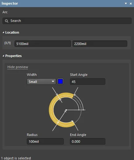
Location
- (X/Y)
- X (first field) - the current X (horizontal) coordinate of the reference point of the arc/full circle, relative to the current design space origin. Edit to change the X position of the arc/full circle. The value can be entered in either metric or imperial; include the units when entering a value whose units are not the current default.
- Y (second field) - The current Y (vertical) coordinate of the reference point of the arc/full circle, relative to the current origin. Edit to change the Y position of the arc/full circle. The value can be entered in either metric or imperial; include the units when entering a value whose units are not the current default.
Properties
- Width - use the drop-down to select the desired width. Click the color box to select the desired color for the arc/full circle.
- Radius - the radius of the arc/full circle.
- Start Angle - the start angle of the arc/full circle.
- End Angle - the end angle of the arc/full circle.
Ellipse
 A placed Ellipse object
Ellipse objects are non-electrical drawing primitive that can be placed on a schematic sheet. They can be filled or unfilled.
Ellipse Object
Ellipse objects are available for placement in the following ways.
From the schematic editor:
- Choose Home | Graphical Elements | Ellipse from the main menus.

- Right-click in the design space then choose Place » Drawing Tools » Ellipse.
From the schematic library editor:
- Choose Home | Circuit & Graphical Elements | Ellipse from the main menus.

- Right-click in the design space then choose Place » Ellipse.
After launching the command, the cursor will change to a cross-hair and you will enter ellipse placement mode. Placement is made by performing the following sequence of actions:
- Click or press Enter to anchor the center of the ellipse.
- Move the cursor to adjust the horizontal radius of the ellipse, then click or press Enter to set it.
- Move the cursor to adjust the vertical radius of the ellipse, then click or press Enter to set it and complete placement.
- Continue placing further ellipses or right-click or press Esc to exit placement mode.
Additional actions that can be performed during placement while the ellipse is still floating on the cursor and before the center point of the ellipse is anchored are:
- Press the Tab key to open the Inspector panel from where properties for the ellipse can be changed on-the-fly.
- Press the Alt key to constrain the direction of movement to the horizontal or vertical axis depending on the initial direction of movement.
- Press the Spacebar to rotate the ellipse counterclockwise or Shift+Spacebar for clockwise rotation. Rotation is in steps of 90°.
Graphical Editing
This method of editing allows you to select a placed ellipse object directly in the design space and change its size, shape, or location graphically.
When an ellipse object is selected, the following editing handles are available:
 A selected Ellipse.
- Click and drag A to change the horizontal radius.
- Click and drag B to change the vertical radius.
- Click anywhere on the ellipse away from editing handles and drag to reposition it. While dragging, the ellipse can be rotated (Spacebar/Shift+Spacebar) or mirrored (X or Y keys to mirror along the X-axis or Y-axis respectively).
Non-Graphical Editing
This method of editing uses the associated Inspector panel mode to modify the properties of an ellipse object.
 During placement, the Ellipse mode of the Inspector panel can be accessed by pressing the Tab key.
After placement, the Ellipse mode of the Inspector panel can be accessed in one of the following ways:
- Double-click on the placed ellipse.
- Placing the cursor over the ellipse then right-click then choose Inspector from the context menu.
- If the Inspector panel is already active, select the ellipse object.
- With the object selected, click View | Schematic | Inspector from the main ribbons.
Editing Multiple Objects
The Inspector panel supports multiple object editing in which the property settings that are identical in all currently selected objects may be modified. When multiples of the same object type are selected manually, an Inspector panel field entry that is not shown as an asterisk (*) may be edited for all selected objects.
Ellipse Properties
Schematic and Schematic Library Editor object properties are definable options that specify the visual style, content, and behavior of the placed object.
All ellipse object properties are available for editing in the Inspector panel when a placed ellipse is selected in the design space.
Properties
- Border - use the drop-down to select the desired border and the color box to select the desired color for the border.
- Fill Color - enable to use a fill color. Click on the colored box to access a drop-down from which you can select the color.
- Transparent - enable to make the object transparent.
Elliptical Arc
 A placed Elliptical Arc object
Elliptical arcs are non-electrical drawing primitive that can be placed on a schematic sheet. They can be filled or unfilled.
Elliptical Arc Object
Elliptical Arcs are available for placement in the following ways:
From the schematic editor:
- Choose Home | Graphical Elements | Elliptical Arc from the main menus.

- Right-click in the design space then choose Place » Drawing Tools » Elliptical Arc.
From the schematic library editor:
- Choose Home | Circuit & Graphical Elements | Elliptical Arc from the main menus.

- Right-click in the design space then choose Place » Elliptical Arc.
After launching the command, the cursor will change to a cross-hair and you will enter elliptical arc placement mode. Placement is made by performing the following sequence of actions:
- Click or press Enter to anchor the center point of the arc.
- Move the cursor to adjust the X radius of the arc, then click or press Enter to set it.
- Move the cursor to adjust the Y radius of the arc, then click or press Enter to set it.
- Move the cursor to adjust the first end point of the arc, then click or press Enter to anchor it.
- Move the cursor to change the position of the arc's other end point, then click or press Enter to anchor it and complete placement of the arc.
- Continue placing further elliptical arcs, or right-click or press Esc to exit placement mode.
Additional actions that can be performed during placement while the arc is still floating on the cursor and before the center point of the arc is anchored are:
- Press the Tab key to pause the placement and access the arc mode of the Inspector panel in which its properties can be changed on-the-fly. Click the design space pause button overlay () to resume placement.
- Press the Spacebar to rotate the arc counterclockwise or Shift+Spacebar for clockwise rotation. Rotation is in increments of 90°.
- Press the X or Y keys to mirror the symbol along the X-axis or Y-axis.
Graphical Editing
This method of editing allows you to select a placed elliptical arc object directly in the design space and change its size, shape, or location, graphically.
When an elliptical arc object is selected, the following editing handles are available:

- Click and drag A to change the vertical radius.
- Click and drag B to change the horizontal radius.
- Click and drag C to adjust the end points.
- Click anywhere on the elliptical arc away from editing handle and drag to reposition it. While dragging, the elliptical arc can be rotated (Spacebar/Shift+Spacebar) or mirrored (X or Y keys to mirror along the X-axis or Y-axis respectively).
Non-Graphical Editing
This method of editing uses the associated Inspector panel mode to modify the properties of an elliptical arc object.

During placement, the Elliptical Arc mode of the Inspector panel can be accessed by pressing the Tab key.
After placement, the Elliptical Arc mode of the Inspector panel can be accessed in one of the following ways:
- Double-clicking on the placed elliptical arc object line.
- Placing the cursor over the elliptical arc object line, right-clicking then choosing Inspector from the context menu.
- If the Inspector panel is already active, by selecting the elliptical arc object.
- With the object selected, click View | Schematic | Inspector from the main ribbons.
Editing Multiple Objects
The Inspector panel supports multiple object editing in which the property settings that are identical in all currently selected objects may be modified. When multiples of the same object type are selected manually, an Inspector panel field entry that is not shown as an asterisk (*) may be edited for all selected objects.
Elliptical Arc Properties
Schematic or Schematic Library Editor object properties are definable options that specify the visual style, content, and behavior of the placed object.
All elliptical arc object properties are available for editing in the Inspector panel when a placed arc is selected in the design space.
Location
- (X/Y)
- X (first field) - the current X (horizontal) coordinate of the reference point of the arc, relative to the current design space origin. Edit to change the X position of the arc. The value can be entered in either metric or imperial; include the units when entering a value whose units are not the current default.
- Y (second field) - The current Y (vertical) coordinate of the reference point of the arc, relative to the current origin. Edit to change the Y position of the arc. The value can be entered in either metric or imperial; include the units when entering a value whose units are not the current default.
Properties
- Width - use the drop-down to select the desired width and the color box to select the desired color for the arc.
- X-Radius - the x-radius of the elliptical arc, which may be edited.
- Y-Radius - the y-radius of the elliptical arc, which may be edited.
- Start Angle - the start angle of the elliptical arc, which may be edited.
- End Angle - the end angle of the elliptical arc, which may be edited.