
Polygon
 A placed Polygon
A polygon is a non-electrical drawing primitive. It is a multi-sided graphical object that can be placed on a schematic sheet. A polygon must have at least three sides and can be filled or unfilled.
Polygon Object
Polygons are available for placement in the following ways.
From the schematic editor:
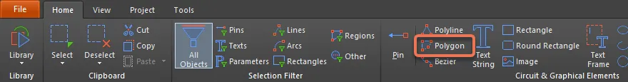
- Choose Home | Graphical Elements | Polygon from the main menus.

- Right-click in the design space then choose Place » Drawing Tools » Polygon.
From the schematic library editor:
- Choose Home |Circuit & Graphical Elements | Polygon from the main menus.
- Right-click in the design space then choose Place » Polygon.
After launching the command, the cursor will change to a cross-hair and you will enter polygon placement mode. Placement is made by performing the following sequence of actions:
- Click or press Enter to anchor the starting point for the polygon.
- Position the cursor then click or press Enter to anchor a vertex; move the mouse and repeat as often as required to define the shape of the polygon.
- After placing the final vertex point, right-click or press Esc to complete placement of the polygon.
- Continue placing further polygons or right-click or press Esc to exit placement mode.
Graphical Editing
This method of editing allows you to select a placed polygon object directly in the design space and change its size and/or shape graphically.
When a polygon object is selected, an editing handle (vertex) will appear at each corner as shown in the image below.

A selected Polygon
- Click and drag on a vertex to move that vertex.
- Click and drag on an edge to move that edge of the polygon.
- Right-click on a vertex point then choose Edit Polygon Vertex n to access the Vertices region of the Inspector panel with the entry for the
nthvertex selected and ready for editing. In addition to editing/adding polygon vertices, the panel can be used to modify the graphical properties of the polygon object. - Click and hold on a vertex then press Delete to remove that vertex.
With the polygon selected, click on an edge to individually select that edge. This polygon 'sub-selection' is distinguished by the associated editing handles for the edge becoming red in color.

Individual edge sub-selection
The associated vertices for the edge can then be edited directly using the List panel, with any changes appearing immediately on the schematic.
Non-Graphical Editing
This method of editing uses the Inspector panel mode to modify the properties of a polygon object.

During placement, the Region mode of the Inspector panel can be accessed by pressing the Tab key. Once the region is placed, all options appear.
After placement, the Region mode of the Inspector panel can be accessed in one of the following ways:
- If the Inspector panel is already open, select the polygon object.
- With the polygon selected, choose View | Schematic | Inspector from the main ribbons.
Editing Multiple objects
The Inspector panel supports multiple object editing, where the property settings that are identical in all currently selected objects may be modified. When multiples of the same object type are selected manually, an Inspector panel field entry that is not shown as an asterisk (*) can be edited for all selected objects.
Polygon Properties
Schematic object properties are definable options that specify the visual style, content and behavior of the placed object.
All Polygon object properties are available for editing in the Inspector panel when a placed Polygon is selected in the design space.
Properties
- Border - use the drop-down to select the border.
- Fill Color - enable to use a fill color. Click the color box to select the desired color of the fill.
- Transparent - check to make the object transparent.
Vertices
- Grid - lists all of the vertex points currently defined for the region in terms of:
- Index - the assigned index of the vertex (non-editable).
- X - the X (horizontal) coordinate for the vertex. Click to edit.
- Y - the Y (vertical) coordinate for the vertex. Click to edit.
- Add - click to add a new vertex point. The new vertex will be added below the currently focused vertex entry and will initially have the same X,Y coordinates as the focused entry. Click
 to remove the currently selected vertex.