The Bill of Materials, or BOM, is a key ingredient of the data set generated from a board design project. This report-type document provides a listing of all components required to build the product, including the bare board, which is essentially the base 'component' upon which all other parts are assembled. The BOM acts as a guide for what needs to be procured to build the product as designed. It also provides a means to calculate cost based on the required number of assembled boards in a requested spin.
The final BOM is generated through a dedicated and powerful report generation engine, the interface to which is known as the Report Manager. The Report Manager dialog is used to:
-
Configure which design properties are to be included in the BOM.
-
Arrange the content in the order needed in the BOM.
-
Apply custom column-level, spreadsheet-like filters if required.
-
Enable different component source options.
-
Enable supplier options.
-
Configure the export file format.
-
Select an Excel BOM template, if the export format is XLS or PDF.
As well as being used to generate a BOM, the
Report Manager can also be configured to generate other component-type outputs, such as a
component cross reference.
For complete control over the BOM configuration process, including an interactive view of supply chain information as well as custom BOM rows and columns, add an ActiveBOM document (BomDoc) to your project. The BomDoc gives instant visibility into the component supply chain and also supports user-defined rows and columns, which is ideal for including those extra items, such as glue, labels, and so on. Creating and managing the BOM through a BomDoc is the recommended approach to BOM Management in Altium Designer.
BOM Creation Choices
The final Bill of Materials output is generated by the Report Manager. The Report Manager can generate output in a variety of formats, including PDF, CSV, TXT, Excel, HTML, or XML.
The Report Manager can extract the source information for the BOM from the following:
-
The project - information is extracted from the schematics, as well as connected databases and the PCB, if required
-
An ActiveBOM document (BomDoc) - the recommended approach.
If the project does not include an ActiveBOM, the Report Manager generates the BOM from the project. Using this approach, the Report Manager is used to perform all of the BOM layout configuration, such as selecting and arranging the columns, filtering out unneeded rows, including supplier information, and so on. The Report Manager is also used to configure the output settings, such as the format, the required Excel template, and so on. With this approach, the BOM is prepared once the design process is complete. The Report Manager can only be used to configure one BOM output. If this approach is used, an OutputJob must be used if you need to set up different BOM output configurations.
The recommended approach is to include an ActiveBOM document (BomDoc) in the project. The BomDoc is a source document that can be added at any stage during the development of the design - in essence, a live parts list. Parts appear in the BomDoc automatically as the components are added to the schematic, and the designer can immediately begin exploring pricing and supply chain options and assign preferred parts. The designer can also select and arrange the columns, apply filters, add line numbers, add additional custom columns, add additional rows for custom items - in short, perform all of the typical BOM preparation steps during the design process. Multiple output configurations can be prepared in the BomDoc, each saved as a BOM Set, with the required BOM Set being selected in the Report Manager for final BOM generation.
If the project includes a BomDoc, this is automatically used as the source for the Report Manager unless you manually override this in an OutputJob by setting the Data Source to [Project] rather than [ActiveBOM document]. When the Project is used as the data source, the Report Manager interface changes slightly, with the inclusion of the Column Grouping feature in the Columns tab of the dialog. More on this below.


 When the project includes a BomDoc, it is used as the source for the Report Manager.
Creating a BOM
The Report Manager can be opened from:
-
The project source schematic documents or from the active PCB document using the schematic or PCB editor's Reports » Bill of Materials command.
A Bill of Materials can also be added if there are no schematic documents in the project. In such an instance, the Bill of Materials report is sourced from the PCB.
-
A Report-type output job configured in an OutputJob.
-
An ActiveBOM, using the Reports » Bill of Materials command.
In each case, the source document(s) will be compiled, and the Report Manager dialog will open. Use this highly configurable, dedicated, and powerful report generation engine to configure the content for the BOM report as required.
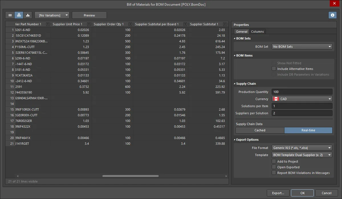
 A Bill of Materials, sourced from the project BomDoc, ready to be generated from the Report Manager.
Options and Controls of the Bill of Materials Report Dialog
View Mode
There are three view modes available to display the list of Items. Select the required mode using the buttons located above the grid:
-
 Flat view - click to display a row for every component.
-
 Base view - click to display a row for each unique component in the project. The Designator column lists the designators of all components of this type.
-
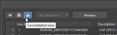
 Consolidated view - click to use when the project includes variants to display a Consolidated BOM for all variants.
The default grouping for the Base and Consolidated views is by the component ItemID for Workspace library components or Library Reference for non-Workspace library components. In the BomDoc, this can be refined by enabling additional or alternative parameters in the
Component Grouping dialog, which is accessed from the BomDoc's
Properties panel. If the
Report Manager is using a BomDoc as the source, it is possible to generate a single BOM for all variants. This is referred to as a Consolidated BOM. To display this, set the
View Mode to
Consolidated View.
Variant
If there are variants defined in the project, they will be listed in the drop-down; choose the required variant. If Consolidated view is enabled, this control is disabled.
To learn more about the different types of variations, refer to
Design Variants.
Preview
Click  to export and open the report in an external application associated with the file type based on the current settings of the File Format and Template options in the Properties panel.
General Tab
The main region of the Report Manager lists all of the components. It is the content that is written into the BOM. If the project does not include a BomDoc, this will be a list of all components placed in the schematic. If the project includes a BomDoc and additional BOM items have been added to it, these will also be included.
BOM Items
-
Show Not Fitted - enable this option to display the Not Fitted Items in the grid.
Components defined as Not Fitted for the chosen variant are removed unless the Show Not Fitted option is enabled. To keep components that are Not Fitted in the BOM and explicitly mark them as such, enable the Show Not Fitted option and enable the Fitted column in the Columns tab of the dialog. For each component, an entry in this column reflects whether each component is Fitted or Not Fitted for the chosen variant. The value entered into the Quantity column for a component that is Not Fitted on the chosen variant is zero (0).
-
Include Alternative Items - enable this option to include alternate items in the BOM. The Alternative Item is displayed on a new line below the original part.
-
Include DB Parameters in Variations - if there are database components that have been placed via a DbLink/DbLib/SVNDbLib file and those components are varied in a design Variant, enable this option to update the database parameters when the selected variant is changed.
The BOM Items list supports the following features:
-
Use the Columns tab in the Properties region of the dialog to display/hide a column.
-
Drag and drop to change the order of columns.
-
Click a column heading to sort by that column; hold Shift to sub-sort on subsequent column(s).
-
Click the Filter icon (
 ) to filter by column values.
-
Select cells using standard Windows selection techniques.
-
Copy cell contents from the BOM Items list.
-
Use the standard Windows shortcuts to scroll through the list of BOM Items:
-
Vertical scroll - MouseWheel Roll
-
Horizontal scroll - Shift + MouseWheel Roll
Supply Chain
Supplier data is available only when generating a report for the project. It is not available when generating a report for a PCB document.
-
Production Quantity - enter the quantity or use the arrows to select the quantity that needs to be ordered to produce the given product quantity.
-
Currency - use the drop-down to select the desired currency.
-
Solutions per Item - use this option to edit the number of manufacturer parts (MPNs) to be displayed for each BOM Item.
-
Suppliers per Solution - use this option to edit the number of suppliers (SPNs) to be displayed for each manufacturer part (MPN).
Supply Chain Data
-
Real-time - click this to display pricing-based data for components with links to Supply Chain Data that are updated in real-time.
-
Cached - click this to display the last cached pricing data if working offline.
Export Options
-
File Format - select a format from the drop-down list. The following file formats are supported:
-
CSV (Comma Delimited) (*.csv)
-
Tab Delimited Text (*.txt)
-
MS-Excel (*.xls, *.xlsx *.xlsm) (uses Microsoft Excel)
-
Generic XLS (*.xls, *.xlsx, *.xlsm) (uses a built-in XLS-format file generator so that this format can be generated without having Microsoft Excel installed)
-
Portable Document Format (*.pdf)
-
Web Page (*.htm, *.html)
-
XML Spreadsheet (*.xml)
-
Template - after selecting a file format, use the drop-down to choose a template format to use for exporting. The options include file-based and Workspace templates.
-
Add to Project - enable to have the generated report added to the project after it is created.
-
Open Exported - enable to open the relevant software application, e.g., Microsoft Excel, once the exported file has been saved.
-
Report BOM Violations in Messages - enable this option to run a check for the ActiveBOM's BOM during BOM generation. Detected violations will be detailed in the Messages panel.
If Altium Designer is connected to a Workspace, the available templates are those included in the Workspace.
If Altium Designer is not connected to a Workspace, the available templates are those in the location specified in the Data Management - Templates page of the Preferences dialog.
Columns Tab
This tab is used to configure which parameters are displayed for each BOM Item and the data sources that are available for those parameters.
-
Search - use this field to quickly locate parameters of interest; the software searches for the typed text anywhere within the Name or Alias strings.
-
Sources - in addition to the data added directly into the BomDoc (
 ), the default data sources available in the ActiveBOM are the schematic component parameters (
 ) and the Workspace library parameters for Workspace Items (
 ). From these sources, the ActiveBOM generates the main project BOM Item grid. The BOM can also include information taken from the following additional data sources:
-
 - enable to include Workspace items.
-
 - enable to include PCB location/rotation/side of board data in the available Columns for each of the components.
-
 - enable to load additional component parameters from an external database (*.DbLib, *.SVNDbLib, or *.DbLink).
-
 - enable to include all detected schematic document parameters across all schematics in the PCB project in the available Columns.
-
 - enable to access a broad range of additional component data for those BOM Items that have been identified by the Altium Parts Provider and show a supply chain solution.
-
Drag a column to group - click, hold and drag a column from the Columns section of the dialog, then drop it in the Drag a column to group section to include it as a grouping parameter. Click the
 icon to remove a parameter from grouping.
-
Columns - list of all available sources of part information available to ActiveBOM. The Columns region can be sorted by clicking on any of the heading fields, including the Visibility (
 ) and Source columns.
-
Visibility - click on the visibility icon in the left column to control the visibility of that column in the main BOM Items grid.
-
Source - displays an icon to show from where that parameter is sourced:
-
 - sourced from the schematic.
-
 - sourced from the BOM.
-
 - sourced from a Workspace.
-
Name - displays the name of the property/parameter as defined in the source document or as entered for a user-created BomDoc column.
-
Alias - if required, an alias can be defined in the source BomDoc to rename a column.
Additional Controls
-
Export - click to generate the report. A standard Windows dialog opens in which you can name the report.
Right-click Menu
-
Preview - click to generate a preview of the report based on the current settings of the File Format and Template options.
-
Copy - use to copy all or selected data.
-
Copy With Header - use to copy and paste the selected data into an external spreadsheet such as Microsoft Excel.
-
Best Fit - merges the contents from the Name and Descriptions columns together so they are closely placed with no excess room between each column.
-
Best Fit All Columns - merges the contents from all columns together so they are closely placed with no excess room between each column.
-
Restore from <.BomDoc> - use to restore from the stated BomDoc.
-
Change PCB Document - use to switch to another PCB document.
-
Change Variant - if there are variants defined for the design, you can generate a Bill of Materials based on a chosen variant. Use this command to change the variant; choose the default variant or no variant.
Although the dialog is referred to as the Report Manager, it is not named as such. It is automatically named according to the type of report being created, which in this case is a Bill of Materials.
The dialog presents the various properties/parameters for all components on the source document(s). Each property/parameter has its own column. The designer simply chooses which data to include in the generated BOM report. Data can be grouped, sorted and filtered as required, with the ability to include additional parametric data from a nominated PCB for the project and/or a linked database, as required.
If the project includes a BomDoc, the default behavior is for the Report Manager to present the component detail in the same way it has been configured in the BomDoc.
The following sections take a closer look at the manipulation of the data to arrive at the desired BOM content prior to exporting the report.
Grouping Components in the BOM
If the project includes an ActiveBOM then the configuration present in the BomDoc is automatically transferred to the Report Manager dialog. This ability to push the BOM setup from ActiveBOM into the Report Manager results in differences in the layout and features available in the Report Manager dialog.
The fundamental difference in the Report Manager dialog is how the like-components are grouped together in a single row:
-
BOM from ActiveBOM - the grouping is defined in ActiveBOM in the Component Grouping dialog. The ActiveBOM editor also includes View Mode controls to instantly switch from a flat view (one row per component) to a grouped view (like components grouped in a single line).
-
BOM from Project - if there is no BomDoc in the project or the Report Manager is opened from an OutputJob that has a Data Source of
[Project], then the Report Manager must be manually configured. In this situation, BOM component grouping is performed in the Report Manager in the Columns tab of the dialog.
Component Grouping - When the BomDoc is the Source
A common approach used in a BOM is to have a row for each unique component. To achieve this, like components must be grouped.
In a BomDoc, the column grouping is configured in the Component Grouping dialog. The designer can then switch column grouping on and off using the View Mode buttons  , instantly switching between Flat View (one part per row) or Base View (parts grouped according to the settings in the ActiveBOM Component Grouping dialog).
If the Report Manager is using a BomDoc as the source, then the dialog includes the same View Mode buttons; use these to switch between one part per row or grouped. The Consolidated View is used where there are variants; this is discussed later in the Catering for Variants section.
These differences in the Report Manager dialog can be seen by comparing the two following images (hover the cursor over the image to change images).
 When the BOM is sourced from a BomDoc there is no Grouped Columns section, as grouping is performed in ActiveBOM.
Typically there is no need to perform any layout changes to the data in the Report Manager dialog if a BomDoc is the source, but it is possible if required using the grouping techniques described below.
Component Grouping - When the Project is the Source
When the project is used as the source for the Report Manager, grouping of like-components is configured in the Report Manager.
Note that if a component has been deleted from a project, its status will be flagged as a violation warning in the BOM Status column in the ActiveBOM.
The Columns tab of the dialog includes the Drag a column to group section, as shown below. Like components will be grouped in the BOM when the contents of all grouped columns match. For example, in the image below, components C1 and C3 have been grouped into the same row of the BOM (the first row), so must have the same values for their Comment, Description and Value parameters.
To group by additional parameters, click, hold and drag on a column name from the Columns list (down the bottom-right of the dialog), then drop it in the Drag a column to group section. Click the delete icon ( ) adjacent to each column name to remove that parameter from being a grouping parameter.
 Enable a column's Show option to have that data included in the BOM.
Configuring the Layout of the BOM Items
Each enabled column will list information for each of the components found in the source document(s) where such information exists. If the component does not have any information for that particular property/parameter, the field will be blank.
Selecting Visible Columns
To choose which columns to show or hide in the grid area of the Report Manager dialog, use the Columns tab of the right-hand Properties pane of the dialog. You can also use the Select columns dialog accessed by right-clicking in a column header in the main grid area, then choosing Select Columns.

The Select columns dialog
Options and Controls of the Select columns Dialog
-
Search - enter characters by which you want the list filtered.
-
Left
 icon - click to toggle between various view modes:
-
(All) - click to display all items featured on the list.
-
(Blanks) - click to display no items featured on the list. This feature will only clear the items in the Select columns dialog, not the Report Manager dialog.
-
(Non blanks) - click to display all items featured on the list, despite any previous alterations to items.
-
(Unchecked) - click to view all unchecked items in the list, which are denoted by the
 icon. Click the icon to uncheck an item.
-
(Checked) - click to view all checked items in the list, which are denoted by the icon. If an item on the list displays the icon, click it to enable the checked icon.
The columns may be filtered to only display checked, blank, non blank, unchecked, check, and all columns. When a view mode is selected, the icon will turn blue  .
.
-
Right icon - click to open a drop-down from where you can choose the column to display. When a specific column is selected, the icon will turn blue .
-
List - this is a list of all possible columns that can display in the Report Manager dialog. When an item displays , that column will be displayed in the Report Manager dialog. When an item displays , that column will not be displayed in the Report Manager dialog. Click the symbols to toggle the show/hide function.
-
Up/Down - click to move the selected item up or down in the list. Only items that are checked may be moved. This determines the order in which the columns will appear in the Report Manager dialog.
Changing Column Order
The order of the columns in the data region of the dialog can be changed by clicking and dragging a column heading to a new location, as required. While moving a column header, valid drop locations are indicated by two vertical white arrows.
Adjusting the Column Widths
If not all data is displayed in a particular column, either drag the applicable column separator to widen the column or use the right-click Best Fit command. This command widens the column according to the longest field entry (or header string length) in that column. To resize all columns to fit their longest field entry (or header string length), use the Best Fit all Columns command.
Sorting Data within Columns
Data in any given column can be sorted in ascending or descending order by clicking on the column header (away from the filter icon). Note that all columns will be affected but the rows will be sorted according to the column that was clicked. Multi-column sorting is also supported; hold the Shift key as you click on subsequent column headers to sub-sort by that second column.
Custom Filtering
In some cases, you may need to exclude specific parts from the BOM report, such as fiducials, or perhaps a unique set of components need to be listed with a particular designator root and/or footprint. To support this, the dialog provides the ability to apply custom filtering, giving you full control over the content of the BOM.
To apply filtering, click the filter icon (  ), located to the right of each column header. Notice that the subsequent menu lists all individual row entries for quick selective filtering, or select the (Custom…) entry to access the Filter Editor dialog. Use the dialog to build up the filter, which can be based on values in any column. Refer to the Filter Editor dialog page for more information.
Once a filter has been applied, the filter icon turns blue (  ) to indicate custom filtering is in force for that column. The filter currently applied is reflected at the bottom-left of the data region and can be re-edited by clicking the pencil icon, as shown below.
 An example of using custom filtering.
To clear the current filter being applied to the data set, click on the small cross (Clear Filter) to the right of the filter expression at the bottom of the data region.
Where the Layout is Stored
The layout defined in the Report Manager is stored so that it can be re-applied the next time the dialog is opened. The location of where the layout is stored changes depending on where the Report Manager is sourcing the BOM information from and where the Report Manager is opened from.
-
If the source for the Report Manager is an ActiveBOM BomDoc: the current layout defined in the BomDoc is transferred to the Report Manager each time it is opened. Layout changes made in the Report Manager are not retained; use the BOM Sets feature in ActiveBOM to configure specific report layouts.
-
If the source for the Report Manager is the project (or the PCB):
-
And the Report Manager is opened from the schematic or PCB editor's Reports menu; the Report Manager layout is stored in the project file.
-
And the Report Manager is opened from an OutputJob; the Report Manager layout is stored in the OutJob file. This is done so that the OutJob can be transferred from one project to another project.
Including Additional Information Directly to the BOM
Source information for a Bill of Materials has, in the past, been taken from the property information of the placed components for the design. That can lead to a lot of information attached to a schematic that is only used for the BOM.
Beyond the information derived from the schematic components, the Report Manager can also extract information from connected data sources, including:
 a Workspace (for Workspace library components)
 the Altium Cloud Services (for components placed from the Manufacturer Part Search panel)
 a database, for components linked to that database
 the PCB
 the schematic document parameters
Enable the required Sources in the Columns tab of the Report Manager, then enable the required parameter(s) in the Columns list.
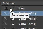
To cluster parameters in the Columns list by their source, click the unlabeled Data Source header section, as shown below.
Including Database Information
Source information for a Bill of Materials (BOM) has, in the past, been taken from the parameter information of the placed components for the design. But that can lead to a lot of information attached to a schematic that is only ever used for the BOM. If components are linked to an external database using a database library file, the Report Manager is able to extract any other record information that has not been added to the components as design parameters directly from that database. Click the button in the Sources region of the Columns tab to enable databases as a source. This option will only be available if one or more components in the design are linked to an external database.
Database parameters can be included from an external database, regardless of the method employed to link to that database: *.DbLib, *.SVNDbLib, or *.DbLink. Look for the  icon in the Columns list to distinguish a parameter that exists for one or more placed components in the linked external database to include in the BOM. Click the visibility icon so it becomes an eye (
 ), to include that column (parameter) in your BOM.

Include additional component information that exists only in an external database.
For a design that includes
Variants, the parameters used to query the database are varied in the
Variant Management dialog. Since those parameter values only exist in the
Variant Management dialog, they are only used to query and match records in the database when a BOM is being configured for generation. To do this, ensure the sub-option -
Include DB Parameters in Variations - is enabled in the
General tab of the
Report Manager properties.
Including PCB Information
Source information for a Bill of Materials can include property information taken from the PCB, in the event the designer needs to customize and use the report generation for special-purpose BOM. An example would be for generation of a pick and place file, where the placement machine operator wants PCB data (such as X, Y location), along with other component specific parameters, configured in a specific column order and file format.
Click the button in the Sources region of the Columns tab to enable the PCB as a source. This option will only be available if there is a PCB document in the project file. If the project includes multiple PCB documents, the Choose PCB to Use dialog will appear.
 Choose which PCB to use as a source for the BOM.
To switch to another PCB document, click the button in the Sources region to disable that PCB as a source, then click it again to re-open the Choose PCB to Use dialog and select a different PCB.
Including Supplier Data in the BOM
Being able to cost a project and determine the quantities of design components to be ordered from suppliers/distributors is an essential part of the overall design process. If the design components have been placed from a Workspace (and have Part Choices defined), or from the Manufacturer Part Search panel, those components will include links to the supply chain. If they have links to the supply chain then linked supplier data – including pricing and stock information – can be included at design release time in the Bill of Materials, by enabling the appropriate parameter Columns.
Supplier data is only available when generating a Bill of Materials for the project. It is not available when generating a Bill of Materials for a PCB document and is also not included when generating a Simple BOM.
The following supplier-based data can be included in a Bill of Materials by enabling the checkbox of each desired item in the Columns region:
-
Manufacturer n - name of the manufacturer.
-
Manufacturer Lifecycle n - manufacturer lifecycle status, if available.
-
Manufacturer Part Number n - manufacturer part number.
-
Supplier n - name of the Supplier.
-
Supplier Currency n – alphabetic code for the chosen currency used for pricing data.
-
Supplier Order Qty n – the higher value of either: (Item Quantity * Production Qty), or; Minimum Order Qty (MOQ)
-
Supplier Part Number n – part number for the Supplier Item.
-
Supplier Stock n – how many units of the item the Supplier has in stock.
-
Supplier Subtotal per Board n – Supplier Unit Price multiplied by the Item Quantity, resulting in the subtotal for that item. Note that this value does not consider MOQ.
-
Supplier Subtotal n – Supplier Unit Price multiplied by the Supplier Order Quantity, resulting in the subtotal for that item with MOQ taken into consideration.
-
Supplier Unit Price n – cost per unit of the Supplier Item (without regard to any MOQ).
The BOM uses indexed sets of supplier-related data to cater for components that have more than one linked Supplier Item, for example Supplier 1, Supplier Currency 1, etc., Supplier 2, Supplier Currency 2, etc., and so on.
Pricing and stock information is sourced directly from enabled Part Providers. Having these parameters added to the components has no bearing on the population of data in the BOM.
To learn more, refer to the page, Linking to Part Supply Chain Data.
Specifying the Production Quantity
You can fully cost a project based on the number of units of the product that it is intended to produce, i.e. the Production Quantity. Use the Production Quantity field in the Supply Chain region of the Report Manager to specify the required value. It is important to define this field as this is used during supply chain searching to check component availability and also the price per unit for the available supplier price breaks.
The value entered into the Production Quantity field is used to determine the Supplier Order Qty – the quantity of the component that would need to be ordered to produce the given product quantity. This is calculated by multiplying the Quantity (of each particular component) by the specified Production Quantity. Note that for components that have a Minimum Order Quantity (MOQ), the Supplier Order Qty is the higher value of either: (Item Quantity * Production Qty), or; Minimum Order Qty (MOQ).
In turn, the Supplier Order Qty is used to determine the Supplier Unit Price that applies. Remember that suppliers typically offer various quantity pricing levels (price breaks), depending on how many units of an item are purchased.
Changing Supplier Currency
The currency used for pricing-related data in a Bill of Materials can be specified from the range of supported currencies. Choose the required currency in the Supply Chain region of the Report Manager. The chosen currency will affect the following data columns, which can also be included in the BOM:
-
Supplier Unit Price n
-
Supplier Currency n
-
Supplier Subtotal per Board n
-
Supplier Subtotal n
 Choose from a list of supported currencies when outputting pricing data in a Bill of Materials.
Using Cached Pricing Data in BOM Parameters when Offline
When working online (connected to the internet and signed in to an Altium Live account) pricing-based data for components with Live Links to Supplier Data will be updated. When generating a BOM, the latest pricing at that point in time will be used. For specific currencies, the exchange rates are updated on a daily basis.
When working offline, you can use the last cached pricing data in the pricing-based parameters in the BOM. To do this from the Report Manager, click the Cached button in the Supply Chain Data region of the dialog.
Catering for Variants
If there are variants defined for the design, you can generate a Bill of Materials based on a chosen variant.
To do this, select the required variant from the variant drop-down available at the top of the Report Manager dialog. The Report Manager banner will indicate the currently selected variant.
 Base the BOM report on a specific variant, the dialog banner shows which variant is currently being used.
Revert back to using the base design by choosing the [No Variations] entry in the drop-down.
The data region of the dialog will update accordingly:
-
Components defined as Not Fitted for the chosen variant are removed, unless the Show Not Fitted option is enabled.
-
Parameter values are updated with those from the chosen variant where they vary from the base design.
To keep components that are Not Fitted in the BOM and explicitly mark them as such, enable the Show Not Fitted option and also enable the Fitted column in the Columns tab of the dialog. For each component, an entry in this column reflects whether each component is Fitted or Not Fitted for the chosen variant. The value entered into the Quantity column for a component that is Not Fitted on the chosen variant, is zero (0).
Variant Support when the Source is a BomDoc
If the Report Manager is using a BomDoc as the source, it is possible to generate a single BOM for all variants. This is referred to as a Consolidated BOM, to display this, set the View Mode to Consolidated View.
Two additional variant-specific additional columns are automatically displayed, for each variant:
-
Qty@<VariantName>
-
Price@<VariantName>
These variant-specific columns are automatically assigned Alias names, in the format <VariantName> - Qty and <VariantName> - Price.
Exporting the BOM
Once the content for the BOM is defined and organized as required, the report can be generated – either printed, or exported, into one of several file formats.
Controls for exporting the BOM data are located in the Export Options region of the Report Manager.
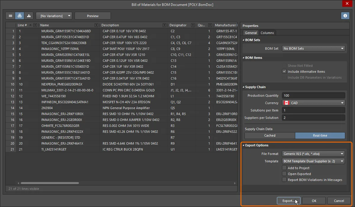
To export the Bill of Materials, perform the following steps:
-
Use the File Format drop-down menu to choose the format in which to export the BOM data. The following formats are supported:
-
CSV (Comma Delimited) (*.csv)
-
Tab Delimited Text (*.txt)
-
MS-Excel (*.xls, *.xlsx) (uses Microsoft Excel)
-
Generic XLS (*.xls, *.xlsx) (uses a built-in XLS-format file generator, so that this format can be generated without having Microsoft Excel installed)
-
Portable Document Format (*.pdf)
-
Web Page (*.htm, *.html)
-
XML Spreadsheet (*.xml)
-
If the export format is Excel, an Excel template can be applied to the exported data.
A Workspace BOM Template can also be used as a configuration data item in one or more defined Environment Configurations. An environment configuration is used to constrain a designer's working environment to only use company-ratified design elements. Environment configurations are defined and stored within the Team Configuration Center – a service provided through the Workspace. Once you have connected to the Workspace, and chosen (if applicable) from the selection of environment configurations available to you, Altium Designer will be configured, with respect to use of BOM Templates. If the chosen environment configuration has one or more defined BOM templates, then only those defined templates can be used. If the chosen environment configuration applicable to you does not have any BOM templates specified/added, or is set to Do Not Control, then these will remain manually definable. In other words, you are free to use local, file-based templates. For more information, see Environment Configuration Management (Altium 365 Workspace, Enterprise Server Workspace).
-
To open the exported file in the associated software application, enable the Open Exported option.
-
To add the generated report to the project after it is created, enable the Add to Project option.
-
Enable the Report BOM Violations in Messages option to run a check for the ActiveBOM during BOM generation. Detected violations will be detailed in the Messages panel.
-
Click the Export button then use the dialog that appears to specify where and under what name the BOM report is to be saved. Click Save to create the export.
Several example templates are provided with Altium Designer in the \Templates folder of the installation user-files.
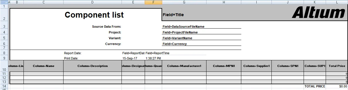
Mapping Design Data into the BOM
A common approach to BOM generation is to export the BOM data from Altium Designer into a company-preferred Excel format spreadsheet. Altium Designer data is mapped into the spreadsheet by including special Field and Column statements in the Excel template. This can be used to specify the desired layout. The Field statement is used to map a single parameter, for example, a document parameter called Title. The Column statement is used to map per-component parameters, for example, the Designator component parameter.
Fields
The Field statement is used to map a document or project parameter (both local and Workspace-side project parameters are supported), for example, Title, into the BOM. The Field declaration is replaced by the passed value, as shown in the images below.
Fields are used in the format:
Field=<FieldName>
An example is Field=Currency
Fields should be defined above or below the Column region of the template.
Columns
Column declarations are used to map per-component parameters, for example, each component's Designator, Description, user-defined parameters, and so on. This can also include: line numbers, PCB location data, and custom column data entered into the BomDoc if there is a BomDoc in the project. The Column declaration in the template is replaced by the ColumnName string, with each row below being populated by that column value for each BOM Item, as shown in the two images below.
Columns are used in the format:
Column=<ColumnName>
An example is Column=Designator
Notes:
-
Each column defined in the template must be displayed in the Report Manager for that column of data to be transferred. For example, in the images below, the
Line # column is displayed in the Report Manager, so can be included in the BOM (using the syntax Column=Line #). Note that the Line # column is only available as a user-configurable column when generating reports from an ActiveBOM BomDoc.
-
The data will be presented in the Excel spreadsheet in the same row order as the Report Manager. Use the Report Manager's column sorting and sub-sorting feature to sort the rows as required.

-
Example templates are included in the \Templates folder of the installation user files.
-
Available templates are configured in the Data Management - Templates page of the Preferences dialog.
-
The default location for unmanaged (Local) templates is configured in the Local Templates folder field on that page in the Preferences dialog.
-
For a managed design, the available (Server) templates are stored in the \Templates\BOM Templates folder of your Altium Workspace (managed content server). These are only listed in the Preferences dialog when you are connected to a Workspace.
-
The list of templates available in the Report Manager Template dropdown is based on the current configuration of templates in the Preferences dialog. Ensure that the Templates visibility option is configured to suit your needs.
-
Excel templates support hiding rows or columns. This feature has been used in some of the example templates to hide the Column = <ColumnName> declarations. To display hidden rows or columns in Excel, select all cells in the template, then right-click anywhere on the sheet and choose the Unhide command (show image).
Mapping Project-Level, BOM Header Information
Project-level information is typically mapped using the Field= statement in the header of the BOM document.
Available System Fields
| Field |
Description |
| Currency |
The currency that has been chosen in the Supplier Options region of the Report Manager dialog. |
| DataSourceFileName |
The filename of the source used for the BOM data. |
| DataSourceFullPath |
The full path + filename of the source used for the BOM data. |
| GeneratorDescription |
For a BOM, this field displays Bill of Materials. |
| GeneratorName |
Name of the generator - BOM when output is generated by the Report Manager. |
| OutputName |
Title of the BOM, as displayed in the Report Manager (excluding the text "For BOM Document [<DataSourceFileName>]"). |
| OutputType |
For a BOM, this field displays BOM_PartType. |
| PCBDataSourceFileName |
The filename of the PCB data source. |
| ProductionQuantity |
Production quantity defined in the Report Manager dialog. |
| ProjectFileName |
Name of the PrjPcb file (including file extension). |
| ProjectFullPath |
Full path + the project filename. |
| ReportDate |
Date on which the report was created. |
| ReportDateTime |
Date and time at which the report was created. |
| ReportTime |
Time at which the report was created. |
| TotalQuantity |
Sum of the values in the BOM Items Quantity column. |
| Title |
Title displayed at the top of the BOM Reports dialog. |
| VariantName |
Name of the variant, as defined in the Variant Management dialog. |
| VersionControl_RevNumber |
Current revision of the BomDoc. |
| VersionControl_ProjFolderRevNumber |
Current revision of the project (incremented when a Commit Whole Project is performed). |
| <UserProjectParameter_n> |
Displays the value assigned to the user-defined UserProjectParameter-n. |
Mapping Document and Project Parameters
As well as the Field statements listed above, schematic Document Parameters (both default and user-defined parameters entered in the schematic document's Properties panel) and Project Parameters (Options for PCB Project dialog) can also be used as Fields, or as Columns.
Default Document Parameters
| Address1 |
Address2 |
Address3 |
| Address4 |
ApprovedBy |
Author |
| CheckedBy |
CompanyName |
ConfigurationParameters |
| CurrentDate |
CurrentTime |
Date |
| DocumentFullPathAndName |
DocumentName |
DocumentNumber |
| DrawnBy |
Engineer |
ImagePath |
| Index |
ModifiedDate |
Organization |
| Revision |
Rule |
SheetNumber |
| SheetTotal |
Time |
|
If the same parameter exists as both a document parameter and a project parameter, the project parameter takes precedence. If the same document parameter exists in multiple documents, the document parameter that is higher up in the hierarchy takes precedence.
Mapping BOM Item Information
The core region of a BOM is the grid of BOM Items, typically using a row for each component. Each column in this grid represents a component property, such as the designator, value, and so on. Columns are defined by entering the component property/parameter (BOM column heading), in the format:
Column=ColumnName
An example would be Column=Description, or Column=Designator
Column information can be taken from several sources, including:
Component Parameters
These ColumnNames are available for all components
| Comment |
ComponentKind |
Description |
| Designator |
DesignItemId |
Footprint |
| LibRef |
LogicalDesignator |
PartType |
| PhysicalPath |
Quantity |
UniqueIdName |
| UniqueIdPath |
<UserParameter_n> |
|
PCB Component Data
PCB component location information can also be included. In order to use these columns, the Include Parameters From PCB option must be enabled in the Report Manager dialog.
| Center-X(Mil) |
Center-Y(Mil) |
Center-X(mm) |
Center-Y(mm) |
| Pad-X(Mil) |
Pad-Y(Mil) |
Pad-X(mm) |
Pad-Y(mm) |
| Ref-X(Mil) |
Ref-Y(Mil) |
Ref-X(mm) |
Ref-Y(mm) |
| Layer |
Rotation |
|
|
Supplier Data
It is possible to retrieve online data from suppliers and include it in the BOM. Note that these are updated live, and are retrieved when the BOM is generated. Multiple suppliers can be set up for each component. In the table below, these have been described as Supplier Info x - replace x with the appropriate number.
| Manufacturer x |
Manufacturer Part Number x |
Supplier x |
| Supplier Currency x |
Supplier Order Qty x |
Supplier Part Number x |
| Supplier Stock x |
Supplier Subtotal x |
Supplier Unit Price x |
User-Defined Columns
User-defined columns are includes in the same way:
Column=ColumnName
Making an Excel-based BOM Template Available for Use
An Excel-based BOM template (prepared as described in the Mapping Design Data into the BOM section above) can be made available for use when preparing a BOM for export by uploading the relevant Excel template file (*.xls, *.xlsx, *.xlt, *.xltx) into your Workspace. To do this, open the Templates tab of the Data Management – Templates page of the Preferences dialog and select the BOM or Load from File command from the menu of the Add button or the Add context menu of the template grid. In the Open dialog (a standard Windows open-type dialog) that opens, select the Microsoft Excel File (*.xlt;*.xltx;*.xltm;*.xls;*.xlsx;*.xlsm) option in the drop-down at the right of the File name field and use the dialog to browse to, and open, the required file that will be uploaded into the initial revision of the new Workspace BOM Template created automatically in a Workspace folder of the BOM Templates type.

If the required Excel template file resides in the Local Template folder (defined at the bottom of the Data Management – Templates page of the Preferences dialog) and is listed under the Local entry of the template grid, it can be migrated to a new Workspace BOM Template by right-clicking on it and selecting the Migrate to Server command. Click the OK button in the Template migration dialog to proceed with the migration process – as stated in this dialog, the original Excel template file will be added to a Zip archive in the local template folder (and hence it will not be visible under the Local template list).
If you need to change the Excel template stored in a Workspace BOM Template, upload the required new Excel file to that Workspace template. From the Templates tab of the Data Management – Templates page of the Preferences dialog, right-click on the template entry and choose the Upload command from the context menu. In the Open dialog, browse to and select the required file. The new template will be stored in the next revision of that Workspace template.
-
To open the Excel BOM template file stored in a revision of a Workspace BOM template, browse to this revision in the Explorer panel and select that file on the Details aspect view tab for the revision, then right-click and choose the Open command from the context menu. The file will be opened in Excel, where installed.
-
To download the Excel BOM template file stored in a revision of a Workspace BOM template, browse to this revision in the Explorer panel and select that file on the Details aspect view tab for the revision, then right-click and choose the Download command from the context menu. Nominate the target folder to receive the file, in the subsequent Choose destination folder dialog.
Generating the BOM from an Output Job
A Bill of Materials can also be configured and generated as part of an Output Job Configuration file (*.OutJob). Add an Output Job to the project via the New menu, or right-click on the project in the Projects panel.
To add a BOM output generator to an open Output Job file, click Add New Report Output under the Report Outputs category and choose Bill of Materials from the pop-up menu. A second menu is provided from which you can specify the data source (which source document(s) is to be used when the BOM report is generated). Only applicable data sources are available, leaving less room for error.

The data source for a BOM can be a single, specific source schematic document, the PCB design document, all source schematic documents (the [Project] entry), or an ActiveBOM document.
Once added, double-click the new entry to access the Report Manager and customize the BOM as outlined in this document. Once the output generator is configured, link it to the relevant Output Containers. A BOM report can be generated as file-based output or published as a PDF. It can also be printed by sending directly to a printing device as Hard Copy (through a configured Print Job).
 Enable the output for the selected Output Container then click Change to configure the output, ready to generate a BOM report from an Output Job file.
Settings defined in the Report Manager when generating a BOM from the Schematic or PCB are stored in the project file and are distinct from those defined for the same output-types in an Output Job file. While generation from the source editor can be good for quick testing, the Output Job file provides a portable solution that can be used across projects without having to set up a favorite BOM customization again and again.
Publishing to PDF Based on an Excel Template
From an Output Job file, the BOM report can also be published to PDF format based on a nominated Excel template by performing the following:
-
When configuring the BOM output generator:
-
Set the File Format in the Export Options region to Microsoft Excel Worksheet (*.xls, *.xlsx, *.xlt, *.xltx).
-
Specify the required Excel template using the Template field in the Excel Options region.
-
Link the BOM output generator to the required (and configured) PDF Output Container, as shown in the image above. The following rules are applied to determine the size of the spreadsheet to print to PDF:
-
Cells to the right of the right-most column header are not included in the output.
-
Cells below the lowest text cell are not included unless they contain horizontal borders and/or background colors and are not separated from the main section of the BOM by more than ten blank rows.
Preparing a Component Cross Reference Report
The Component Cross Reference Report is a list of components, based on the schematic sheet that they are on in the design. Select Reports » Component Cross Reference from a schematic document or double-click on a Component Cross Reference Report that has been added to an OutJob to access the Component Cross Reference Report dialog where the report can be configured.

Options and Controls of the Component Cross Reference Report Dialog
View Mode
There are three view modes available to display the list of Items. Select the required mode using the buttons located above the grid:
-
Flat view - click to displays a row for every component.
-
Base view - click to display a row for each unique component in the project. The Designator column lists the designators of all components of this type.
-
Consolidated view - click to use when the project includes variants to display a Consolidated BOM for all variants.
The default grouping for the Base and Consolidated views is by the component ItemID for Workspace library components or Library Reference for non-Workspace library components. In the BomDoc, this can be refined by enabling additional or alternative parameters in the
Component Grouping dialog, which is accessed from the BomDoc's
Properties panel. If the
Report Manager is using a BomDoc as the source, it is possible to generate a single BOM for all variants. This is referred to as a Consolidated BOM, to display this, set the
View Mode to
Consolidated View.
Variant
If there are variants defined in the project, they will be listed in the drop-down; choose the required variant. If Consolidated view is enabled, this control is disabled.
To learn more about the different types of variations, refer to
Design Variants.
Preview
Click to export and open the report in an external application associated with the file type based on the current settings of the File Format and Template options in the Properties panel.
General Tab
The main region of the Report Manager lists all of the components. If the project does not include a BomDoc, this will be a list of all components placed in the schematic. If the project includes a BomDoc and additional BOM items have been added to it, these will also be included.
Bom Items
-
Show Not Fitted - enable this option to display the Not Fitted Items in the grid.
Components defined as Not Fitted for the chosen variant are removed unless the Show Not Fitted option is enabled. To keep components that are Not Fitted in the BOM and explicitly mark them as such, enable the Show Not Fitted option and enable the Fitted column in the Columns tab of the dialog. For each component, an entry in this column reflects whether each component is Fitted or Not Fitted for the chosen variant. The value entered into the Quantity column for a component that is Not Fitted on the chosen variant is zero (0).
-
Include Alternative Items - enable this option to include alternate items in the BOM. The Alternative Item is displayed on a new line below the original part.
-
Include DB Parameters in Variations - if there are database components that have been placed via a DbLink/DbLib/SVNDbLib file and those components are varied in a design Variant, enable this option to update the database parameters when the selected variant is changed.
Supply Chain Data
-
Production Quantity - enter the quantity or use the arrows to select the quantity that needs to be ordered to produce the given product quantity.
-
Currency - use the drop-down to select the desired currency.
-
Real-time - click this to display pricing-based data for components with links to Supply Chain Data that are updated in real-time.
-
Cached - click this to display the last cached pricing data if working offline.
Export Options
-
File Format - select a format from the drop-down list. The following file formats are supported:
-
CSV (Comma Delimited) (*.csv)
-
Tab Delimited Text (*.txt)
-
MS-Excel (*.xls, *.xlsx *.xlsm) (uses Microsoft Excel)
-
Generic XLS (*.xls, *.xlsx, *.xlsm) (uses a built-in XLS-format file generator, so that this format can be generated without having Microsoft Excel installed)
-
Portable Document Format (*.pdf)
-
Web Page (*.htm, *.html)
-
XML Spreadsheet (*.xml)
-
Template - after selecting a file format, use the drop-down to choose a template format to use for exporting. The options include file-based and Workspace templates.
-
Add to Project - enable to have the generated report added to the project after it is created.
-
Open Exported - enable to open the relevant software application, e.g., Microsoft Excel, once the exported file has been saved.
Columns Tab
This tab is used to configure which parameters are displayed for each BOM Item and the data sources that are available for those parameters.
-
Search - use this field to quickly locate parameters of interest, searches for the typed text anywhere within the Name or Alias strings.
-
Sources - in addition to the data added directly into the BomDoc (), the default data sources available in the ActiveBOM are the schematic component parameters () and the Workspace library component parameters for Workspace Items (). From these sources, the ActiveBOM generates the main project BOM Item grid. The BOM can also include information taken from the following additional data sources:
-
- enable to include Workspace items.
-
- enable to include PCB location/rotation/side of board data in the available Columns for each of the components.
-
- enable to load additional component parameters from an external database (*.DbLib, *.SVNDbLib, or *.DbLink).
-
- enable to include all detected schematic document parameters across all schematics in the PCB project in the available Columns.
-
- enable to access a broad range of additional component data for those BOM Items that have been identified by the Altium Parts Provider and show a supply chain solution.
-
Drag a column to group - click, hold and drag a column from the Columns section of the dialog, then drop it in the Drag a column to group section to include it as a grouping parameter. Click the icon to remove a parameter from grouping.
-
Columns - list of all available sources of part information available to ActiveBOM. The Columns region can be sorted by clicking on any of the heading fields, including the Visibility () and Source columns.
-
Visibility - click on the visibility icon in the left column to control the visibility of that column in the main BOM Items grid.
-
Source - displays an icon to show from where that parameter is sourced:
-
- sourced from the schematic.
-
- sourced from the BOM.
-
- sourced from a Workspace.
-
Name - displays the name of the property/parameter as defined in the source document, or as entered for a user-created BomDoc column.
-
Alias - if required, an alias can be defined in the source BomDoc to rename a column.
Additional Controls
-
Export - click to generate the report. A standard Windows dialog opens in which you can name the report.
Right-click Menu
-
Preview - click to generate a preview of the report based on the current settings of the File Format and Template options.
-
Copy - use to copy all or selected data.
-
Copy With Header - use to copy and paste the selected data into an external spreadsheet such as Microsoft Excel.
-
Best Fit - merges the contents from the Name and Descriptions columns together so they are closely placed with no excess room between each column.
-
Best Fit All Columns - merges the contents from all columns together so they are closely placed with no excess room between each column.
-
Restore from <.BomDoc> - use to restore from the stated BomDoc.
-
Change PCB Document - use to switch to another PCB document.
-
Change Variant - if there are variants defined for the design, you can generate a Bill of Materials based on a chosen variant. Use this command to change the variant, choose the default variant, or no variant.

