
Placement Rule Types
At a Glance
- Understand how Room Definition rules can contain or exclude components, define named board regions, and support the scope of other design rules.
- Learn the key constraints and behaviors of placement rules, including room locking, component locking, confinement mode, and component clearance settings.
- See how Altium Designer evaluates placement through Online DRC and Batch DRC, helping you manage spacing and placement accuracy more effectively.
The design rules of the Placement category are described below.

The Placement category of design rules.
Room Definition
This rule can be used in the following ways:
-
To specify a rectangular or polygonal region on the top side or the bottom side of the board, where components are either allowed in, or not allowed in.
-
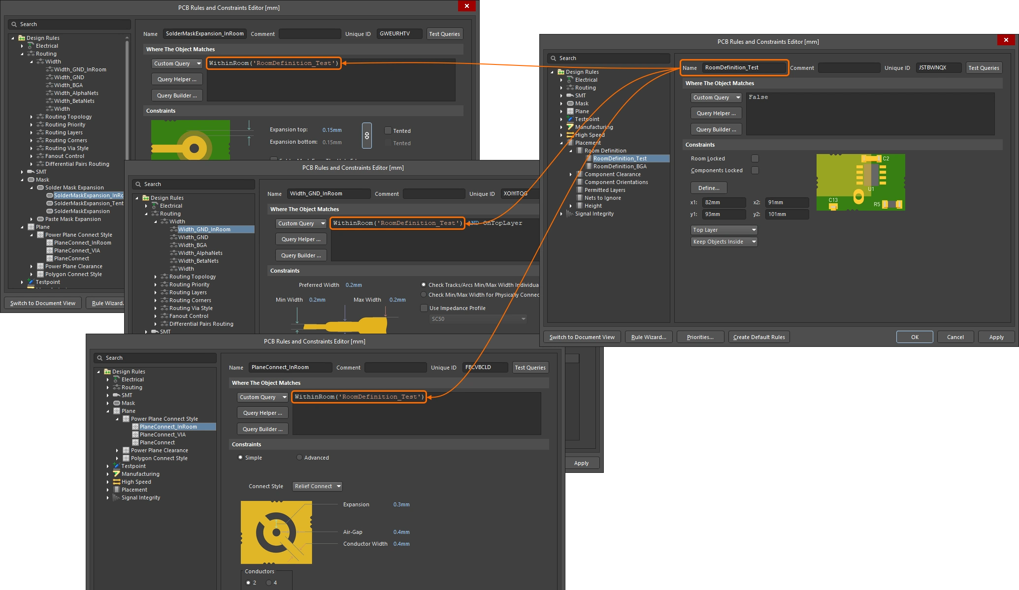
To define a named region (area) on the board, where the named region is then used to scope other design rules. When used in this way the room simply defines an area of the board. There is an example of this approach in the description below.
Constraints
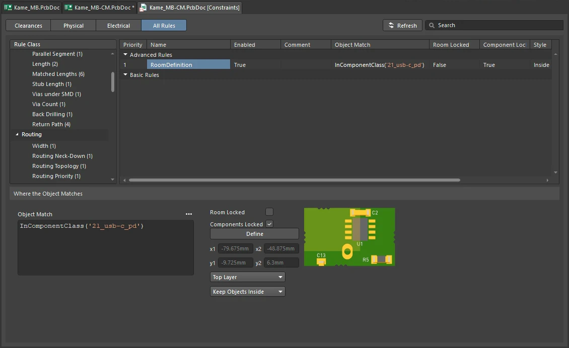
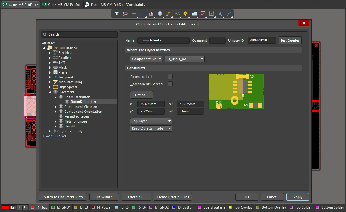
Room Definition Constraints
| Default Rule | Not required. |
| Room Locked | Allows you to lock the room in its current position within the design, preventing accidental movement. If you attempt to move the room when it has been locked, a warning dialog will appear asking whether you wish to go ahead with the move. The locked status of the room remains in force after such a manual-override movement. |
| Components Locked | Allows you to lock the position of components arranged within, and associated to, the room. If you attempt to move a component within a room when this option is enabled, as you move the component the entire room and all components within it, will also move. |
| Define button | Enables you to define the area and location of the room. After clicking, you will return to the main design window, the cursor will change to a cross-hair and you will essentially enter room placement mode. Define the polygonal room as required and at the location required. The component membership for the room has to be defined afterwards, it is not created automatically if the room area is defined around placed components in the design. |
| x1 and y1 | Display the coordinates for the location of the lower-left corner of the room's bounding rectangle. These fields are non-editable; if placing the room from within the PCB Rules and Constraints Editor dialog, the Define button must be used. |
| x2 and y2 | Display the coordinates for the location of the upper-right corner of the room's bounding rectangle. These fields are non-editable; if placing the room from within the PCB Rules and Constraints Editor dialog, the Define button must be used. |
| Layer | Defines which side of the board the room is drawn on. The objects that the room contains do not need to be on the same layer, the condition of belonging in or not belonging in the room is established by the rule Query. |
| Confinement Mode | Specifies whether the components targeted by the scope (Full Query) of the rule are to be kept Inside the room or kept Outside of the room. |
| Other ways of defining a room | As well as defining a room by clicking the Define button in the design rule, rooms can also be created/edited using the various commands available from the Design » Rooms sub-menu. Note that a room created using one of these commands adds a new Room Definition design rule.
|
| Creating a room based on an outline | If you need a complex room shape based on precise locations, the shape can be created as an outline by placing a sequence of lines (and arcs), and then selecting and converted this outline to a room by running the Tools » Convert » Create Room from Selected Primitives command ( ). Note that the end points of adjoining track/arc segments must coincide for this command to correctly detect the shape (  ). |
| Associating the components | If rooms are being placed in the design to hold a group of components, those components can be grouped together by creating a component class (Design » Classes) and that class assigned to the room by setting the scope (Full Query) of the rule to
|
| Changing the shape of a room | The shape of a room can be edited: Graphically – to edit a polygonal room or perform polygonal-type edits on a rectangular room, use the Design » Rooms » Edit Polygonal Room Vertices command (or right-click on the room and run the command from the Room Actions sub-menu). Standard polygonal object editing techniques are used, learn more about editing polygonal shaped objects. Numerically – select the room, then edit the vertices in the Properties panel. |
| Moving a room | Click, hold and drag to move a room. If components have been assigned to a room they move when the room is moved. Any nets associated to an object within the room will remain connected and the connection lines follow the object when the room is moved. Any routed track connected to the object that is outside the room will not be moved. To move a room without moving the components, temporarily disable the associated Room Definition rule. Learn more about modifying and moving a room. |
| Using a room in other rules | As well as being a design rule in its own right to contain or exclude components, a room can also be used to define the scope of another rule, such as Clearance, Height, Routing Width, Solder Mask Expansion, Power Plane Connections, and so on (
|
| Rule Application | Online DRC and Batch DRC. |
 )
 ).
Learn more about Working with Rooms.
Component Clearance
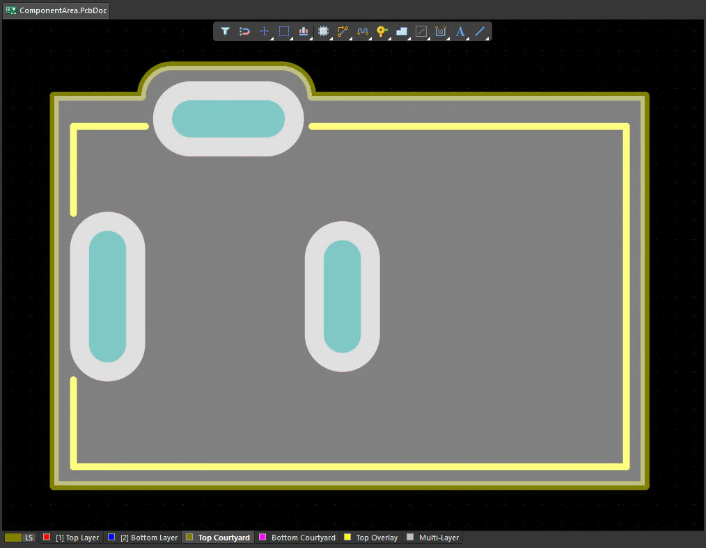
This rule specifies the minimum distance that components can be placed from each other. Component clearance checking includes the clearance between 3D models included as part of the component footprint. In the absence of 3D models, or when the Check clearance by component boundary rule constraint option is enabled, the objects in the component footprint are used instead.
Component clearance is calculated using accurate 3D meshing to define the shape and contour of the component through its associated 3D model. These can be embedded true 3D models, or extruded 2D shapes (formed from 3D Body objects). Using 3D models provides the greatest accuracy when it comes to clearance checking, particularly in the vertical direction with complex component shapes.
Constraints
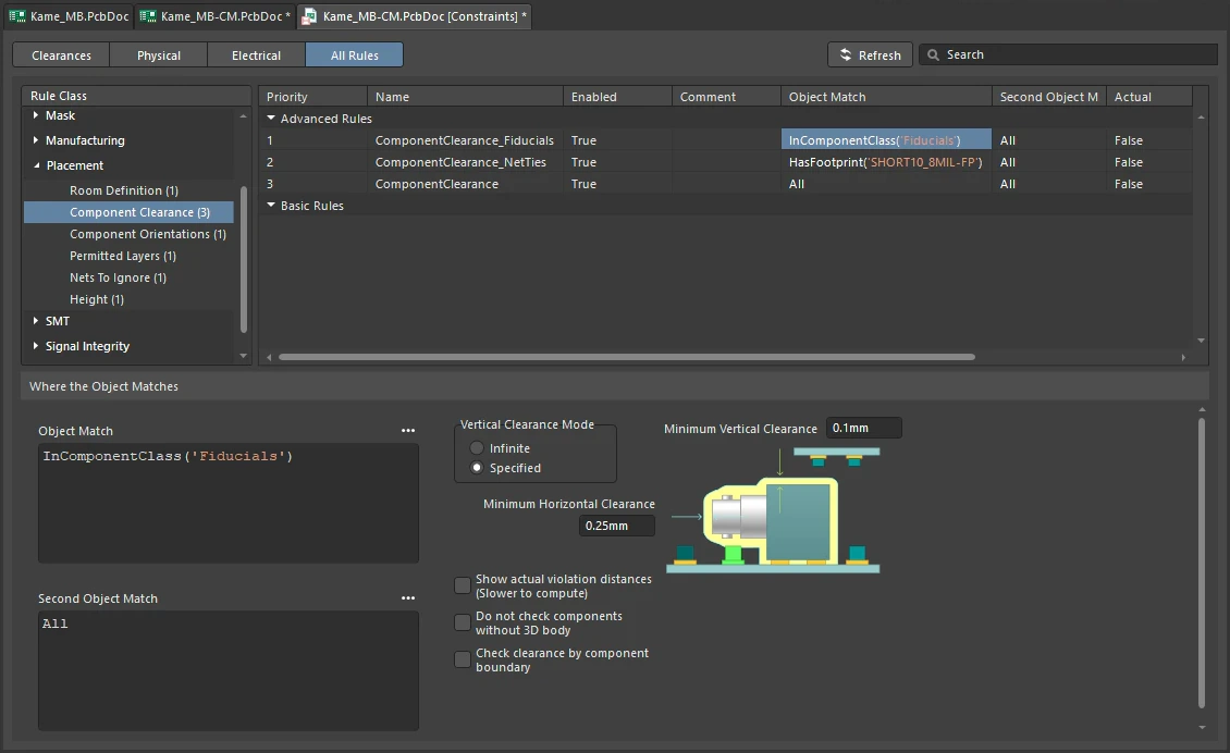
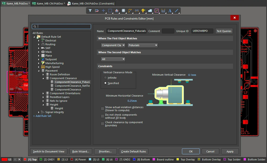
Component Clearance Constraints
| Default Rule | Required |
| Vertical Clearance Mode | Two modes for specifying vertical clearance are available:
|
| Minimum Horizontal Clearance | The value for the minimum permissible clearance, in the horizontal plane, between components placed in the design. This setting must be a value equal to or greater than zero. Enter a negative value to disable clearance checking for the components targeted by this rule. |
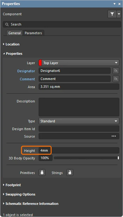
| Minimum Vertical Clearance | The value for the minimum permissible clearance, in the vertical sense, between components placed in the design. Enter a negative value to disable clearance checking for the components targeted by this rule. If a component includes a 3D model, it is the clearance above the model. If there is no 3D model, it is the clearance above the component's Height property ( |
| Show actual violation distances | Enable this option to show lines between the points of greatest violation between components. The failure distance is displayed at the line, which can be useful in determining the distance required to move an object to resolve the violation. |
| Do not check components without 3D body |
|
| Check clearance by component boundary |
|
| How are 3D models included? | The area that the component occupies on the fabricated board is defined by the component footprint. The component that is mounted on that footprint can be modeled using 3D Body objects. As well as modelling the component shape out of one or more 3D body objects, a 3D Body object can be used as a container into which a generic MCAD format model is imported.
|
Each component is made up from a collection of track, arc and pad objects placed on various layers. The basic approach the software uses to interpret this set of objects as a component is determined by an advanced option called
In terms of how the DRC system views the components:
|
|
| Wirebond wires | The Component Clearance rule checks for clearance violations between bond wires and other (non bond wire) objects in the 3D space ( |
| Rule Application | Online DRC and Batch DRC. |
 ).
 ).
 )
 ).
 ).
 ).
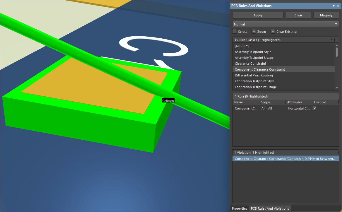 ).
Learn more about interpreting DRC violations.
Component Orientations
Default Rule: not required
The rule is not currently observed by the DRC tool.
Permitted Layers
This rule specifies the layers on which components can be placed.
Constraints
Permitted Layers Constraints
| Default Rule | Not required. |
| Permitted Layers | The layers permitted to be used when placing components. The following layer options are available:
|
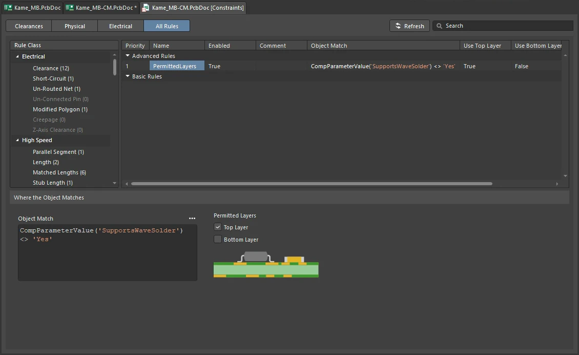
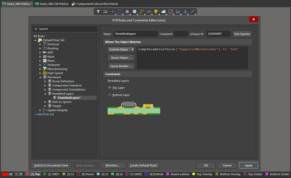
| Usage | The rule acts as a test when performing a Batch DRC, ensuring that targeted components have been placed on a permitted layer. To give an example of how this rule could be used to detect if a bottom-side component was suitable to pass through a wave solder bath:
Full Query: CompParameterValue('SupportsWaveSolder') <> 'Yes' Permitted Layers: the Top Layer constraint is enabled, with the Bottom Layer constraint disabled. This rule then checks that components that do not include the parameter SupportsWaveSolder = Yes are mounted on the Top Layer. If they are not, they are flagged as being in violation during Batch DRC. The advantage of this approach is that it detects both components that have the parameter/value SupportsWaveSolder = No, as well as components that do not include the SupportsWaveSolder parameter. |
| Rule Application | Batch DRC. |
Nets to Ignore
Default Rule: not required
The rule is not currently observed by the DRC tool.
Height
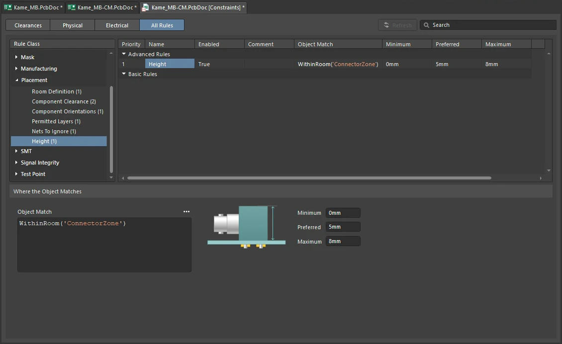
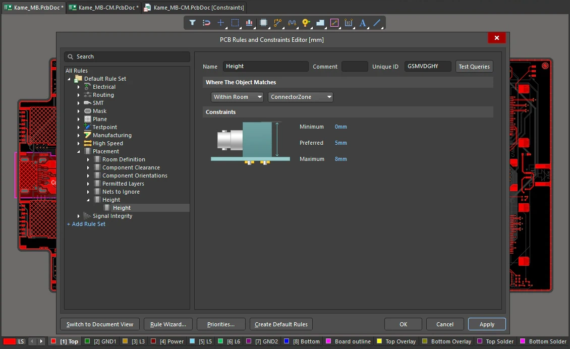
This rule specifies height restrictions for components placed within the design, based on either the height of the 3D model, or the Height property defined in the component footprint.
Constraints
Height Constraints
| Default Rule | Required |
| Settings |
|
| How the height is determined | The height of a component is defined by:
|
| Usage | Create a component class to use in the scope definition for a height rule, or constraint this to all components within a region of the board by defining a component room definition. |
| Rule Application | The Preferred setting is obeyed when displaying the board in 3D. The Minimum and Maximum settings are obeyed by the Online DRC and Batch DRC. |