Altium Designer includes capabilities to import design data from and export to popular formats such as STEP and Parasolid to exchange with MCAD tools.
Note that for supported MCAD packages, it is also possible to transfer the board and components directly between MCAD and ECAD using CoDesigner, Altium's ECAD-to-MCAD connectivity technology. Working through a connected Workspace, such as an Altium 365 Workspace, CoDesigner can push the board shape and placed components back and forth between your MCAD software and Altium Designer.
Learn more about Direct ECAD-MCAD Design with Altium CoDesigner.
STEP Files Import-Export Support
Altium Designer offers advanced capabilities for interacting with mechanical design systems and software (MCAD) through the active exchange of physical design data. The range of systems and interfaces that bridge the ECAD-MCAD domains also rely on standardized data formats such as the industry ratified STEP protocol (Standard for Exchange of Product model data), which provides an information-rich, clear text encoded file format for 3D model design data.
The STEP file format itself (*.step or *.stp) is defined in the ISO 10303-21 (International Organization for Standardization) specification for CAD data exchange and is supported by the majority of MCAD tools and systems. At the fundamental file exchange level, Altium Designer offers both export and import capabilities for 3D STEP files.
This provides the basis for the free exchange of high-quality, standardized 3D modeling data between software domains, which simplifies ECAD-MCAD design collaboration and enhances both the quality and accuracy of 3D model data. Note that both the STEP AP214 and the legacy AP203 formats are supported by Altium Designer – exported files are ISO-10303-21 -compliant (AP214).
See the ISO 10303-21 specification page.
Read information on the STEP file format.
Export STEP files
An important function in the data exchange relationship between the ECAD and MCAD worlds is the ability to port the PCB or Multi-board assembly into mechanical design software for the purposes of physical clearance checking. This is particularly crucial where the design is intimately matched with a product enclosure that also exposes PCB peripherals such as controls, switches, connectors, and displays.
In this case, the inherent universality and accuracy of the STEP file format allows comprehensive PCB modeling data to be transferred from Altium Designer to MCAD software with a high degree of confidence in the dimensional relationships. The MCAD designer can then import and place the PCB assembly 3D STEP model into the mechanical design to check and/or modify accordingly.
To access STEP file export capabilities in Altium Designer, the STEP and MBASTEP features must be enabled for your installation of Altium Designer. These features are enabled in Altium Designer by default. They can be enabled/disabled after installation.
For more information about changing installed core functionality, refer to the Installing & Managing page (Altium Designer Develop, Altium Designer Agile, Altium Designer).
Using the Exporter
An Altium Designer PCB document can be exported to the STEP file format. In an Outputjob file, click [Add New Export Output] and select an entry in the Export STEP menu. The export outputs can then be generated directly from the file or as part of the Project Release process.

Alternatively, select the File » Export » STEP 3D command from the main menus of Altium Designer's PCB editor. After launching the command, nominate a target file name and location.
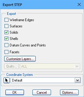
The Export Options dialog, accessed by double-clicking an added STEP export output or launching the File » Export » STEP 3D command, provides a range of selections, including options to determine which board objects will be included in the generated file.
 Exported STEP files displayed in an MCAD application, where the upper image file includes no pad holes or 3D bodies and the lower image file includes all objects.
Options and Controls of the Export Options Dialog
An incarnation of the Export Options dialog opens when you are exporting to a STEP, PARASOLID or VRML formatted file. Its content will vary slightly depending on the format and also whether export is being performed using a File » Export command, or a configured outputter as part of an Output Job file. Variations are highlighted below.
Board Options
Note that the fold amount defined by the
Fold State slider on the
PCB panel when configured in
Layer Stack Regions mode will become the default fold amount when the
Export Options dialog opens.
-
Skip Free 3D Bodies - enable to export without free 3D models.
-
Skip Hidden 3D Bodies - enable to export without hidden 3D models.
-
Export As Single Part - this option only applies when exporting to a STEP file. Check to export the STEP file as a single part or as one model per component. When this option is enabled, the STEP file will be saved as a part and not as an assembly.
Components With 3D Bodies
These options are only available when accessing the dialog through a File » Export command.
Select an option as to which components to include in the exported file. The options are designed to offer a choice between full and limited detail in order to speed up the export process and reduce file size.
-
Export All - select to export all components. This option is slower and increases the size of the exported file.
-
Export Selected - select to export only the selected components. This option is faster and reduces the size of the exported file.
Board cutouts are always included in the export.
Selecting specific components or holes to export is easier in 2D. If you want to export only the board, choose Export Selected and select nothing in the document. Non-PCB mounted, free-floating 3D bodies will also be included in the export. To not include them, use the Export Selected option without selecting the free-floating 3D bodies.
3D Bodies Export Options
The following options apply to components that have both extruded (simple) 3D bodies and STEP model 3D bodies assigned to them.
-
Prefer simple bodies - select to export the extruded (simple) 3D body version of the component.
-
Prefer generic 3D models - select to export the generic 3D body version.
-
Export both - select to export both extruded and generic 3D body versions.
If only extruded 3D bodies are available for components, they will always be exported.
Copper Export Options
These options are available only when exporting to PARASOLID format.
Use the following options to select your options for exporting copper.
-
Export Without Copper - select to export without copper.
-
Export Copper Only - select to only export copper.
-
Export Selected Only - select to export the copper objects belonging to the selected objects.
-
Export By Layer - select to export copper by layer. Use the drop-down to select one of the following layers:
-
Top Layer
-
Mid-Layer 1
-
Mid-Layer 2
-
Bottom Layer
Choose this mode when you need to export only the copper objects on the chosen layer, including the thru-hole pad and via rings on that layer.
-
Export All - select to export all.
If you enable the Export Copper Only, Export Selected Only, or Export By Layer options, you will only export copper objects, despite having non-copper export options selected. If you Export Without Copper or Export All, you will see the board and components, depending on the other component options you have selected.
Pad Holes
The following options are available only when the dialog has been accessed through a File » Export command.
Use the following options to select which holes to include in the exported file. The options are designed to offer a choice between full and limited detail in order to speed up the export process and reduce file size.
-
Export All - select to export all holes in the board. This option is slower and increases the size of the exported file.
-
Export Selected - select to export only the holes that are selected. This option is faster and reduces the size of the exported file.
The following options are available only when the dialog has been accessed through an OutJob file.
-
Export Mechanical Component Pad Holes - check this box to export any mechanical component pad holes.
-
Export Electrical Component Pad Holes - check this box to export any electrical component pad holes.
-
Export Free Pad Holes - check this box to export any free pad holes.
Component Suffix
Use the following options to specify the suffix of the exported components.
-
None - no suffix will be applied to components.
-
Board file name - use generic 3D filename as the component suffix.
-
Custom - select to customize the component suffix. Enter the custom suffix in the text box.
Notes on Exported files
-
If the Export Selected options (3D Bodies and Pad Holes) have been enabled in the Export Options dialog but no objects are currently selected in the PCB editor, then the generated STEP files will not include any of those object types.
-
The board is always exported. To exclude all components (only export the board), enable the Export Selected option, with no components selected.
-
If you only want to export select components, it is generally easier to select them in 2D display mode.
-
When the Export as Single Part option is selected, the generated STEP model will be saved as a single part, rather than an assembly of component models. This simplifies the exported STEP model but prevents individual components from being selected in the receiving MCAD application.
-
STEP files generated by the Export 3D feature position the model graphic relative to the origin point in the source PCB design. The software used to import that file may or may not respond to the included location instruction – if the imported model is not displayed, it may be off screen at the current zoom level.
-
Free 3D Bodies are additional 3D models placed in the PCB editor, such as the enclosure.
-
The 3D Bodies Export Options apply to 3D bodies/models added to the component footprints in the PCB library editor. The term simple bodies refers to extruded, cylindrical or spherical 3D Body objects.
-
In the STEP file, each component is identified by its designator. If the MCAD designer needs to import multiple boards into a single MCAD file there is likely to be designator clashes, to avoid this include a Component Suffix.
-
The Export Folded Board option only functions if there bending lines defined in the design. To export the board partially folded, before running the Export command, configure the fold amount using the Fold State slider in the Layer Stack Region mode of the PCB panel. The value defined will automatically be applied in the Export Options dialog.

A partially folded rigid-flex board, exported from the PCB editor and imported into the Rhinoceros 3D MCAD design software.
-
If you do not have access to mechanical drawing/viewing software, the exported STEP file can be checked by importing it back into a placed 3D Body object in Altium Designer.
An Altium Designer Multi-board Assembly document can be exported to the STEP file format. Use the MBA Export STEP entry of the [Add New Export Output] menu in an Outputjob file or select the File » Export » STEP 3D command from the main menus of Altium Designer's Multi-board Assembly editor.
Save from the IPC Component Wizard
The automated IPC Compliant Footprint Wizard, which creates an IPC-compliant footprint in the PCB Library editor, provides the additional option of saving (and previewing) the generated footprint model as a 3D STEP file. The STEP based model can be embedded in the generated IPC-compliant footprint and also saved as a *.step file in a nominated location, where the latter option will allow the 3D model to be reused or distributed as needed.
The IPC Component Wizard is launched from the PCB footprint editor (Tools » IPC Compliant Footprint Wizard) and the STEP export option enabled in the wizard’s penultimate Footprint Destination page. The generated STEP file model will accurately match the component dimensions that have been entered in the wizard.
 Along with the option to generate and embed a STEP model for the component, the wizard also allows this to be saved as a STEP 3D model file.
Import STEP Files
Import into the PCB or PCB Footprint
STEP files can be imported and used in Altium Designer through two distinct approaches, both of which use the same mechanism. The approach used is essentially dependent on how a STEP file will be applied in a design:
-
A STEP file that represents mechanical elements of the final product design, such as an enclosure generated by an MCAD application, is generally imported into the PCB layout.
-
A STEP file that represents a 3D component body (downloaded from the internet or created locally) is generally imported into a PCB footprint.
Within both the PCB and PCB footprint domains in Altium Designer, STEP files are imported into a dedicated 3D Body object that is placed and aligned as required. Refer to the 3D Body Object Placement section to learn more.
Exporting the Enclosure and Board Shape from MCAD for Use in Altium Designer
A common approach is for the mechanical designer to develop an initial concept model, so everyone involved can get a sense of what the product will look like. From there the mechanical designer refines the enclosure design and defines the initial board shape.
That enclosure and board shape can be passed over to the ECAD designer, by saving it out of the MCAD tool in the STEP format and placing it into the PCB editor design space. Altium Designer includes a command that will redefine the ECAD board shape directly from the MCAD board shape.
STEP is a complex and highly detailed file format. To maximize the success of transferring design data, keep the following in mind:
-
The board shape can be exported inside the enclosure, as long as it is a separate sub-assembly. If this has been done, you can redefine the ECAD board shape from the mechanical definition with a few clicks in the PCB editor.
-
Use the AP214 format whenever possible.
-
Use a surface or solid geometries option, if available.
, and PTC Creo (formerly Pro/E) (second image).")
Suitable export options for SolidWorks (first image), and PTC Creo (formerly Pro/E) (second image).
Import into the Multi-board Assembly
A STEP model can be added to the active Multi-board assembly document using the Design » Insert STEP Part command from the main menus.
Parasolid Files Import-Export Support
Export Parasolid Files
An Altium Designer PCB document can be exported to the Parasolid file format. In an Outputjob file, click [Add New Export Output] and select an entry in the Export PARASOLID menu. The export outputs can then be generated directly from the file or as part of the Project Release process.

Alternatively, select the File » Export » PARASOLID command from the main menus of Altium Designer's PCB editor. Options for the export are defined through the Export Options dialog.
Export of a PCB into Parasolid format uses Parasolid version 35.1.
When exporting a panelized PCB (Embedded Board Array) to Parasolid format, a Route Tool Path is cut through all board layers in the exported file, and cavities and board cutouts from a source board are taken into account on the panelized PCB.
Import Parasolid Files
Within both the PCB and PCB footprint domains in Altium Designer, Parasolid files are imported into a dedicated 3D Body object that is placed and aligned as required. Refer to the 3D Body Object Placement section to learn more.
SolidWorks Part Files Import Support
Within both the PCB and PCB footprint domains in Altium Designer, SolidWorks Part files (*.sldprt) are imported into a dedicated 3D Body object that is placed and aligned as required. Refer to the 3D Body Object Placement section to learn more.
A 3D model that is in SOLIDWORKS Parts File (*.SldPrt) format that is created from SOLIDWORKS versions 2022, 2023, 2024, or 2025 can be imported when using a generic 3D model with a 3D Body object.
VRML Files Export Support
An Altium Designer PCB document can be exported to the VRML file format. In an Outputjob file, click [Add New Export Output] and select an entry in the Export VRML menu. The export outputs can then be generated directly from the file or as part of the Project Release process.

Alternatively, select the File » Export » VRML command from the main menus of Altium Designer's PCB editor.
IDF Files Import-Export Support
-
Altium Designer supports IDF format data up to version 3.0.
-
To access IDF file import/export capabilities in Altium Designer, the IDF feature must be enabled for your installation of Altium Designer. This feature is enabled in Altium Designer by default. It can be enabled/disabled after installation.
For more information about changing installed core functionality, refer to the Installing & Managing page (Altium Designer Develop, Altium Designer Agile, Altium Designer).
Export IDF Files
An Altium Designer PCB document can be exported to the IDF file format. In an Outputjob file, click [Add New Export Output] and select an entry in the Export IDF menu. The export outputs can then be generated directly from the file or as part of the Project Release process.

Alternatively, select the File » Export » IDF Board command from the main menus of Altium Designer's PCB editor.
The File Export IDF dialog provides controls to configure the properties of exported IDF files. The dialog is accessed by double-clicking an added IDF export output in the Outputjob file or by clicking Save in the Export File dialog after selecting File » Export » IDF Board.

The File Export IDF dialog
Options and Controls of the File Import IDF Dialog
-
Version - selected the appropriate version.
-
Units - select the appropriate units: Imperial or Metric.
-
Exported Drilled Holes
-
All - select to export all drilled holes.
-
Selected - select to export only the selected drilled holes.
-
Larger Than - select to export only drilled holes that are larger than the size specified in the text box.
-
Exported Sections - enable the checkbox of the desired sections.
-
File Compatibility
-
Replace '.' With '_' In Component Names - check this box to replace a period character with an underscore character within names of components.
-
Replace Blank Component Fields With - enter text for which you want to replace blank component fields.
-
Override Part Number With - enable to override part numbers during file generation. From the drop-down menu, you can choose to override the Part Number with any of the following options. The drop-down menu is available only when the Override Part Number With option is enabled.
-
Comment
-
Item HRID
-
Revision HRID
-
Library REF
-
<Enter Schematic Parameter>
For <Enter Schematic Parameter>, type the desired schematic parameter on which you want to base the component names in-between the brackets.
-
Component Outlines From Multiple Component Bodies
-
Use Bounding Component Body - select to use a bounding component body.
-
Create Sub Components - select to create sub-components.
-
Generated Files - exporting IDF files will generate two files – one containing information about the physical size and shape of the PCB and positions of components, the other containing information about each component including name, size, and shape. These are typically referred to as the board and library files, respectively. Different CAD packages use different file extensions for the board and library files. Use the drop-down to select the board file and library file extensions of the generated files. Choices include:
-
.brd and .pro
-
.brd and .lib
-
.emn and .emp
-
.bdf and .ldf
-
.idb and .idl
-
.idf and .lib
-
Use Unicode - check this box to use the Unicode standard for text in the generated files.
Import IDF Files
To import an IDF file into the active PCB document, select the File » Import » IDF Board command from the main menus of Altium Designer's PCB editor. After selecting the command, the File Import IDF dialog that allows you to configure the properties of imported IDF files will open.

The File Import IDF dialog
Options and Controls of the File Import IDF Dialog
-
Offsets - enter the desired offset distances for X and Y in the text boxes.
-
Board File Import Options - enable the checkbox of the items you want to import.
-
OK - click to initiate the import process.
IDX Files Import-Export Support
As more and more electronic products involve both electrical and mechanical components, and product release cycles get shorter, there's a real need for stronger collaboration between the ECAD and MCAD domains. But that collaboration isn't always smooth. The electrical designer and mechanical designer often send emails back and forth, or have to dabble in each other's respective design tools - something that leaves them treading a little water, and far removed from their established comfort zones. One solution is to use a method of collaboration that enables the two to graphically communicate ideas and proposals for change, without leaving their trusty working environments. Such a method is provided through an XML-based exchange file format - IDX (Incremental Design EXchange format).
With this intermediate exchange file (*.idx), an electrical designer can export only changes to the board design that are needed (and of value) by the mechanical designer. Conversely, the mechanical designer can float change proposals back to the electrical designer, who can then import those changes back into their design.
Support for this standard of collaboration between ECAD and MCAD domains is available in Altium Designer, courtesy of the MCAD IDX Exchange extension. This extension allows you to incrementally exchange data between Altium Designer and mechanical CAD applications (such as SOLIDWORKS), using the IDX exchange format. Functionality includes support for change requests, as well as the transfer of Cu geometry.
-
Altium Designer supports IDX format version 2.0 only.
-
To access IDX file exchange capabilities in Altium Designer, the MCAD IDX Exchange software extension must be installed. This extension can be installed or removed manually.
For more information about managing extensions, refer to the Extending Your Installation page (Altium Designer Develop, Altium Designer Agile, Altium Designer).
-
Note that to use IDX file exchange capabilities in Altium Designer, you must have an active Altium subscription.
Initiating the Baseline File for Collaboration
Collaboration can be kicked off from either direction - either the electrical designer creating the initial IDX file, or the mechanical designer doing the honors. If the electrical designer does so, the file created is called the ECAD Baseline file (ECAD Baseline.idx), which is subsequently made available to the mechanical designer. If the mechanical designer does so, it is called the MCAD Baseline file (MCAD Baseline.idx), which is subsequently made available to the electrical designer.
Exporting from Altium Designer (ECAD Creation of Baseline)
From within Altium Designer, the main interface for collaboration is the MCAD IDX Exchange panel, which is accessed by clicking the  button at the bottom-right of Altium Designer when the PCB editor is active then selecting the MCAD IDX Exchange entry from the menu.
The panel can also be accessed using the MCAD IDX Exchange command from the main Tools menu.
To initiate collaboration, click the Export Baseline button. You will be presented with the Export EDMD Baseline dialog, which offers options, including the export of copper objects.
Exporting copper makes the IDX files much bigger and slower to process on the MCAD side. In addition, the IDX technology does not support change detection for copper objects.
 Initiate collaboration from within Altium Designer by creating the ECAD Baseline.
Importing to Altium Designer (MCAD Creation of Baseline)
If the baseline file has been created on the MCAD side, it can be imported into Altium Designer using the File » Import » MCAD IDX Baseline command. The Import MCAD Baseline dialog will open. Use this to browse to and specify the MCAD Baseline file (MCAD Baseline.idx), and the PCB document into which proposed changes are to be synchronized.
 Accept collaboration from within Altium Designer by importing the MCAD Baseline.
-
Input MCAD Baseline File - click
 to browse for and select the desired IDX file to be imported.
-
Output PCB File - click to browse for and select the desired PCB file into which proposed changes are to be synchronized.
Once the MCAD Baseline IDX file has been imported, collaboration proceeds through the MCAD IDX Exchange panel.
Collaboration Folder
When initiating collaboration from Altium Designer (creating the IDX Baseline file), a collaboration folder will be created under the original board design project. The folder is named using the PCB document name in the form <PCBDocumentName>.PcbDoc_EDMD. The folder will contain two files:
-
AD_EDMD_State.xml
-
ECAD Baseline.idx
Quickly access the generated folder from the MCAD IDX Exchange panel by clicking the Show In Explorer control (available only after initial export) or by clicking the  button then choosing the Open Collaboration Folder entry from the associated menu.

Creation of the folder and baseline file.
Synchronizing Changes
The MCAD IDX Exchange panel provides controls for keeping changes synchronized between the ECAD and MCAD domains. Changes are proposed through IDX Changes files:
-
If the mechanical designer has proposed changes and sent them across in a new IDX Changes file, the panel allows those changes to be received (imported) into the PCB design for consideration.
-
If changes have been made to the board, the panel can detect these changes (except copper changes) and list them, ready for export to an IDX Changes file that is subsequently made available to the mechanical designer.
Detecting and Exporting Board Changes
If you make a change to the PCB document, such as removing a component, that change can be detected by clicking the  button at the top of the MCAD IDX Exchange panel. The detectable changes will be listed in the Board Changes region of the panel, in terms of:
-
Object - for example, the component designator.
-
Change - for example, Removed for a component that has been removed from the design, or Added for one that has been added.
-
Status - this will be Proposed since the change is originating on the ECAD side.
-
Proposition Comment - a note to explain the change to the mechanical designer. Enter this as required.
 Detecting changes to the board.
Once all changes have been made, detected, and proposition comments added, those changes can be exported using the  button. This will create an IDX Changes file (ECAD Changes n.idx).

With proposed changes to the board made, export to create an IDX Changes file to send those proposed changes to the mechanical designer.
It is now up to the mechanical designer to import and view the change proposals on their side. They will then either accept or reject each proposed change in turn, and send back their response in an IDX Response file (MCAD Response n.idx). Once this is received, import the response using the  button. To apply the changes in the response file, click the
  button, which will generate an IDX Response file from the ECAD side back to the mechanical designer (ECAD Response n.idx).
This "handshaking" ensures that both parties are synchronized with the changes made.
To abandon the proposed changes, click the

button; the
Board Changes list will be cleared.
Importing Changes
If the mechanical designer is proposing changes, those changes will be proposed in an IDX Changes file (MCAD Changes n.idx). Import the changes using the panel's  button. The changes will be listed in the Changes from Mechanical CAD region of the panel in terms of:
-
Object - for example, the component designator.
-
Change - for example, Moved for a component that has been moved within the design.
-
Status - this will be Proposed since the change is originating on the MCAD side.
-
Proposition Comment - a note to explain the change to the electrical designer.
 Changes proposed by the mechanical designer, imported into the panel.
It is now up to you, as the electrical designer, to view and either accept or reject each proposed change in turn. To accept a proposed change, check its associated Accept check box. To reject, leave this unchecked. You also can enter a response in the respective Response Comment field.
Once all proposed changes have been accepted/rejected, click the button. The accepted changes will be applied to the PCB document and an IDX Response file (ECAD Response n.idx) will be created, ready to send back to the mechanical designer.
Resetting Collaboration
To completely reset collaboration on the project, click the button then choose the Reset Collaboration entry from the associated menu. All current entries in the panel will be cleared and all files in the collaboration folder will be deleted. This puts you back at square one, ready to export a baseline file, or import one, and start collaboration afresh.
Note that any applied changes to the design prior to a reset will remain.
