
Harness Connector Type Properties
Created: April 08, 2021 | Updated: April 08, 2021
| Applies to version: 4
This document is no longer available beyond version 4. Information can now be found here: Harness Connector Type Properties for version 5
Parent page: Harness Connector Type
Schematic Editor object properties are definable options that specify the visual style, content and behavior of the placed object. The property settings for each type of object are defined in two different ways:
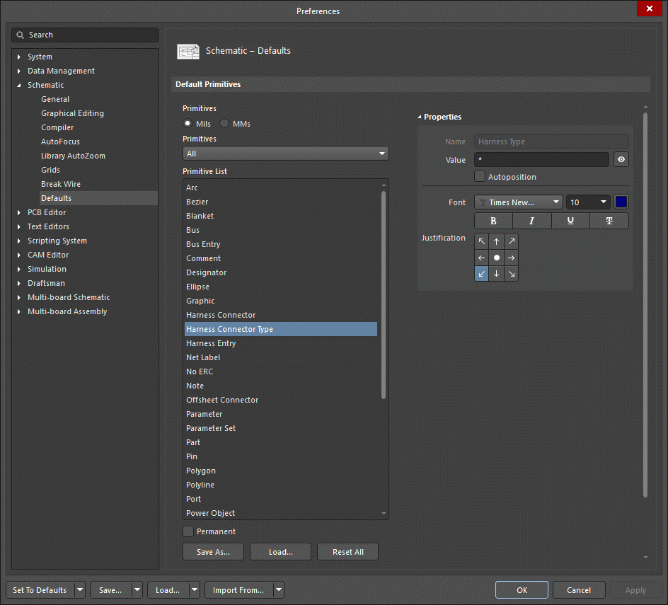
- Pre-placement settings – most Harness Connector Type object properties, or those that can logically be pre-defined, are available as editable default settings on the Schematic - Defaults page of the Preferences dialog (access from the
 button at the top-right of the design space). Select the object in the Primitive List to reveal its options on the right.
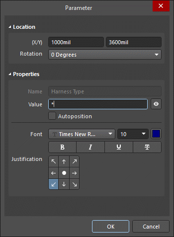
- Post-placement settings – all Harness Connector Type object properties are available for editing in the Parameter dialog Properties panel when a Harness Connector Type is selected in the design space.
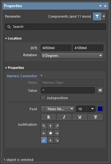
Location (Properties panel only)
- (X/Y)
- X (first field) - the current X (horizontal) coordinate of the reference point of the object, relative to the current design space origin. Edit to change the X position of the object. The value can be entered in either metric or imperial; include the units when entering a value whose units are not the current default.
- Y (second field) - The current Y (vertical) coordinate of the reference point of the object, relative to the current origin. Edit to change the Y position of the object. The value can be entered in either metric or imperial; include the units when entering a value whose units are not the current default.
- Rotation - use the drop-down to select the rotation.
Properties
- Harness Connector - the harness connector associated with this object.
- Name - displays the name.
- Value - displays the actual filename text. Use the eye icon to show/hide the Value.
- Autoposition - check to enable auto-positioning, meaning that the text will remain in the chosen position as the component is moved and rotated.
- Font - use the controls to configure the font, font size, color, and special settings such as bold and underlines.
- Justification - select the desired justification of the text.