KB: Import a mechanical outline to PCB
Solution Details
The best method of defining the board shape from a mechanical drawing or a 3D model is to import the file and then redefine the board shape from that file. To do this:
For a 3D model
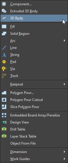
1. Place the 3D model on the PCB by: Place » 3D Body. Then select the model.
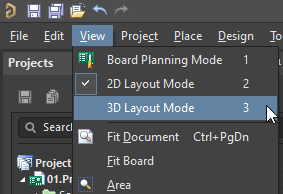
2. Enter 3D mode, by going to View » 3D Layout Mode
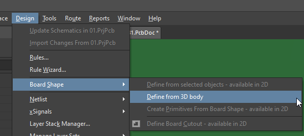
3. While in 3D Mode, go to Design » Board Shape » Define from 3D Body
4. Select the 3D model
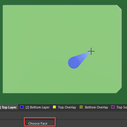
5. Choose the Face of the model that you want to become the Board Shape
6. Set Options for the new board shape
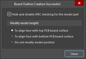
For a mechanical drawing
1. Import the file, which needs to be in DXF or DWG format by going to File » DXF/DWG
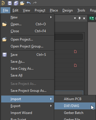
2. Select the mechanical drawing you want to import
3. Assign the scale to match the size/units of the drawing
4. Mapped the layers of the drawing to a mechanical layer on the PCBDoc
5. Select OK to import
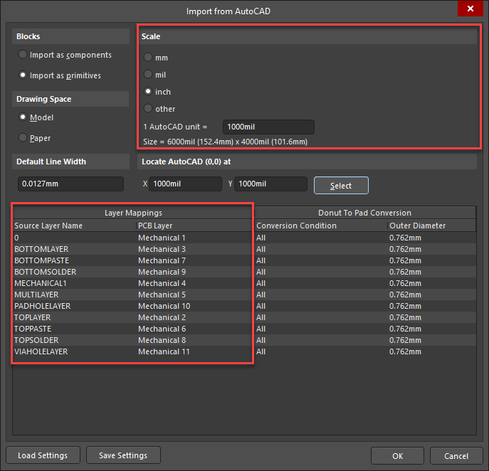
6. With the outline imported, move it to where you want the board to be.
7. Select all of the lines that make up the outline, then go to: Design » Board Shape » Define from Selected Primitives

8. This should create the board shape based on the outline
Here is documentation on Defining the Board Shape:
Importing an Outline to Use for the Board Shape
