
ブラウザベースのインターフェースを探る
In addition to connecting to your Enterprise Server through Altium Designer – interfacing to it through the Explorer panel and Components panel (for direct interaction with its components) – you can also connect to it through a dedicated browser interface. In fact, connection in this way is more than just a connection to the server itself. Rather it is a connection into the server platform, with access to management interfaces for the various services available as part of the wider Enterprise Server installation. Indeed with some of these services, your only interaction with them is through this browser-based interface.
Accessing the Interface
To access your local Enterprise Server through its browser interface, use a preferred external browser and type the address for the Enterprise Server in one of the following formats:
-
http://<ComputerName>:<PortNumber> -
http://localhost:<PortNumber>– if accessing from the same computer on which the Enterprise Server is installed.
(e.g. http://designerhome:9780, or http://localhost:9780, for an Enterprise Server installed using the default port assignment). You will be presented with a Sign-in page.
Sign in through the browser interface using the same Enterprise Server credentials used to connect through Altium Designer. For a newly installed Enterprise Server there is a default administrative user with the credentials:
- Username: admin
- Password: admin
 ).
).What's Provided?
The interface provides a number of key technologies and services and can be coarsely divided into two groupings, as shown in the following image and listed thereafter.

The overall browser interface can be divided into two distinct sets of interface elements – those accessible in general by all users of the Enterprise Server and those accessible only by Enterprise Server Administrators.
-
Interface elements that can be accessed by any Enterprise Server user. To access a page click on its name within the left-hand navigation tree.
-
Interface elements that can only be accessed by an Enterprise Server Administrator. A user is bestowed administrative powers by membership to the group Administrators. To access a page, choose the required entry within the Admin section of the left-hand navigation tree.
At the far right of the banner area, at the top of the interface, an entry reflects the user that is currently signed into the Enterprise Server, along with a picture (if defined) and the name of the server.
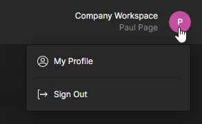
The drop-down menu associated with the entry provides the following controls:
-
My Profile – accesses the Edit User window with which the signed-in user can make changes to their own user profile. This is the only way that a non-admin user can make changes, since they do not have access to the Admin – Users page of the interface.
-
Sign Out – signs you out of the Enterprise Server interface.
General Access Interface Elements
The following sections summarize the elements of the Enterprise Server's browser interface that can be accessed by all users of the Enterprise Server – both administrators and standard users.
Projects
Related page: Workspace Projects
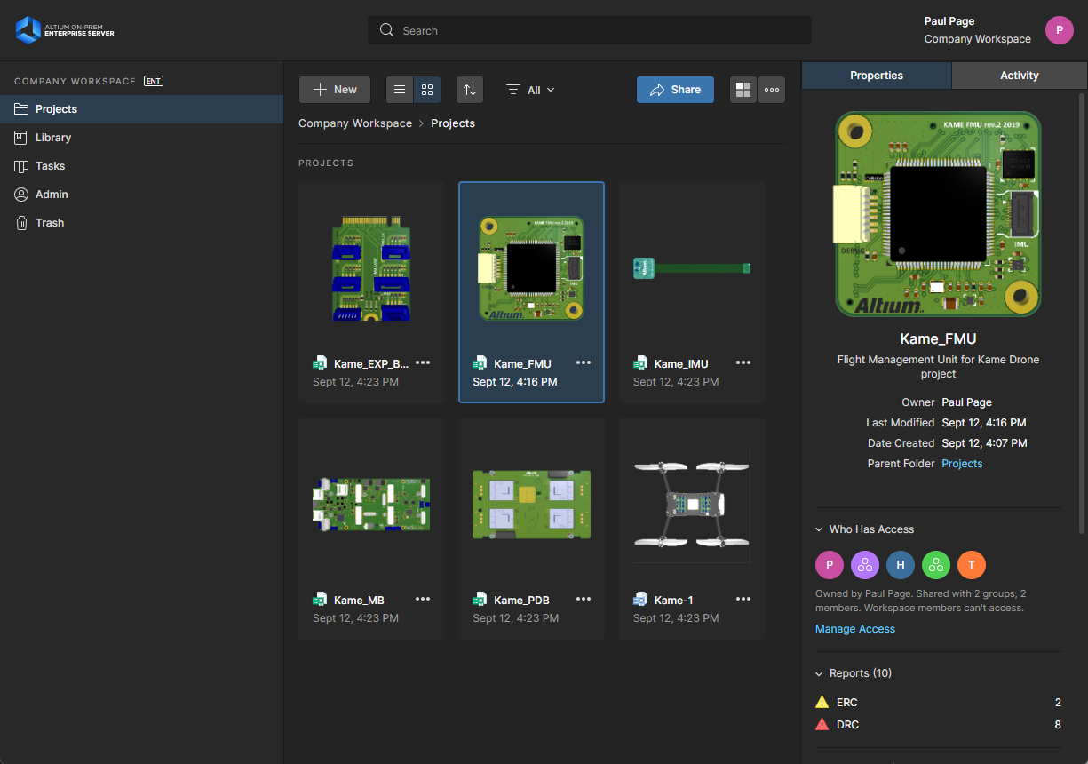
This page provides the interface to the Projects service, to create and manage projects in a central location, in a CAD-centric way, and share those projects for team collaboration as required. The page lists all projects that have been made available to the Enterprise Server and which are shared with the currently signed-in user. Workspace projects target the development stage of the project lifecycle, simplifying the creation and ongoing workflow for version-controlled projects. From here you can create new projects and open and manage existing ones. From this interface a project can also be shared, or rather its access permissions configured.

Centralized design project management – all part of your Enterprise Server installation.
You can also access a detailed, CAD-centric view of the project, opened by selecting the required project, clicking the ![]() control above the listing of projects, and choosing the Open entry on the associated menu. Alternatively, double-click directly on the required project entry in the list (or click on its name). The Projects Management page for that project opens in a new browser tab incorporating the CAD-centric interface, which offers Design, Supply, Manufacture, Activities and History view options:
control above the listing of projects, and choosing the Open entry on the associated menu. Alternatively, double-click directly on the required project entry in the list (or click on its name). The Projects Management page for that project opens in a new browser tab incorporating the CAD-centric interface, which offers Design, Supply, Manufacture, Activities and History view options:
-
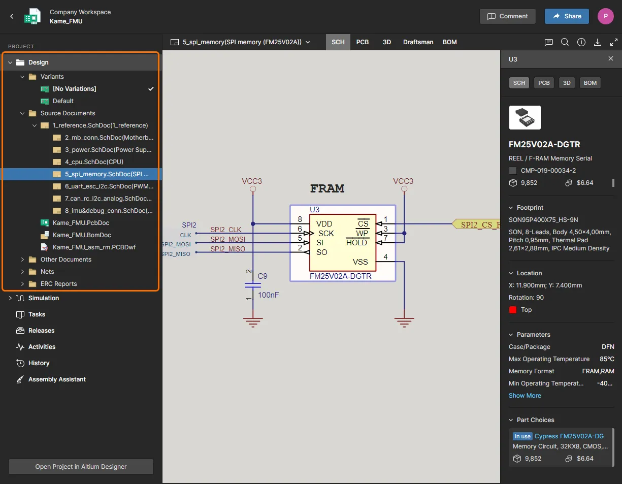
Design – display and navigate source project design documents, view design object properties and place review comments. This view uses the Web Viewer interface to present your design across five distinct data sub-views, to show the source schematic(s), board in 2D, board in 3D, Draftsman document and Bill of Materials respectively. This view is for the latest version of the source project data, rather than a specified release from that project, and so could be considered to be a work-in-progress (WIP) view. You can review both the base design and any defined variant thereof.
-
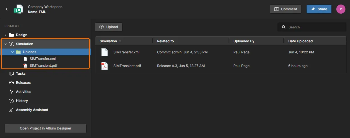
Simulation – allows you to upload circuit simulation results files that will be associated with the current project or project Release. The files are effectively attached to the project, which allows members of the Workspace to inspect and/or download simulation results documents that relate to the currently open project. See Management of a Specific Project for more information.
-
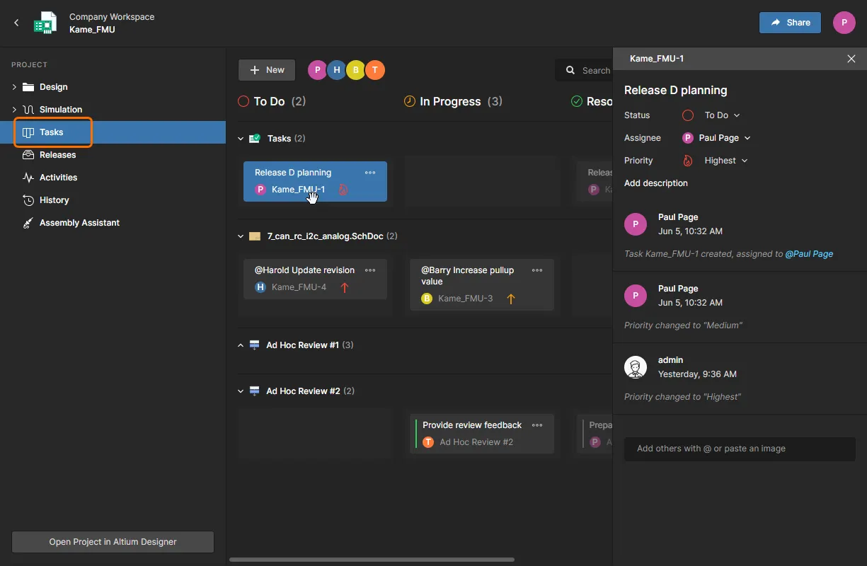
Tasks – allows you to access and manage the job activity requests (Tasks) that apply to the currently open design project. Tasks are presented in a Kanban board flow style, with their progress state (
ToDo,InProgressandResolved) arranged as Task rows. One row is reserved for General Tasks, and each remaining row applies to Tasks for a specific project document. The latter is populated with Tasks that are associated with the open project, and are created when a project Comment is assigned to a particular user (Workspace member), or when an active Process requires user action (such as completing a step in a design Review workflow). You also have the option to create a General Task from the New button – these Tasks apply to the current project but are not associated with a project Comment or document.See Working with Tasks for more information on general, comment-derived, and workflow-generated Tasks.
-
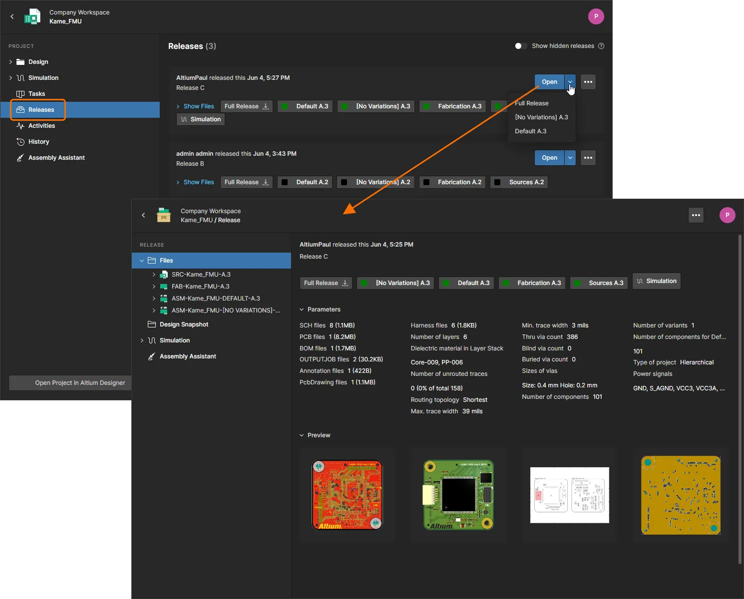
Releases – view the releases for the project. Access is provided for opening the full release data, or a specific assembly package, which will be presented on a separate tab through a Manufacturing Portal. From this portal, you can view and navigate the released file data, inspect the BOM, and view and comment on the snapshot of the design itself; the source for that released data. From either the Releases view, or through the Manufacturing Portal for a specific release, you'll have access to controls for downloading manufacturing data at various levels of granularity (from full data set(s) to individual generated output files).
-
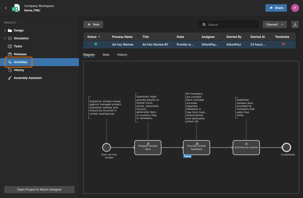
Activities – search, view and access project activity themed processes (active or closed) that apply to the selected project, such as design reviews. Click on an entry for a process to view a diagram of its underlying workflow (on the Diagram sub-view below the list), showing what needs to happen for the process to be completed, and where that process is at, along its flow, in terms of who now has a task to perform to move the process along. The Data sub-view shows all pertinent data for the process. For a design review process for example, this can include the project and its data set, the review type, people involved in the review, and any additional attachments. The History sub-view shows a history of actions taken along the process's workflow.
-
History – browse a progressive timeline of major events relating to the project, including its creation, commits, releases, clones and MCAD exchanges. Each time a supported event happens in association with the project, that event is added to the timeline as a dedicated tile with various actions supported where applicable. Detailed Schematic comparisons and BOM comparisons are available between commits and/or releases. For release events, you also have the ability to compare Gerber data between releases.
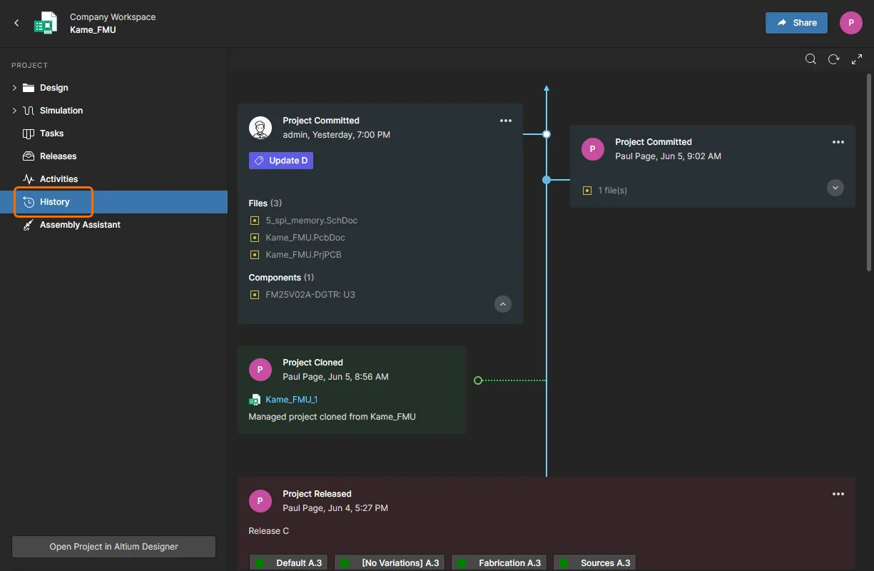
For more information on using this view, see Project History.
-
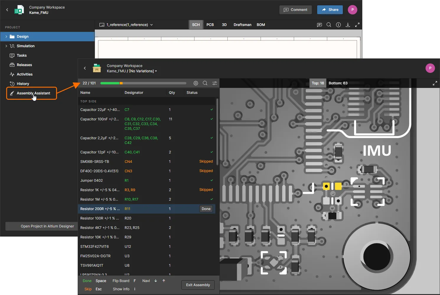
Assembly – work with the interactive Assembly tool to check and progress through the board assembly process. The tool brings together the project's detailed BOM data and its 2D/3D assembly view to present an interface that provides the required set of graphical and component part information for stepping through the assembly process. See the Assembly Assistant page for more information.
Components
Related page: Workspace Components
This page, accessed by selecting Library in the navigation tree, gives you convenient access for browsing all of the Workspace library components that are currently stored within your Enterprise Server. You are able to see, at-a-glance, what (and how many) components you currently have at your disposal (and gain detailed information about each and every component).
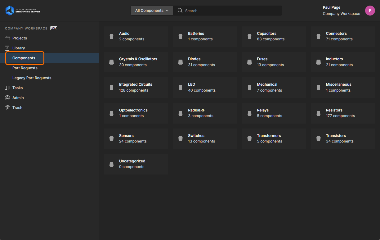
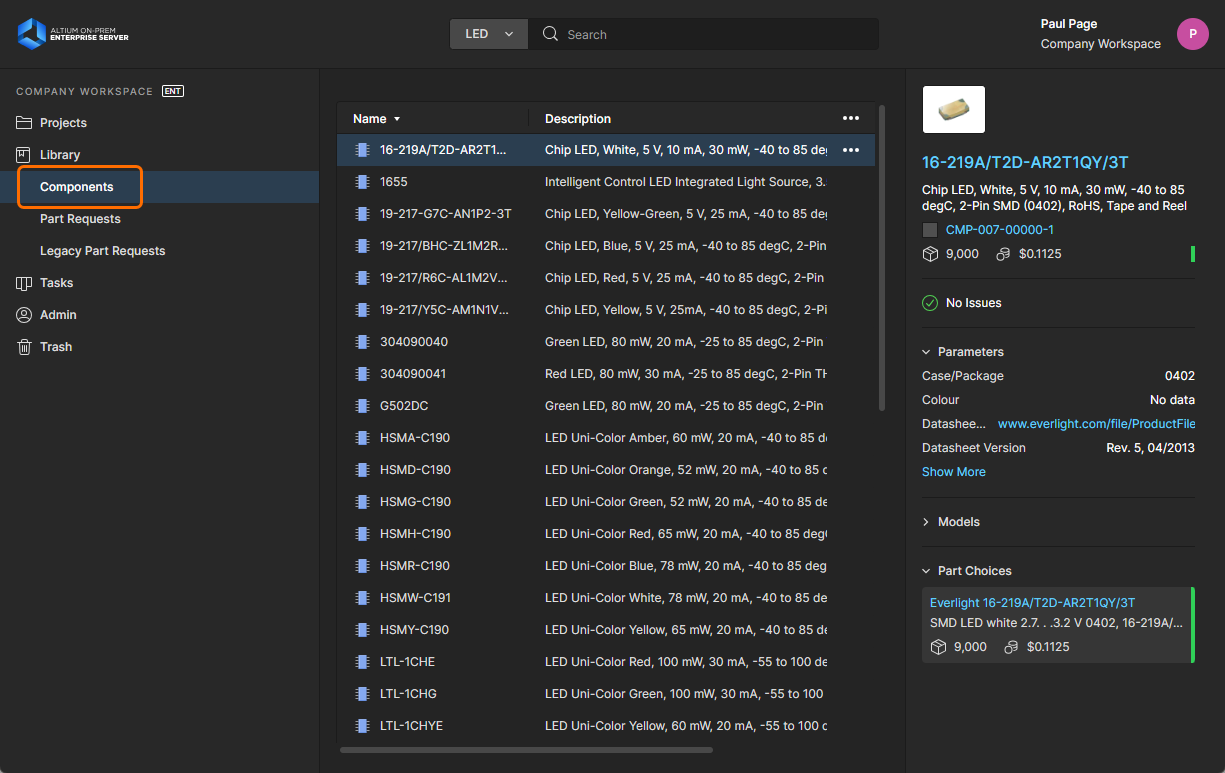
When the page is first accessed this region presents a tiled array of the various component types, along with the total number of existing components of each type. From here you are able to drill down to see individual components and get detailed information about them.
Part Requests
Related pages: Process-based Part Requests, Creating & Managing Processes
This page (Library – Part Requests) enables you to create and manage requests for new components. A designer can simply put in a request for one or more parts to be created, using predefined Part Request process workflows that have been defined for the company, and get notified when that request has either been rejected (and why), or processed and the component(s) made available. The requestor supplies as much key information to support their request as possible (manufacturer and part number(s), description(s), any relevant datasheet (PDF or URL)). Stub Component Items can even be created that the person assigned to the part request can then run with (and finish off).
A single predefined process definition for Part Requests is activated for use out-of-the-box (New Part Request). This can be found on the Part Requests tab of the Processes page of the browser interface. Use this, modify it, or create your own as required, to suit the needs of making part requests within your company. In addition five more sample process definitions are available – New Part Request Assign, New Part Request Multiple Tasks, Part Request with PLM Part Create, Part Request with lifecycle change, and New Part Request Notify 3rd party. These cannot be activated and used as is. Each of these is therefore more like a 'template' – edit to suit your company's requirements, then name and save as a new process definition which you can then activate and use, along with all other definitions in the Part Requests process theme.

Create and manage requests for new parts through the Part Requests area of the Enterprise Server's browser interface. Each part request follows a chosen process workflow. In this image, you can see the associated flow depicted graphically on the Diagram tab, including indication of where in the process the request has reached.
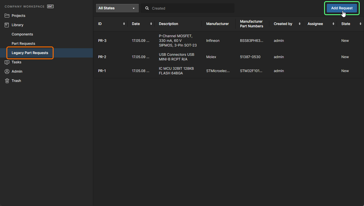
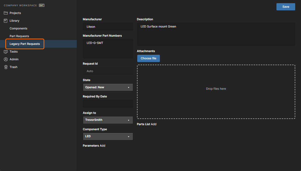
Legacy Part Requests
Related page: Part Requests
This page (Library – Legacy Part Requests) enables you to create and manage requests for new components using the legacy Part Request functionality. An engineer can simply put in a request for one or more parts to be created and get notified when that request has either been completed, and the component(s) made available, or rejected (and why). The requestor supplies as much key information to support their request as possible (manufacturer and part number(s), description(s), any relevant datasheet (PDF or URL)). Stub Component Items can even be created that the librarian can then run with (and finish off).
Tasks
Related pages: Working with Tasks, Web Viewer – Commenting Window
This page view allows you to access and manage all Tasks – job activity requests – that are currently active in the Enterprise Server Workspace. Tasks are presented in a Kanban board flow style, with their progress state (ToDo, InProgress and Resolved) moving through Task rows. One row is reserved for general Tasks (those not associated with a project), and each remaining row applies to Tasks for a specific project. General Tasks are created from within the dashboard, and Project-specific Tasks are created by assigning a Workspace member to a project Comment, or when an active Process requires user action (such as completing a step in a design Review workflow).
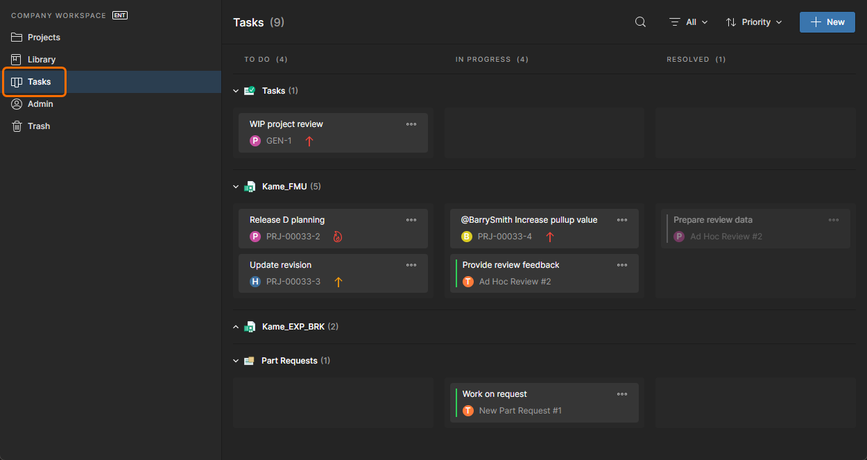
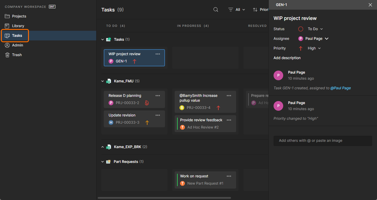
Although presented through a relatively simple interface, the Workspace Tasks dashboard offers a flexible and efficient way of both managing and tracking workflows within the actual design environment rather than via an external system. This page is a global view of all Tasks that are currently active in the Workspace, while the project-specific Tasks view available from the navigation tree when viewing a project represents only those Tasks associated with that project.
Trash
This page presents all items that have been 'soft deleted' – items that have been deleted, but not yet permanently so. The Trash is essentially a recycle bin into which any item within your Enterprise Server can be moved (through a soft delete action). It is isolated from the rest of the server and so any item in the Trash is not available for use and cannot be found through searching, or through pages in the browser interface, or from within Altium Designer.

When you delete an item in the Enterprise Server through a soft delete action, it will be moved to the Trash. The Trash page provides the interface to this isolated area of the server.
You will only see items that you yourself have soft deleted. An administrator will see all soft deleted items in the Trash. Each item is presented in terms of the following information:
- Its content type icon
- Its name
- Its description
- Its revision
- By whom it was deleted
- The date and time at which it was deleted (sent to the Trash).
Select an item in the Trash, then use the controls at the top-right of the list to permanently delete that item, or to restore it, respectively. Corresponding commands are also available from the ![]() menu (at the far right of the selected item).
menu (at the far right of the selected item).
.")
Select an item, then decide whether to fully restore it for use again or to permanently delete it (a 'hard delete' if you will).
Alternatively, to empty the entire Trash in a single, batch action, click the ![]() button at the top-left of the page. A confirmation window will appear alerting you to the fact that this action will delete all items permanently and that they cannot be restored thereafter. To proceed, click the
button at the top-left of the page. A confirmation window will appear alerting you to the fact that this action will delete all items permanently and that they cannot be restored thereafter. To proceed, click the ![]() button.
button.
Admin-Only Interface Elements
The following sections summarize the elements of the Enterprise Server's browser interface that can only be accessed by server Administrators – those who are part of the Administrators group. Access to these elements is through the dedicated Admin area of the left-hand navigation tree.
Settings
This page provides a collection of sub-pages for the configuration of options relating to various features and services provided by, and through, an Enterprise Server installation.

The Settings area – part of the admin-only pages within the Enterprise Server's browser interface.
The left-hand side of the page provides a navigation tree with which to quickly access various sub-pages of settings. The available pages are described below.
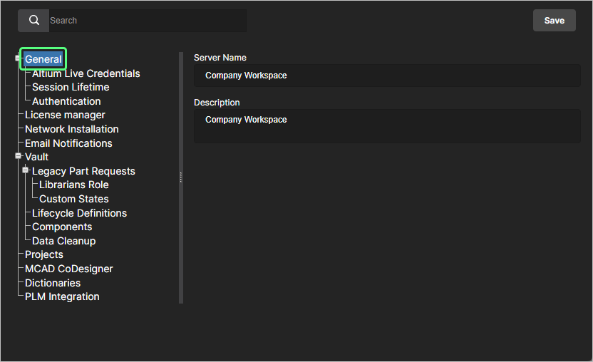
General
Use this page to change the Name and Description for the Enterprise Server.
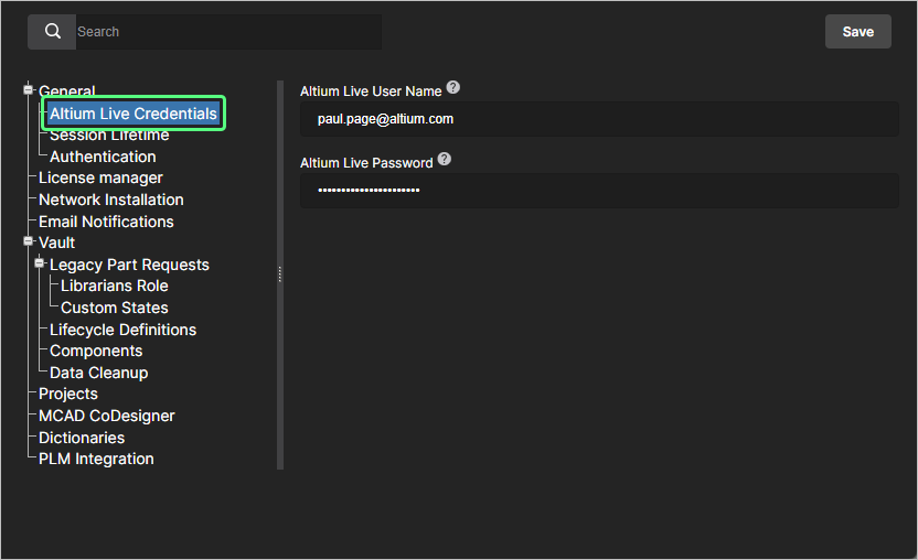
-
Altium Live Credentials – when using the Network Installation Service (NIS), use this page to enter the credentials used to log into the Altium Cloud (AltiumLive) where the installers are to be sourced from. When using the Private License Service (PLS) through the Enterprise Server, these credentials allow the PLS to communicate directly with your Altium account for the initial acquisition of your company licenses. Credentials must also be entered in order to access and obtain initial licensing for the server itself, from the Altium Cloud.
If Altium Account credentials are provided, these credentials will also be used to access the data from the Altium Parts Provider. If your Altium Account is granted access to IHS Markit part data, enter your credentials to leverage this data when accessing Part Choices in Altium Designer.
-
Session Lifetime – use this page to enter a value for the IDS Session Lifetime (in hours). This is how long an Enterprise Server user has to remain connected, in a single session, when using a seat of the applicable Client Access License (Altium Enterprise Server CAL). By default the session lifetime is 24 hours.
You can also enable the Automatic logout from connected server for inactive clients (hours) option to allow the automatic disconnect of the Altium Designer instance from the Enterprise Server Workspace when the client machine is in an inactive, or idle state, i.e., when there is no mouse or keyboard activity on the client machine and no long-term Altium Designer process such as project release is currently in progress. The value in the corresponding field specifies the time period between sending verification requests from Altium Designer (if there was no activity in the previous period, Altium Designer will be disconnected). Enter a value from
1to24hours. Note that the automatic disconnect due to inactivity functionality is available in Altium Designer 25.1 or a later version.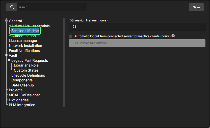
-
Authentication – this page provides settings relating to establishing, testing, enabling and disabling the SSO capability for Enterprise Server users. When set up for the users, SSO offers the convenience of signing in to the server using the same set of credentials that apply to your company-wide systems.
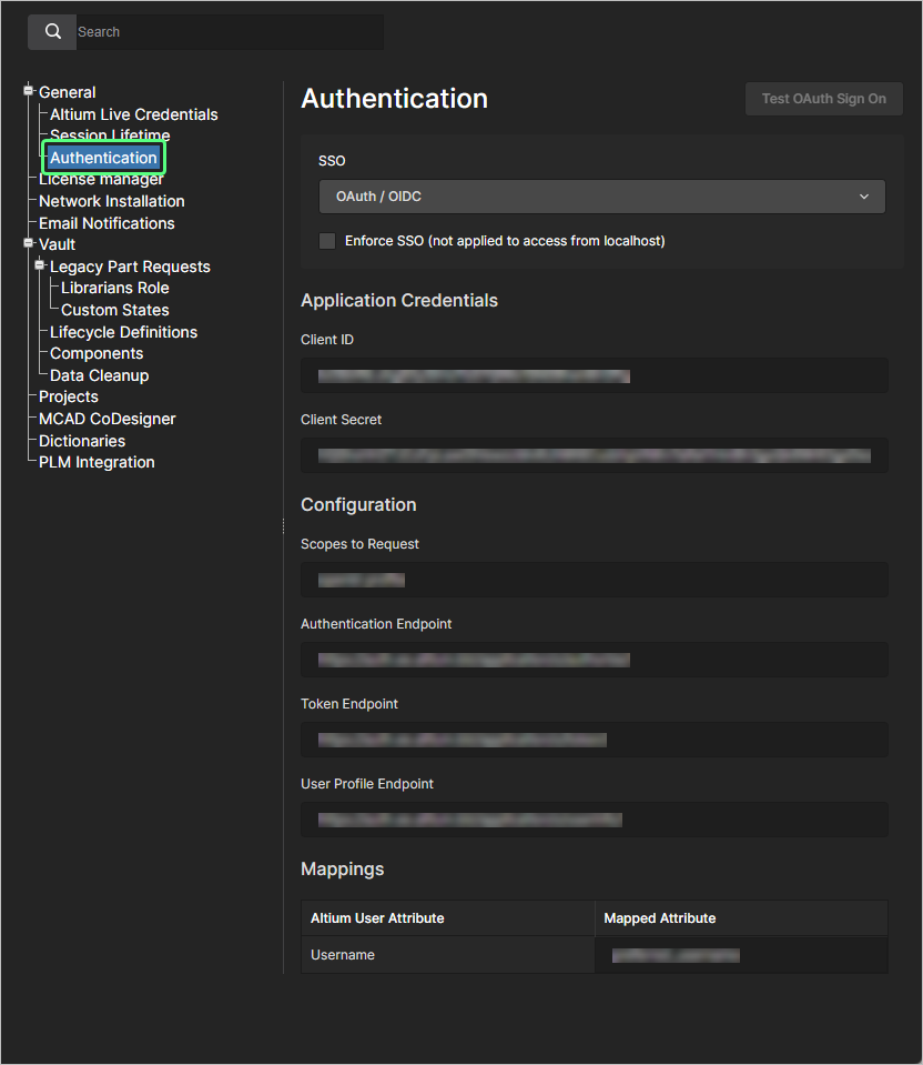
For more information, see Configuring Single Sign-on Authentication.
License Manager
This page provides settings relating to using the Private License Service and the selection of its mode. A pre-set suitable default value is used for the Altium Cloud portal URL (http://portal2.altium.com/?cls=soap).
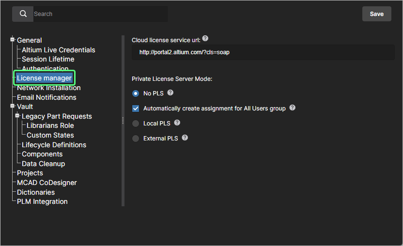
For more information, see Private License Service.
Network Installation
When using the Network Installation Service (NIS), use this page to define the update checking interval. This is the frequency (in minutes) that the Automatic Updates feature will check for available new versions of the applicable software in the Altium Cloud Repository.
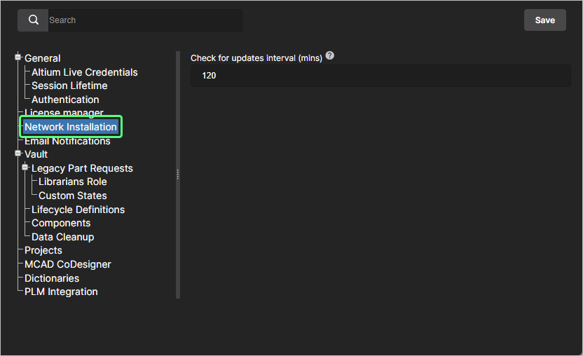
For more information, see Network Installation Service.
Email Notifications
This page provides settings to enable and configure the Enterprise Server's email notifications feature. This facility flags a variety of events to key stakeholders relating to Component Items, Projects, Approval Requests, Tasks, and Part Requests.
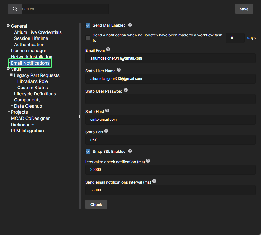
For more information, see Configuring Email Notifications.
Vault
The Vault section heading groups together settings related to specific functionality within the Workspace itself.
-
Legacy Part Requests – provides an option by which to enable use of the legacy Part Requests functionality, in addition to use of the Workflow-based Part Request functionality. Once enabled, the Legacy Part Requests page will be presented in the left-hand tree of the interface. Use the following sub-pages related to this legacy feature:
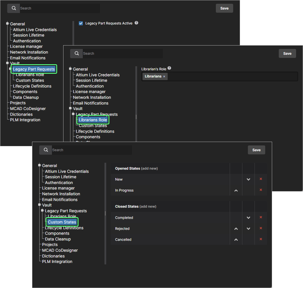
For more information, see Part Requests.
-
Librarians Group – use this page to specify which group (or groups) should be used to fulfill the group of Librarians for your organization. In essence, you are simply configuring a group of users of your Enterprise Server who can be assigned to a part request. If you installed your Enterprise Server with sample data, then the sample group Librarians will already be prefilled into the Librarian's Group field – remove if required.
-
Custom States – use this page to customize opened and closed states for the legacy Part Requests feature.
-
-
Lifecycle Definitions – use this page to define and manage your Enterprise Server's lifecycle definitions, complementing the ability to do this through Altium Designer. Providing better visibility of the states and transitions involved each lifecycle is built in a graphical way that shows the flows involved.
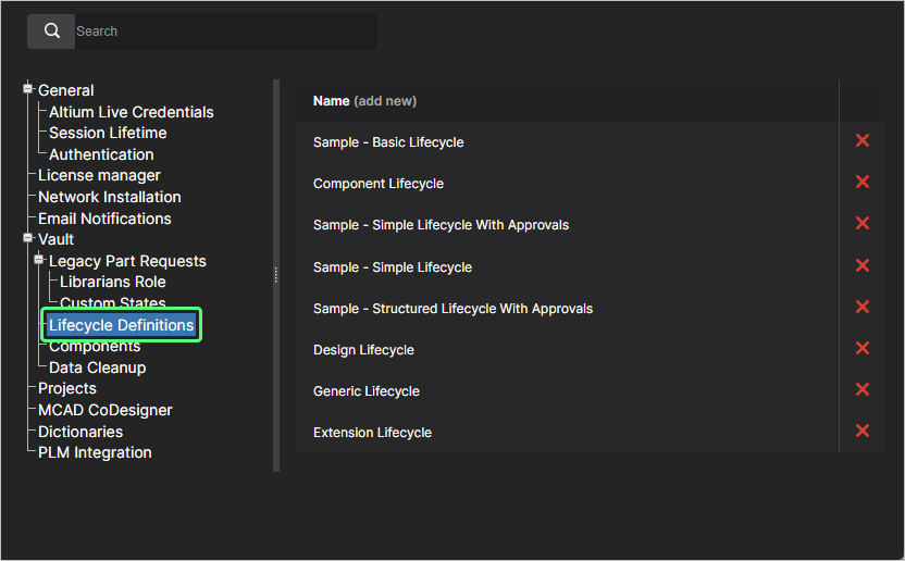
For more information, see Browser-based Lifecycle Management.
-
Components – use this page to define default target folders (within the Enterprise Server's folder structure) in which new models should be created, when creating a new Component Item. To change a default folder, click the
 button. The Explorer window will appear with which to choose the desired new default target release folder for that model type. Once chosen, click OK to close the window and return to the Components page, with the applicable field updated with the new folder path.
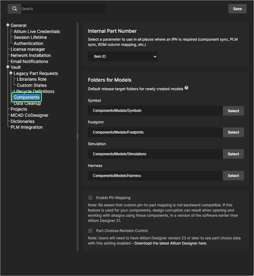
This page also includes options for enabling additional features that will become available when editing Workspace-based components in Altium Designer:
-
Check the Enable Pin Mapping option to enable custom pin-mapping. The advanced pin mapping feature, available through the Component Editor in its Single Component Editing mode in Altium Designer, allows component symbol pins to be mapped to any component footprint pad, or any number of footprint pads. This option is included because custom pin mapping is not supported by Altium Designer versions prior to 21, and is not backward compatible. If this feature is used for your components, the mapping will not be interpreted correctly when performing an ECO in a software version earlier than Altium Designer 21.
-
When the Part Choices Revision Control option is checked, Altium Designer's Component Editor (in its Single Component Editing mode) will open when editing Workspace-based component's Part Choices List, instead of the Edit Part Choices dialog. This allows a new component revision to be created in response to a changed Part Choices List, providing more formal (and traceable) control of manufacturer Part Choices data – see Part Choice Revision Control for more information.
-
-
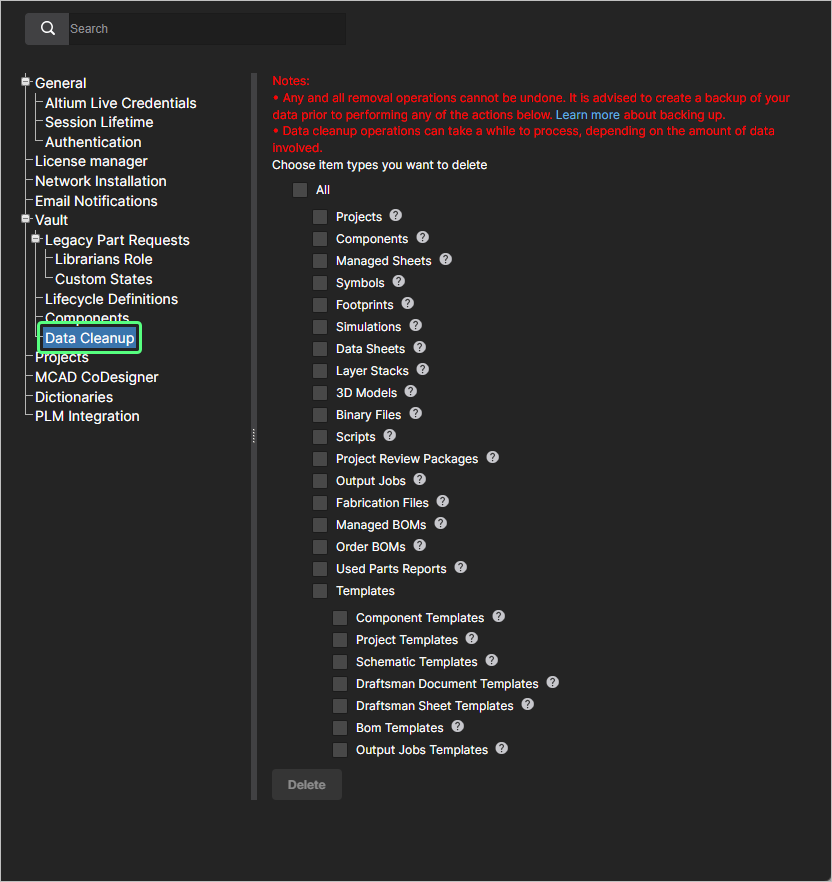
Data Cleanup – use this page to quickly delete data items from your Enterprise Server. This is particularly useful after having experimented with creating and releasing content into your Enterprise Server, for example, when trying out the migration of local file-based libraries and now you want to 'flush' such experimental data. This functionality works on any and all Item types in your Enterprise Server.
Use the available checkboxes to determine whether to delete all data items (All) or specific item types. With your cleanup strategy configured, click the
 button. A window will appear asking for confirmation, and alerting you to the fact that this action cannot be undone. To verify and proceed, enter the text Delete my data permanently into the field and then click Yes.
Projectѕ
Use this page to specify the default path (within the Workspace folder structure), and optionally the share permissions, for newly created projects. Projects will be created in the specified Default path for new projects folder entry unless a folder is already open (where it will be created), or a different path has been specified in the Create Project window’s Parent Folder field under the Advanced section – see Creating a New Project for more information.
Users who create or upload projects will require access to this default folder (initially Projects), which is determined by its sharing permissions as specified in the Workspace Explorer page – see Sharing Folders and Items for more information. Note that if a user does not have access to the default project folder (and other folder is not open), the system will create a Personal Folder structure that incorporates a My Projects folder for project storage – see Project Creation Without Folder Write Access for more information.
Permissions for a new project always include administrators and the user who created the project (its ‘owner’). Also included is the permission set inherited from its parent folder, unless this is overridden by the Default permissions for new projects option. When enabled, this option’s settings will impose a specified set of access permissions on newly created projects rather than those inherited from its parent folder – see Default Project Creation Permissions for related information.
 An administrator can define the default settings for newly created projects. Initially, the path is set to Projects and the Default permissions option is disabled.
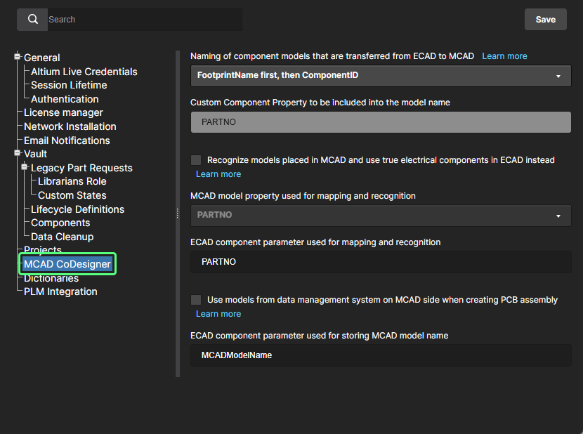
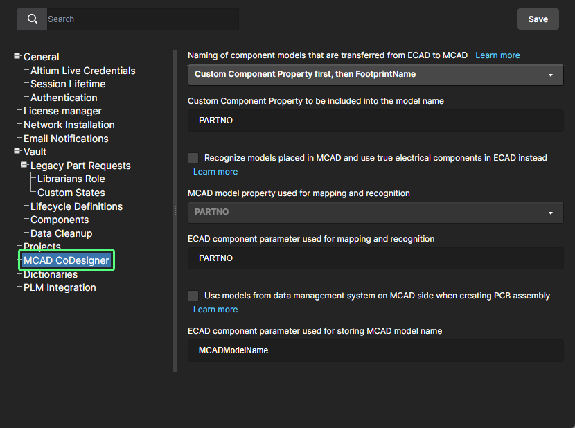
MCAD CoDesigner
This page provides controls to enable component recognition between the ECAD and MCAD domains, when using the ECAD-MCAD CoDesign feature. This facilitates the use of native components when a design is pushed and pulled between the two domains. The following options are available:
-
Naming of component models that are transferred from ECAD to MCAD – use the options to specify how components are named when initially pushed to the MCAD domain. The naming drop-down menu provides combinations of ECAD Footprint Name, Component ID or a Custom Property for the transferred model name on the MCAD side, where the Custom Component Property, if that option is selected, is entered in the field below.
-
Recognize models placed in MCAD and use true electrical components in ECAD instead – enable this option to the support use of native components when the board is being Pushed from MCAD and Pulled into ECAD. The MCAD 3D model is linked to the equivalent Altium Designer component, so when the board is pulled into Altium Designer the MCAD 3D model can be replaced by an instance of the fully-defined Altium Designer component footprint, complete with a 3D model. Use the two sub-fields to determine the MCAD model property and the ECAD component parameter, which are used to identify components in the two design domains. By default, these fields are populated with the entry PARTNO. The MCAD model property can be your own custom property, or choose MCAD model name from the drop-down. The ECAD component parameter can also be your own custom parameter. These fields are required if the parent option is enabled. If one or both are left blank, the
 button will be disabled.
-
Use models from data management system on MCAD side when creating PCB assembly – enable this option to support the use of native components when the board is being Pushed from ECAD and Pulled into MCAD. The MCAD software gets the model of the component from the MCAD's data management system (by the model’s name) and then places that component on the MCAD PCB assembly, instead of the model that came from ECAD. Use the sub-field to determine the ECAD component parameter that will be used to store the MCAD model name. By default, this field is populated with the entry
MCADModelName. This field is required if the parent option is enabled. If left blank, the button will be disabled.
Dictionaries
Use this page to create custom parameters with several defined values (Dictionaries) that can be applied to Component Templates through Altium Designer. Multiple parameter Dictionaries can be added, with each entry containing a listed choice of corresponding parameter values. When used, this approach provides a more formalized control over the application of parameter data, where standardized parameters and their value choices are centrally managed in one accessible location.
 Create predefined lists of parameter values using the Dictionaries option under Admin - Settings.
To add a Dictionary entry, click the ![]() button and then enter an appropriate parameter type name in the following Create Dictionary window. Add parameter values using the
button and then enter an appropriate parameter type name in the following Create Dictionary window. Add parameter values using the ![]() option associated with the Dictionary entry's name – press Enter to confirm the entered value.
option associated with the Dictionary entry's name – press Enter to confirm the entered value.
 Multiple Dictionaries can be created with multiple parameter values.
In Altium Designer, Dictionaries created in the Altium 365 Workspace become available as Parameter data Types when creating or editing a Component Template. Where that Template is used for creating a new component – or when editing a component based on that Template – the Dictionary-defined parameter entries will offer only those value choices defined in the Workspace Dictionary. Note that Dictionary-based parameters are indicated by their associated icon.
For more information, see Support for Dictionary-defined Component Parameter Data Types in Altium Designer's Component Editor.
PLM Integration
This page provides the Enable new PLM Configuration page option to revert (when unchecked) the advanced PLM configuration GUI and process to the previous system based on uploading a configuration file.
Also, when a Teamcenter PLM Addon license is added to the Enterprise Server, the page includes the Teamcenter EDA region that contains Altium Library Name and Altium Application Name options. Their values must match those for libraryName and applicationName used in the *_edadef.xml configuration file. When left empty, the default value of altiumLibrary is used.

For more information, see PLM Integration.
Users
Related page: Managing Users & Groups – Users
This page is used to create and manage a list of Workspace members; people who are to have access to the Enterprise Server and/or the associated technologies installed with it.
Groups
Related page: Managing Users & Groups – Groups
This page is used to create and manage a list of groups; groups allow you to further organize your users according to, for example, the particular section of the organization in which they are involved, or the design team they are in. Groups also make the sharing of Enterprise Server content, and the configuration of other served technologies, more streamlined.
Sessions
Related page: Managing Users & Groups – Sessions
This page is used to quickly assess which of your users are currently signed into the Enterprise Server. Provision is made for an administrator to terminate a user's access to the server by effectively 'killing' their active session, thereby freeing connections to the server for use by others.
LDAP Sync
Related page: Managing Users & Groups – LDAP Sync
This page is used to configure and run an LDAP Sync task. This allows an administrator of your Enterprise Server to leverage the network domain’s existing username and password credentials, so that user credentials do not have to be created manually one at a time on the Users page. When set up correctly the Users page will automatically populate with user credentials, enabling any user listed to connect to the server using their regular corporate network username and password.
Configurations
Related page: Environment Configuration Management
This page provides the interface to the Team Configuration Center (delivered through the Enterprise Server installation as the Team Configuration Service). The group of the Team Configuration Center (sometimes referred to as TC2) is simplicity itself – to give the organization centralized control over the environment its designers operate in. It achieves this through the definition and management of Environment Configurations. These are used to constrain each designer's Altium Designer working environment to only use company-ratified design elements, including schematic templates, output job configuration files, and workspace preferences. In other words it facilitates Centralized Environment Configuration Management.
Any number of environment configurations may be defined through the Center's dedicated browser interface. The data used and enforced by each configuration – referred to as Configuration Data Items – are sourced from the Enterprise Server. And by associating each environment configuration with a specific user group, and in turn assigning users to those groups, the correct working environment is loaded into Altium Designer as soon as the user signs in to the Enterprise Server. Using this group-based approach ensures that a designer always gets the setup they are entitled to, no matter whether they have their own PC, or are sharing a single PC with fellow designers.
Part Providers
Related page: Part Source Configuration
This page enables you to define a list of Part Sources – facilitating centralized supply chain management, with designers across the entire organization using the same approved list of Suppliers with which to source supply chain intelligence for parts used in their designs.
PLM Integration
Related page: PLM Integration
This page provides the interface to the PLM Sync Service. It is from here that you define the connection to a PLM instance and enable/configure synchronization of your PLM components with those in the Enterprise Server.
The Enterprise Server facilitates the uni- or bi-directional synchronization of component data with your enterprise systems. Interaction between the Enterprise Server and the enterprise system – typically a PLM system – is configured and managed through the server's PLM Integration page. This provides an automated interface for easily configuring the interconnection, mapping parameter data, and specifying the direction of data synchronization. Component data synchronization between the Enterprise Server and the target enterprise system uses a built-in synchronization process which may be manually triggered or set as a timed repeating event.
A dedicated Project Creations workflow is available that supports the automatic creation of part numbers in your PLM instance, and then propagation of these to the Workspace as project parameters. You also can publish a design to your PLM instance as part of running the Project Releaser in Altium Designer.
Processes
Related pages: Creating & Managing Processes, Defining a Process Workflow
This page provides the interface to create and manage Workflows that guide a company's designers through typical, everyday design processes such as:
-
Requesting new library parts
-
Performing project-related activities, such as design reviews or publishing to a PLM
-
Creation of new projects.
A powerful Process Workflow Editor provides the flexibility for you to build processes with workflows that can be as simple, or as complex as needed, and in-line with your company's requirements. Build the workflow graphically and then define the required aspects of each element in that flow. For user tasks, a User Form Editor is used to fashion the required form that will be presented to the user, to take their input when they are given a task at the relevant point along the workflow. Once a process has been defined as required, click the ![]() button to have it added to the list of available processes for that particular area of the software.
button to have it added to the list of available processes for that particular area of the software.
Licenses
Related pages: Licensing, Private License Service
This page provides the interface to obtain and manage licenses – both for the licensing of the Enterprise Server itself and also for serving to client machines over the local network, through the appropriately configured Private License Service (PLS).
Status
This page provides status-related information for the Enterprise Server and quick access to log files. It is presented over three regions:
-
Installed Services – providing version information for the current Enterprise Server installation.
-
Path to database and files – providing information about the installation paths for the database and data, including the type of database being used by the Enterprise Server.
-
Logs – providing information about the installation path to log files. For each distinct service click on the associated
 icon to download a zip containing the relevant set of log files.

The Status page provides installation details, as well as log files for the various services.
Health
Related page: Health Monitor
This page provides a browser-based Health Monitor. The page delivers a visual summary of the state of the host machine and the Enterprise Server storage system. The page is a browser-based companion to the server's Health Monitor tool that is available as a standalone application on the server host machine (sourced from the installation's Tools folder), but offers the advantage of being remotely accessible by administrators over the network.
Installations
Related page: Network Installation Service
This page provides the interface to the Network Installation Service, through which you can perform installations or updates to Altium products over your local network, and enables centralized control of software availability, configuration and its capabilities. Using NIS you acquire software product files from Altium and then assemble these into a configurable software deployment package. The locally stored package can then be deployed to networked workstations as a software installer executable (*.msi), or as a direct installation using Microsoft’s Active Directory Group Policy.
Explorer
Related page: Managing Content Structure & Access
This page gives you access to the structure of the Enterprise Server and is similar in presentation and layout to that of the Explorer panel in Altium Designer. From here, you will be able to browse the folders and Items within the Enterprise Server. And although you can't create or edit Items from within the browser interface (you can remove them), you are able to create and edit folders, and so build the structure of the server without having to be signed in to that server through Altium Designer.
You can also define sharing from this interface – controlling who is able to see what content in the Enterprise Server and, at the folder level, whether other users can simply view a folder and its content, or also edit it (effectively releasing/committing/uploading design data into it). A single Enterprise Server installation can be partitioned into various effective 'zones' of content, but with controlled permissions the content can be made selectively visible, or hidden, as required – giving the right people, the right access, to the right data.
Content can also be downloaded from the Enterprise Server directly from this interface. Enterprise Server Administrators will be able to see and manage all Workspace content. For a shared user of the Enterprise Server (non-admin), only those folders that have been shared – that is, the user has permissions to access – will be accessible when the user signs in to the Workspace.
 AI で翻訳