
Device Sheets
Parent page: Design Reuse
There is a strong incentive to re-use sections of circuitry from existing designs; the design is proven so the engineering is complete, it saves time, it can help reduce component inventory, and it frees up your design team to focus on the development of new concepts and products.
Designers are clever people, they already reuse existing designs all the time. It might be a proven circuit that they re-capture, or perhaps they copy and paste from an existing design, or perhaps they link an existing schematic sheet into a new design.
Device Sheets simplify the design process by providing modularized and consistent building blocks which can be re-used between projects. Device Sheet Symbols are placed and referenced similarly to components. They are connected to and function in the same way as a sheet symbol that is referencing a standard schematic document, but are not explicitly added to a project.
Device Sheets
Device Sheets are building blocks developed with the intent of being re-used in different designs. They usually contain predefined circuits that are useful in multiple projects, for example a power supply.
 One Device Sheet can be used across multiple projects.
A Device Sheet is created and stored as a normal schematic document, in a declared Device Sheet Folder. Rather than being added as a document, they are placed and referenced in a project in a similar way as a component. When the project is compiled, Device Sheets are included in the project hierarchy and can be distinguished from standard schematic documents by a different document icon in the Projects Panel.
By default, Device Sheets are usually configured to be read-only. This gives all designers in the team confidence that they are complete and ready-for-use, and also insures that no one in the design team can inadvertantly modify them. Because they are configured to be read-only, the component designators cannot be changed, nor can the schematic sheet number.
The fundamental difference between a device sheet and a regular schematic sheet is that the software has additional features to handle component annotation and the schematic sheet numbering when the project includes Device Sheets.
Enabling Device Sheet Support
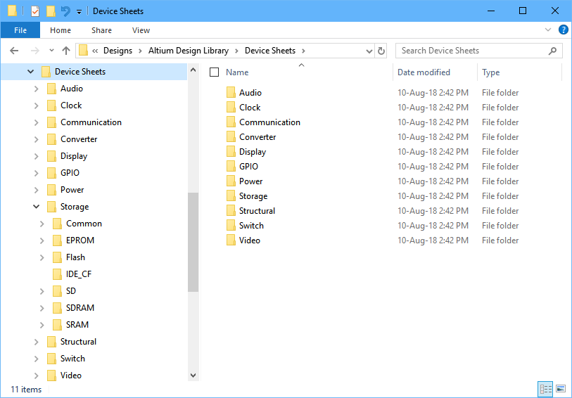
- Using Windows File Explorer, create a folder in a suitable location to hold your Device Sheets. If required, you can create a parent folder called
Device Sheets, with sub-folders to suit your company's requirements, such as,Data Conversion,Powerand so on.
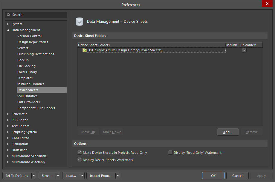
- The Device Sheet parent folder is declared in the Data Management - Device Sheets page of the Preferences dialog, as shown below. Enable the Include Sub-folders option if required.
Creating a Device Sheet
A Device Sheet can be any normal schematic sheet, including a schematic that contains Sheet Symbols that reference other schematic sheets. It is the fact that they are placed as a Device Sheet from the Device Sheet folder that flags to the software that this schematic sheet is a Device Sheet, that the Device Sheet control options defined in the Preferences dialog must be applied, and the special annotation and sheet numbering commands obeyed.
By default, Device Sheets are usually configured to be read-only. The challenge of working with Device Sheets is not protecting that chunk of design from modification, it is dealing with the design finalization tasks that are carried out when the design is complete, namely schematic sheet numbering and component annotation.
There are some preparatory steps that should be taken before a schematic is copied or moved into the Device Sheet storage folder:
- Think of the Device Sheet a completed piece of work, make sure it has the correct template applied, with the required company annotations and special strings defined.
- Using a systematic naming scheme for Device Sheets can help order the Device Sheets in the Select Device Sheet dialog.
- Annotate the Device Sheet schematic (Tools » Annotation » Annotate Schematics) before putting it into the Device Sheets folder. Some designers use a simple, flat component numbering scheme, others include a suffix to reflect the function of that circuitry. When the design is complete, all of the sheets and components can be renumbered across the project.
Using a Device Sheet in your Project
A Device Sheet is used in a project by placing the Sheet Symbol that represents it. To do this:
- Run the command Place » Device Sheet Symbol.
- The Select Device Sheet dialog will open. The tree on the left will show the folder structure below the folder chosen in the Data Management - Device Sheets page of the Preferences dialog. Any schematic sheets detected in the selected folder will be listed on the right side of the dialog, as shown below.
 Select the correct Device Sheet folder on the left, then the required Device Sheet on the right.
- Select the required Device Sheet and click OK. You will be returned to the schematic editor, with the Sheet Symbol for that Device Sheet floating on the cursor, as shown below.
 A Device Sheet Symbol during placement, hover to show it placed.
- Single click to place the Sheet Symbol (hover the cursor over the image above to show the placed Sheet Symbol). Note that the Device Sheet Symbol is different from a Sheet Symbol that references a regular schematic sheet, having rounded corners and a recycled symbol. You are free to resize the placed symbol, and relocate the Sheet Entries.
- Compile the project to display the Device Sheet in the project structure in the Projects panel. Note that a different document icon is used to represent a Device Sheet, when compared to a regular schematic sheet.
 Once the project has been compiled the Device Sheet will appear in the project hierarchy, using a special Device Sheet icon.
► Learn more about Creating Connectivity.
Device Sheet Properties
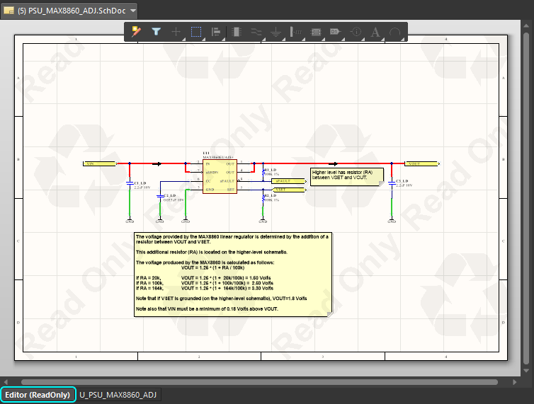 A Read-Only Device Sheet. Note the Editor Tab at the bottom of the design window has the suffix (ReadOnly) to indicate that you are viewing a Device Sheet
which cannot be edited. There is also an option to display a Read Only watermark and a Device Sheet (recycle) watermark.
Once you have placed a Device Sheet Symbol and compiled your project, open the Device Sheet itself to view its graphical properties. The default setting in the software is for Device Sheets to be read-only, as configured in the Options section of the Data Management - Device Sheets page of the Preferences dialog. Note that the Read-Only option is independent of the display of the Read Only Watermark across the sheet, check the Editor tab at the bottom of the editing window to see if a sheet is ReadOnly (as shown above).
Editing a Device Sheet
You can edit Device Sheets in one of two ways; either directly in your project, or from the source schematic documents in the Device Sheet folders.
Edit Device Sheets Directly in your Project
To edit Device Sheets directly in your project:
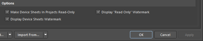
- Click the Gear icon at the top right to open the Preferences dialog.
- Navigate to the Data Management - Device Sheets page in the Document Management section of the dialog.
- Disable the Make Device Sheets in Projects Read-Only checkbox and click OK.
Edit a Device Sheet from the Device Sheet Folder
To edit Device Sheets from your Device Sheet folders:
- Close all open projects that reference the Device Sheet. You will not be able to open a Device Sheet as a source schematic if there is a project currently open that references that Device Sheet.
- Use the File » Open command to open the Device Sheet from its source in the Device Sheet folder. The sheet will present as a standard schematic, without any watermarks.
- Make the modifications as required, save the changes and close the Device Sheet.
Hierarchical Design with Device Sheets
A Device Sheet may contain Device Sheet Symbols, although a Device Sheet cannot be the top sheet in a project due to hierarchical implications. There are no limitations to the depth of the hierarchical structure when using Device Sheets.
To prepare hierarchical Device Sheets:
- Prepare and save all of the relevant child schematic documents as Device Sheets, in the Device Sheet folder.
- Place the Device Sheet Symbol(s) in the parent schematic, and save this in the Device Sheet folder.
 This schematic is a Device Sheet and it also has a Device Sheet Symbol placed on it, referencing a child Device Sheet.
Refactoring your Design with Device Sheets
Main article: Design Refactoring
The process of design is often unstructured and organic, the designer could be formulating ideas for multiple parts of the design at the same time, capturing sections as their ideas evolve. That means that what started out as a well organized, neatly laid out set of schematics can become crowded and poorly organized. While you can Cut, Copy and Paste to reorganize the schematic design, this is not always the best approach.
Why not cut and copy? Because as each component is placed it is assigned a unique identifier, and this identifier is automatically reset whenever a component is Cut/Copied and Pasted. This UID management is done to ensure that there is only one instance of each UID used in the design, as it is the key field that links the schematic component to the PCB component. The Cut/Copy/Paste approach is fine if the design has not been transferred to the PCB editor, but if it has, then it is better to use the refactor tools.
Moving a Sub-circuit to Another Sheet
The easiest way to move a section of circuitry from one sheet to another is to select it, then run the Edit » Refactor » Move Selected Sub-circuit to Different Sheet command (also available via the right-click menu when there is a selection). The Choose Destination Document dialog will open, after you select the target sheet and click OK that sheet will appear, with the sub-circuit floating on the cursor, ready to position.

A selected section of circuitry can easily be moved to a different sheet in the project using the Move Selected Subcircuit to Different Sheet command.
The refactoring commands support:
- Converting an existing schematic into a Device Sheet.
- Converting a Device Sheet into a regular schematic sheet.
- Moving a section of circuitry to another sheet.
- Converting a part to a Sheet Symbol.
► Learn more about Design Refactoring.
Annotating the Components and the Sheets
To guarantee the integrity of the circuitry used in a Device Sheet, that sheet should not be edited during normal design use. That means the sheet number and designator assignments should not be modified on the sheet, so just how do you number all the sheets in the project and annotate all of the components?
These tasks are managed by two commands; sheets are numbered using the Annotate Compiled Sheets command, and components are annotated using the Board Level Annotation command. Sheet number and designator assignments are stored in a separate file, <ProjectName>*.annotation.
Annotating Compiled Device Sheets
Main article: Numbering the Sheets
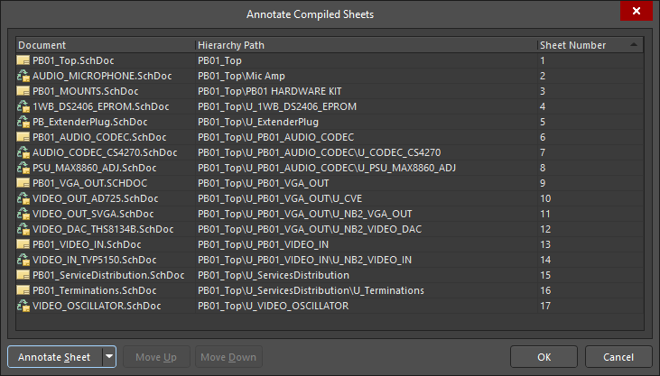
Complimenting the Board Level Annotation feature, the Tools » Annotation » Annotate Compiled Sheets command is used to uniquely number Device Sheets, without modifying the source schematics. As with component annotations, the sheet numbers are stored in the <ProjectName>*.annotation file.
Notes about sheet numbering:
- Sheets can be numbered according to the order they appear in the Projects panel, this order can be changed in the Projects panel using drag and drop. Save the project after changing the order, so that the project file reflects the latest order when an annotation dialog is used. Note that drag and drop order changing is not supported for Device Sheets.
- Number the non-Device Sheets using the Tools » Annotation » Number Schematic Sheets. Press F1 over the dialog to learn more about the options and controls.
- Then number all sheets in the the compiled project, including Device Sheets, using the Tools » Annotation » Annotate Compiled Sheets.
- Numbering dialogs support entering values directly, this approach can sometimes be more efficient.
- Many of the dialogs have dual purpose buttons, such as the Annotate Sheet button (shown above):
- Click the down arrow on the button to reveal the numbering options, configure these as required,
- Then click the main part of the button to number in accordance with the options just selected.
► Learn more about Annotating Compiled Sheets.
Component Annotation
Main article: Annotating the Components
To allow the component designators to be uniquely assigned across the entire project, the software includes a feature called Board Level Annotation. This command does not edit the source schematic sheets, rather it stores mapping information, mapping each logical schematic designator to a physical PCB designator, as they will appear on the PCB. These designator mappings are stored in a project file called <ProjectName>*.annotation. There is a broad range of annotation options available in the Board Level Annotate dialog.
 Board Level Annotation allows the completed design to be re-annotated, assigning a unique physical designator to each component.
Notes about working with Board Level Annotation, referring to the image above:
- All schematic components must be assigned a designator before running the Board Level Annotate command, using the Tools » Annotation » Annotate Schematics command. This insures that the schematic source data, including packaged options for multi-part components, is available as input for the Board Level Annotation process. Note that components on Device Sheets should have already been annotated when the Device Sheet was opened for editing as a source file.
- Board Level Annotation is performed by running the Tools » Annotation » Board Level Annotate command.
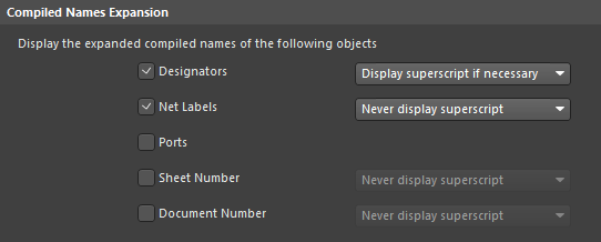
- In the image above, the schematic Editor tab is active. This tab always shows the logical designators at the standard size, with the assigned physical (PCB) designators shown in superscript. The Compiled tab of the schematic (U_CVE in this example) is the opposite, it shows the physical designators at the standard size, with the logical designators shown in superscript. This behavior is configured in the Schematic - Compiler page of the Preferences dialog, as shown below.
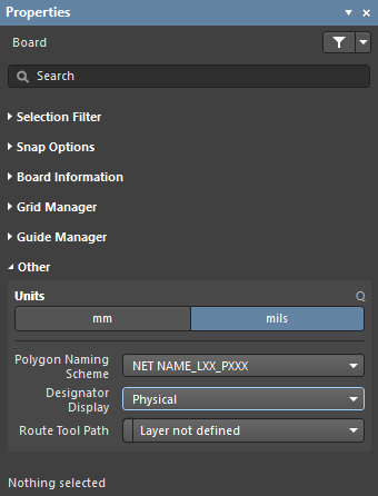
- The default behavior in the PCB editor is to display the physical designators. This can be changed in the Properties panel in Board mode, as shown below (displayed when nothing is selected in the PCB workspace).
► Learn more about Board Level Annotation.
Troubleshooting
If you open a project containing Device Sheets and the location of these Device Sheets has not been declared, you will see the following dialog with a list of the Device Sheets which cannot be found.
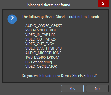
If you click Yes, the Device Sheet Folders section of the Data Management - Device Sheets page of the Preferences dialog will appear. It might be that the Include Sub-Folders option has not been enabled, otherwise add in the new path if the Device Sheets used in the project are stored in a different location.