
KB: Troubleshooting Allegro Design Import in Altium Designer
 Altium Designer
Solution Details
Typical failures during Allegro imports
Users may encounter issues when importing Allegro *.brd or *.dra files into Altium Designer. Common symptoms include timeout errors such as Cadence Allegro extracta.exe has timed out, unable to continue translation, failed imports, or the inability to convert binary Allegro files into a format that Altium Designer can process. These issues are commonly associated with missing Allegro utilities, incorrect environment variable configuration, expired Allegro licenses, or large design files. Altium Designer supports importing Allegro binary and ASCII files up to Allegro version 17.4.
Dependency on Allegro conversion utilities
Altium Designer ultimately requires Allegro ASCII (*.alg) files for import. Binary Allegro files must first be converted using extracta.exe, which is installed as part of Allegro and depends on a valid Allegro license. Because these utilities and supporting DLLs cannot be redistributed with Altium Designer, the conversion must occur on a system where Allegro is installed. Once the design has been converted to ASCII format, the resulting *.alg file can be imported into Altium Designer without requiring Allegro on that machine.
Conversion workflow overview
- Option 1 – Automatic Conversion: Use when Allegro and Altium Designer are installed and licensed on the same machine.
- Option 2 – Manual Conversion: Use when Allegro is installed on a different machine or the automatic conversion fails. Workflow differs depending on Altium version:
- AD 26.1 and Later: The
Allegro2Altium.batfile is self-contained and no additional extraction definition files are required. - Before AD 26.1: The conversion process requires additional configuration files such as
AllegroExportViews.txtandAllegroPackageExportViews.txt.
- AD 26.1 and Later: The
- If no system with Allegro installed is available, consider contacting an Altium Service Bureau that offers Allegro conversion services.
Conversion and import steps
Option 1: Automatic Conversion (Allegro and Altium Designer installed on the same machine)
- Confirm Allegro is installed (e.g.,
C:\Cadence\SPB_17.2). - Open the Start menu and select Settings.
- Navigate to System » About
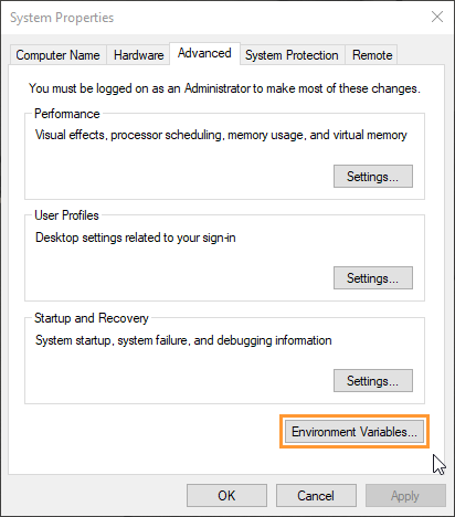
- Under Device specifications, select Advanced system settings.
- In the Systems Properties dialog, Environment Variables....
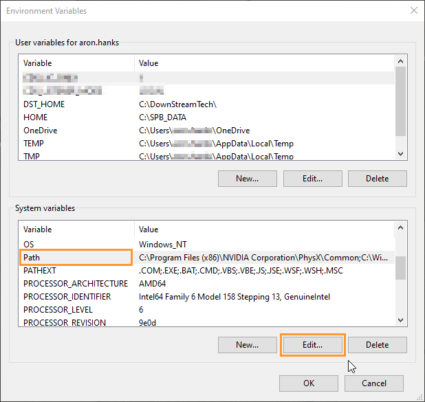
- In the Systems Variables section, select the Path variable and click Edit.
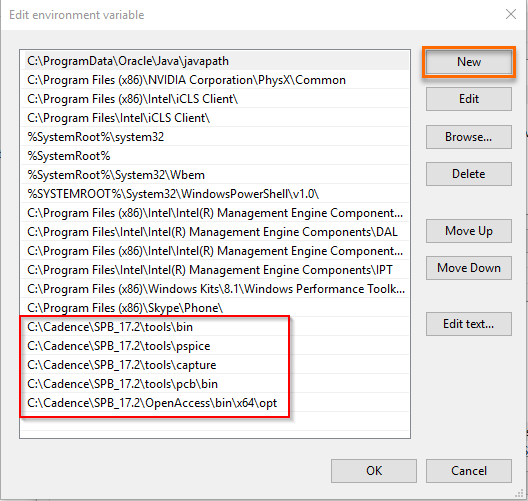
- Add the required Allegro installation paths:
C:\Cadence\SPB_17.2\tools\binC:\Cadence\SPB_17.2\tools\pspiceC:\Cadence\SPB_17.2\tools\captureC:\Cadence\SPB_17.2\tools\pcb\binC:\Cadence\SPB_17.2\OpenAccess\bin\x64\opt
- Create a system variable:
Name:CDSROOT
Value:C:\Cadence\SPB_17.2(or your installed version)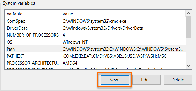
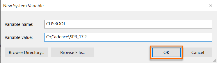
- Verify configuration in Command Prompt:
echo %CDSROOT%echo %PATH% - Restart the PC.
- In Altium Designer, go to File » Import Wizard.
- Select Allegro Design Files and add the
*.brdfile. - Proceed through the wizard and configure options.
- Carefully verify layer mapping, including stackup, plane layers, and mechanical layers.
- Finish the wizard and verify the generated
.PcbDoc.
Option 2: Manual Conversion Using Allegro2Altium.bat
- Prepare files for conversion:
- Copy the Allegro design file (
*.brdor*.dra). - Copy
Allegro2Altium.batfrom the Altium installation folder
(e.g.,C:\Program Files\Altium\AD26.8.1\System) - For versions prior to AD 26.1: also copy:
AllegroExportViews.txtAllegroPackageExportViews.txt
- Copy the Allegro design file (
- Place all files in a working folder on a machine where Allegro (with
extracta.exe) is installed. - Open Command Prompt and navigate to the working folder:
cd C:\WorkingFolder - Run the conversion:
Allegro2Altium PCBName.brd - Wait for completion. Output files include:
PCBName.brd.algextract.log
- Review
extract.logif errors occur. - Copy the generated
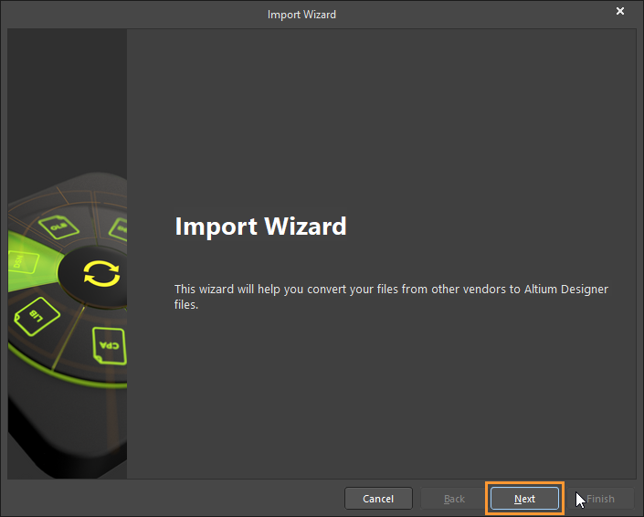
*.algfile to the machine running Altium Designer for import. - Launch Altium Designer, select File » Import Wizard, and click NEXT on the Welcome page.
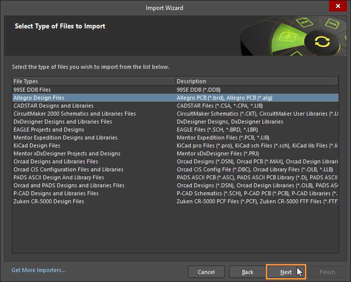
- Select Allegro Design Files in the Select Type of Files to Import dialog and click Next.
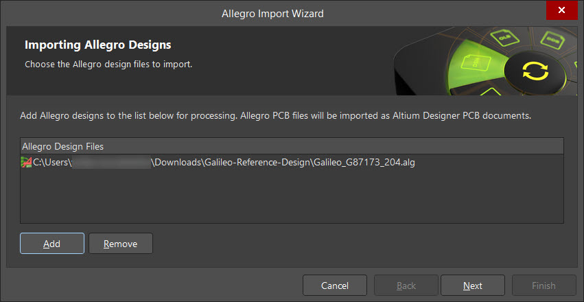
- In the Importing Allegro Designs dialog, click Add. Browse to the location of the Allegro design file (
*.alg), select the file, and click Open.
- Verify that the correct file is listed and click Next.
- If available, add the Allegro Constraint Manager
.DCFXfile by clicking Add, browsing to the file location, selecting the file, and clicking Open. Click Next to continue.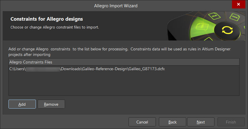
- Wait while Altium Designer analyzes the selected files. Progress is displayed in the Analyzing Files page. When the analysis is complete, the next page of the Import Wizard opens automatically.
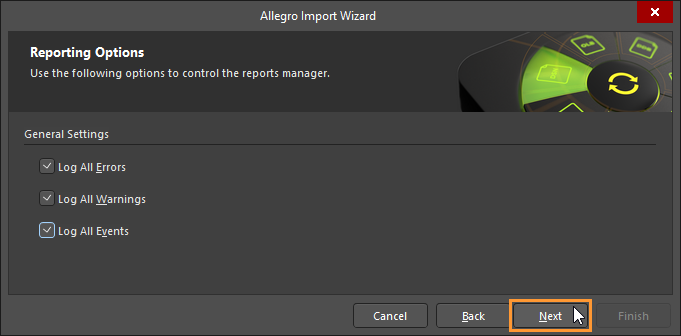
- In the Reporting Options dialog, select any desired log files and click Next.
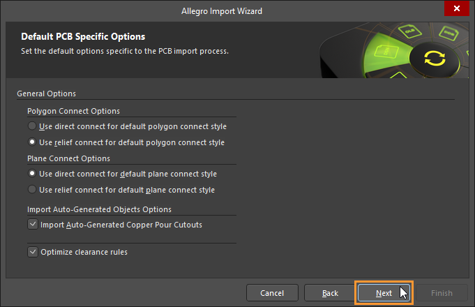
- In the Default PCB Specific Options dialog, configure the desired settings for Polygon Connections, Plane Connections, and Auto-Generated Objects, then click Next.
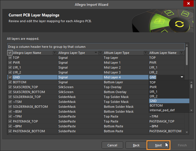
- In the Current PCB Layer Mappings dialog, review the layer mappings and make any necessary adjustments. To change a mapping, select the corresponding cell and choose the desired layer from the drop-down list. After verifying the mappings, click Next.
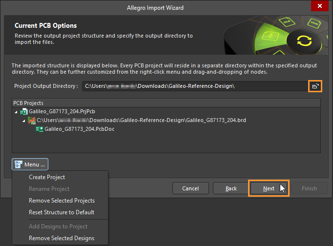
- In the Current PCB Options dialog, review the output project structure and specify the directory where the imported files will be created. Use the Browse Folder button to select the Project Output Directory. If necessary, click Menu to modify the project structure. Click Next to continue.
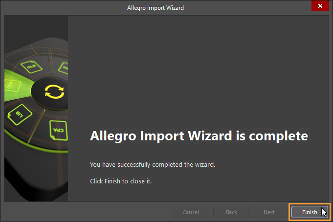
- Wait while Altium Designer generates the imported project. Progress is displayed in the import progress window. When the import is complete, click Finish to close the Allegro Import Wizard.
- After the import completes, review the translated design and verify that the Allegro design has been successfully converted into an Altium Designer
.PcbDoc.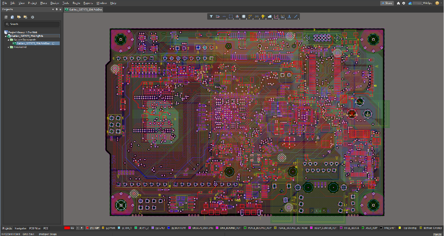
Additional Notes
- From AD 26.1 onward, the Allegro import workflow is simplified because the
Allegro2Altium.batfile is self-contained and no longer depends on external configuration files. In earlier versions, matching configuration files were required and had to align with the tool version.