
KB: Map Spice model pins to schematic symbol to avoid unexpected simulation result
Created: April 17, 2023 | Updated: March 08, 2024
While it is vital that all components in the design to have Spice models linked, it is even more critical that those linked models have pins mapped correctly with the corresponding schematic symbols, as there is no automated means for compiler to identify such pin mapping mismatch and can outputs result that is unexpected with no explict error.
Solution Details
A general procedure of finding and linking Spice model to component can be found at:https://www.altium.com/documentation/altium-designer/verifying-preparing-project-simulation#!adding_simulation_models_to_the_design
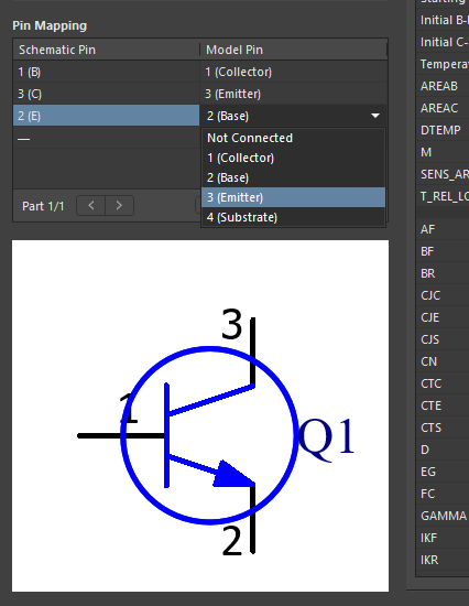
The pin mapping can be checked with the symbol selected in schdoc, in Properties panel, on General tab, under Parameters section, double-click on Simulation object to open a dialog where you can check/modify under Pin Mapping section.
For all .SUBCKT statement, it is of standard notation in Spice to list pin name in ascending order of pin index starting with 1.https://www.altium.com/documentation/altium-designer/single-component-editing#!linking_a_simulation_model:~:text=Mapping%20the%20Model%20Pins%20to%20the%20Component%20Symbol%20Pins
For .MODEL statement, it is implicitly defined in Berkeley Spice 3f5 as below:
http://bwrcs.eecs.berkeley.edu/Classes/IcBook/SPICE/UserGuide/elements_fr.html
So for example, in BJT, the pin order in model is C (1), B (2), E (3) to which schematic symbol has to be mapped manually, if different.
As a side note, pin mapping of managed component in A365 has to be done in batch editing mode:
https://www.altium.com/documentation/altium-designer/batch-component-editing#!pin-mapping
In a file-based DBLib, the simulation model related attributes can be specified as described below:
https://www.altium.com/documentation/altium-designer/creating-defining-database-library#!simulation_model_mapping
Make sure that the database is clean for each attribute, with no trailing space characters for example, as it is known to prevent the model from being linked properly.
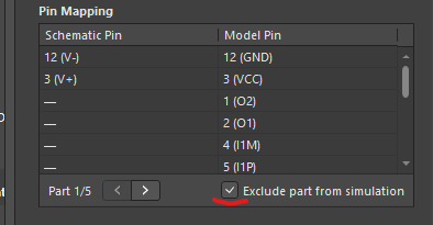
For multi-part component, by default, each part of the symbol is considered to be a separate component with the assigned Spice model by the simulation engine. In order to exclude part from simulation, the checkbox "Exclude part from simulation" in Sim Model dialog has to be ticked.
For homogeneous multi-part component (multiple copies of the same circuit model), the same mapping can be applied to all parts.
For heterogeneous component, on the other hand, all varying models needs to be encapsulated into a single file with a .SUBCKT wrapper statement.
e.g.
.SUBCKT MMDT3946 1 2 3 4 5 6
Q1 3 5 4 DI_MMDT3946_PNP
Q2 6 2 1 DI_MMDT3946_NPN
Old reference still valid in the context of model linking:
https://youtu.be/xFafdcH6J6Y?t=601