
Verifying & Preparing a Project for Simulation
The design to be simulated should be verified and adequately prepared so you can receive the proper simulation results. The relevant regions of the Simulation Dashboard panel will guide you in design verification and preparation to make sure that the design meets the requirements necessary for simulation.
Controlling the Scope of the Simulation
First of all, the scope of the simulation should be chosen using the Affect setting at the top of the Simulation Dashboard panel. The setting defines for which sheet(s) of the active project the circuit simulator makes a list of circuits:
- Document – only for the schematic sheet that is currently open.
- Project – for all sheets of the current project.

Define which schematic sheets are to be included in the simulation.
Using a Compile Mask in Simulatable Designs
Because all elements of a design covered by a Compile Mask directive are invisible to the design compiler, they will be omitted from the design. This feature can be put to great use when simulation is included as part of the design flow.
Voltage and Current sources are necessary elements when running circuit simulations, but they have no place on the completed PCB. By applying a small amount of planning to the structure of the circuit, it is usually possible to group all simulation-specific components in one section of the design – a section that can then be easily covered by a Compile Mask directive.
When the circuit is used for simulation, the Compile Mask directive is disabled to reveal the simulation-specific components. Once the circuit is verified and ready for inclusion in the design, the Compile Mask directive can be re-enabled, so that the simulation-specific components are excluded from the design. If the design should ever need to be changed again in the future, another simulation pass can be quickly executed prior to sign-off by disabling the Compile Mask directive (to reveal the simulation-specific components again).


Verifying the Design for Simulation
First of all, the schematic used in the simulation must be part of a PCB project (*.PrjPcb). If the schematic sheet is a free document, the simulation-related controls will not be available to use: the Simulate » Run Simulation command from the main menus will be inactive, as well as the Simulation Dashboard panel. A warning will be shown at the top of the panel.

Simulation is not available for a schematic that is not part of a project.
When the active schematic document is part of a PCB project, click the Start Verification button in the Verification region of the Simulation Dashboard panel to start project verification according to the chosen scope of the simulation.

Click Start Verification to verify your circuit for simulation.
A series of automated processes and checks will be invoked, which include the generation of the circuit's SPICE Netlist (*.nsx), a number of simulation-related electrical rule checks, and simulation model validity checks. The model check will detect components with missing simulation models, and models with parsing or pin mapping errors.
When there are no detected violations, a green check icon will be shown in the Verification region of the Simulation Dashboard panel.

The Verification region when there are no violations detected
If there are any detected check violations, the corresponding warnings and icons will be shown in the Verification region of the Simulation Dashboard panel. Possible violations are described below.
Violations of simulation electrical rule checks (ERC) will be listed under the Electrical Rule Check header.
Empty circuit for simulation
The schematic must include at least one component that has a simulation model. Otherwise, the simulation cannot be run, and the Empty circuit for simulation warning will be displayed. The Details link will open the Messages panel with the error message.

The Empty circuit for simulation warning
No reference node
The schematic must include a net that the simulator can use as a reference node. A net object (usually, a power port) must be connected at least to one component. Otherwise, the simulation cannot be run, and the No reference node warning will be displayed. The Details link will open the Messages panel with the error message.

The No reference node warning


Duplicate designators
Each component must have a unique designator. If duplicate designators are detected, the Duplicate Designators warning will be displayed. The Details link will open the Messages panel with the error message.

The Duplicate designators warning
Voltage source/Inductor loop found
Pins of voltage sources and inductor components must not be shorted, i.e. pins of a voltage source or an inductor must not be connected to the same net. Otherwise, the Voltage source/Inductor loop found warning will be displayed. The Details link will open the Messages panel with the error message.

The Voltage source/Inductor loop found warning
Net name errors
Net names used in the circuit must not contain SPICE-incompatible characters such as spaces and commas. Otherwise, the Net name errors warning will be displayed. The Details link will open the Messages panel with the error message.

The Net name errors warning
Global parameter errors
Values of global parameters used in the circuit must be correct. Otherwise, the Global parameter errors warning will be displayed. The Details link will open the Messages panel with the error message.

The Global parameter errors warning

Violations related to component simulation model checks will be listed under the Simulation Models header.
Components without Models
Each component must have a simulation model. If a component is missing a model, the Components without Models warning will be displayed.

The Components without Models warning
Click the Add Model control next to a specific component to access the Sim Model dialog and manually select a simulation model for that component.
Click the Assign Automatically control to add the missing models automatically. The search for available models will be sequentially performed in the following sources:
- Local – the models stored locally and located in the path defined in the Model Path field on the Simulation – General page of the Preferences dialog.
- Libraries – the installed libraries that are listed on the Installed tab of the Available File-based Libraries dialog.
- Server – simulation models from the connected Workspace.
- Octopart – simulation models available in the cloud library.
The models found will be assigned to the components, with pins automatically mapped between the component and the simulation model. The results of the auto-assignment are displayed in the Simulation Dashboard panel. When clicking the Edit Model link for an auto-assigned model, related messages (status, model candidates) will be shown in the Messages panel (in addition to opening the Sim Model dialog).
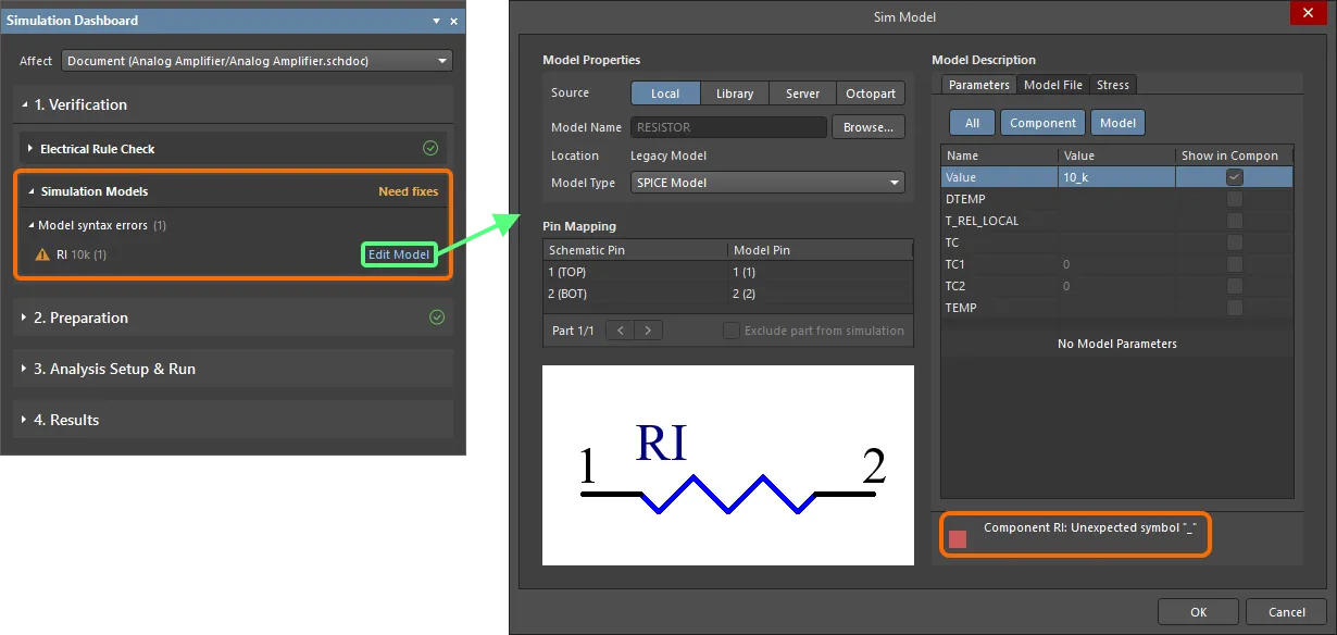
Model syntax errors
Each component must have a simulation model. If a model has syntax errors, the Model syntax errors warning will be displayed. Click the Edit Model control to access the Sim Model dialog to examine the model. The found errors will be shown at the bottom-right of the dialog.
Preparing the Design for Simulation
Adding and Configuring a Simulation Source
To simulate a circuit, the schematic design should contain at least one voltage or current source. If there is no source, the simulation can still be performed and you will be warned by the message Need to add source in the Preparation region of the Simulation Dashboard panel. A voltage or current source can be placed in schematics by clicking the Add control in the Simulation Sources region of the Simulation Dashboard panel and selecting the Voltage or Current command from the menu or by using the Place Voltage or Place Current command from the Simulate main menu or the simulation command menu in the Active Bar.

Simulation sources should be added to the circuit. That can be done right from the Simulation Dashboard panel.
Once a source has been placed, its properties can be changed in the Properties panel. Notes about configuring the properties of a source:
-
Stimulus Name is the assigned name of the signal. You can create new signals for the schematic or remove unnecessary ones. Select a signal from the available list using the Stimulus Name properties drop-down menu. You can assign the same signal name configuration to several signal sources in an electrical circuit.
-
Stimulus Type is a selection of the source type as a signal-time dependence:
- DC Source – a constant signal source with no time dependence.
- Exponential – an exponential signal source that has a temporal dependence in a form of an exponent.
- Piecewise Linear – a time-dependent signal source in the form of a piecewise linear function. Learn more about Configuring a Piecewise Linear Source.
- Pulse – a signal source that has a temporal dependence in the form of a rectangular pulse.
- Single Frequency FM – a signal source that has a temporal dependence in the form of a single frequency modulated function.
- Sinusoidal – a signal source that has a temporal dependence in the form of a sine function.
- File – CSV file-based PWL source. Learn more about Using a CSV File as a Source.
- A number of parameters for the source are available in the Parameters area of the Properties panel. The set of parameters depends on the selected source type.
- The preview region shows the signal for a short period of time (two low frequency periods for periodic form signals) based on the specified parameters. This allows you to track the changes you have made and verify their correctness.

An example of configured properties for a sinusoidal source
All sources placed in schematics are listed in the Simulation Dashboard panel. From here, you can remove the added sources and also activate/deactivate them. A deactivated source is not involved in the calculation and is displayed in faded colors on the schematic. Click a source name to cross-probe to this source on the schematic sheet.

Explore and manage the simulation sources from the Simulation Dashboard panel
Configuring a Piecewise Linear Source
It is often necessary to create a complex piecewise linear signal when the waveform is specified by the user. In this situation, interpolated VPWL and IPWL voltage and current sources can be used. When Piecewise Linear is chosen as the Stymulus Type for the selected source, use the Time-Value Pairs parameter field in the Parameters region of the Properties panel to specify the coordinate values of the axes as a numerical sequence, as shown below.

Use the Time-Value Pairs parameter to configure a Piecewise Linear source
Using a CSV File as a Source
The circuit simulator also supports using a CSV file to specify the time-value pairs for the interpolated VPWL and IPWL voltage and current sources. Set the Stimulus Type to File, then specify the path+filename in the File parameter (e.g., C:\Designs\Circuit Simulation\Analog Amplifier\PWL_Source.csv), as shown below. You can specify the path+filename manually or double-click in the File field and then browse to and choose the required file.

Adding and Configuring Probes
Probes are used to take measurements at specific locations of the circuit. A probe can be placed in schematics by clicking the Add control in the Probes region of the Simulation Dashboard panel and selecting the required probe type from the menu or by using the commands of the Simulate » Place Probe menu or the simulation command menu in the Active Bar. The following types of probes are available:
- Voltage – shows the voltage referenced to the base node of an electrical circuit (usually a GND node). The probe must be placed on a wire or the electrical hotspot of a component pin.
- Current – shows the current flowing into the component pin. A positive current value indicates that current is flowing into the component pin, while a negative current value indicates that current is flowing out of the component pin. The current probe must be placed on the electrical hotspot of a component pin.
- Power – shows the instant power value on the component pin. A positive power value indicates that the component pin is working as a power consumer, while a negative power value indicates that the pin is working as a power source. The power probe must be placed on the electrical hotspot of a component pin.
- Voltage Difference – shows the voltage between chosen nodes. A pair of probes – positive (VD+) and negative (VD-) – are sequentially placed on wires or the electrical hotspots of component pins. The voltage is referenced to the negative probe.

Probes can be added right from the Simulation Dashboard panel.
Once a probe has been placed, its properties can be changed in the Properties panel. By default, it will be named after the net or component on which this probe is placed.
 so the Empty Probe name was assigned to it.")
Examples of placed probes. Note that the current probe was placed in an inappropriate location (not on a component pin) so the Empty Probe name was assigned to it.
All probes placed in schematics are listed in the Simulation Dashboard panel. From here, you can remove the added probes and also activate/deactivate them. A deactivated probe is not involved in the calculation and is displayed in faded colors on the schematic. Click a probe name to cross-probe to this probe on the schematic sheet.

Explore and manage the probes from the Simulation Dashboard panel

Interactive Probe Mode
You can enable interactive probe mode by enabling the Interactive Mode option in the Preparation region of the Simulation Dashboard panel to immediately reflect any changes of probes (adding and removing probes, enabling and disabling probes, moving a probe to a different net, changing probe color) in the .sdf document containing the simulation results.

The Interactive Mode option in the Simulation Dashboard panel
Adding Simulation Models to the Design
To simulate a design successfully, all components in the circuit must be simulation-ready, that is, they must each have a linked simulation model defined for them. Altium Designer's simulator supports popular SPICE-model formats, including PSpice and LTspice formats. Model files with the extensions .mdl, .ckt, .lib and .cir can be used.
Altium Designer comes with a default Simulation Generic Components library that contains a number of simulation models for the most popular components. Also, you can find simulation-ready components using Altium Designer's Manufacturer Part Search panel.
With such a vast pool of components available to designers in the real world, there will often be times where the component(s) required for use in a circuit will need to be created in libraries added by the user. As well as defining the component's symbol, a simulation model for that component needs to be acquired and then linked, in order to make that component simulation-ready.
A simulation model can be obtained from many and varied sources. The following is a non-exhaustive list of possible places or methods to get the model you require for a target device you wish to use in your design:
- Manufacturer – a popular place to look for a model is on the site of the manufacturer that makes the device you want to use. Typically, there will be a link to any available model from the page dealing with the specific device.
- Altium Designer's SPICE Model Wizard – use this wizard to create and automatically link a SPICE3f5 device model to an existing or new library component. If linking to a new component, that component will be created automatically by the wizard. The following device model types are supported: Semiconductor Capacitor, Semiconductor Resistor, Current-Controlled Switch, Voltage-Controlled Switch, JFET, Lossy Transmission Line, Uniform Distributed RC Transmission Line, Diode and BJT. For more information on using Altium Designer's Spice Model Wizard to create a simulation model, see Creating a Simulation Model.
- Third-Party Modeling Tools – various simulation software packages contain features for modeling a device. This typically takes the form of a model wizard.
- Dedicated Modeling Companies – you may be able to source the required model from a third-party company that creates simulation models based on a given specification.
- By Hand – the required model can be created yourself, from scratch. This will typically require good knowledge of the language in which the model definition is being written, for example, when creating a subcircuit. When creating a simple MDL file, you will need good knowledge of the parameters available for, and supported by, that device.
The model (or macro model) is assigned to the component either when defining the component in the corresponding editor or once the component's schematic symbol is placed on the schematic sheet.
The available options for the placement of components with simulation models in Altium Designer are described in the sections below.
Placing a Component from the Simulation Generic Components Library
The Simulation Generic Components library is installed with Altium Designer by default. Components from this library can be placed into your schematic as regular components. Access the library from the Components panel by selecting the Simulation Generic Components entry or by selecting the Simulate » Place Simulation Generic Component command from the main menus of the Schematic editor.

Access the Simulation Generic Components library from the Components panel
Placing a Component with an Attached Simulation Model
If a component in your Workspace library or an available file-based or database library has a simulation model attached to it, place this component from the Components panel.

Sourcing a Simulation-ready Component from the Manufacturer Part Search Panel
The Manufacturing Part Search panel provides you with access to manufacturer parts, many of which have simulation models. You can filter the part to list only those that have simulation models by selecting the Yes option for the Has Simulation parameter in the panel's Filters pane. Parts that have models are listed the ![]() icon next to their entries.
icon next to their entries.

In the Manufacturer Part Search panel, you can filter the list to show only the parts that have simulation models.
A part selected in the list of the Manufacturer Part Search panel can be saved to your Workspace (recommended), downloaded as an integrated library, or placed directly into your design.
Placing a Component When You Only Have the Simulation Model
If you have a simulation model in the form of a model file on your hard drive or uploaded into your connected Workspace, you can place this model directly from the Components panel instead of attaching this simulation model to a component first.
-
To use a model file on your hard drive this way, make it available as a file-based library and then select the entry for this file in the panel.

A simulation model file can be made available as a file-based library. An example of a model file added to the list of installed libraries is shown here. -
When the Show in Components Panel option is enabled in the Simulation – General page of the Preferences dialog, the SPICE Libraries category is available in the Components panel. The libraries contained in the Model Path folder specified on the Simulation – General page of the Preferences dialog will be listed in this category. The category structure reflects the structure of the specified folder. The
SPICE Modelsfolder specified in this field by default resides in the Mixed Simulation extension's default installationLibraryfolder (\ProgramData\Altium\Altium Designer <GUID>\Extensions\Mixed Simulation\Library) and includes a folder of Analog Devices' SPICE models.
-
To use Workspace simulation models this way, select Models from the
 button menu in the Components panel and then select Simulations within the All category of your Workspace library in the panel.

Browse the simulation models in your connected Workspace from the Components panel by enabling the Models option in the panel.
When you place a simulation model directly, Altium Designer analyzes the model and locates a suitable symbol in the Simulation Generic Components library. Discrete components will have a symbol that suits that type of component, and components that are modeled by a subcircuit will have a simple rectangular symbol.
The table below lists the supported model-kinds and the Simulation Generic Components library component symbol that is placed.
| Component | Model Text | Symbol (SIM Library Design Item ID) |
|---|---|---|
| Resistor | .MODEL <model name> RES | Resistor |
| Capacitor | .MODEL <model name> CAP | Capacitor |
| Inductor | .MODEL <model name> IND | Inductor |
| Diode | .MODEL <model name> D | Diode |
| Bipolar transistor | .MODEL <model name> NPN | BJT NPN 4 MGP |
| Bipolar transistor | .MODEL <model name> PNP | BJT PNP 4 MGP |
| Junction FET | .MODEL <model name> NJF | JFET N-ch Level2 |
| Junction FET | .MODEL <model name> PJF | JFET P-ch Level2 |
| MOSFET | .MODEL <model name> NMOS | MOSFET N-ch Level1 |
| MOSFET | .MODEL <model name> PMOS | MOSFET P-ch Level1 |
Automatic Assignment of Simulation Models
If one or more components missing simulation models are detected during design verification, the Components without Models warning(s) will be shown in the Simulation Dashboard panel from where you have an option to automatically assign simulation models to these components.
Support for PSpice Digital Devices
Altium Designer also provides support for all PSpice digital primitives, digital stimuli (digital stimulus generator and file-based stimulus), digital input and digital output devices.
Support for Variable Passives
Altium Designer provides support for variable resistors, capacitors, and inductors. The value of a passive component can be set as a variable. Use an expression in curly braces as the value of the Value parameter to define resistance for a resistor, the capacitance for a capacitor, or inductance for an inductor. The following can be used in expressions:
-
Built-in constants (
pi,e, etc.) - User-defined global parameters
-
xfor the voltage across the capacitor or the current through the inductor -
tempfor the analysis temperature -
timein a transient analysis -
hertzin AC sweep analysis - Node voltages
- Voltage source currents
- Inductance currents
- Variable passive component currents
Use the 'q =' or 'flux =' string followed by an expression in curly braces as the value of the Value parameter to define the charge of a capacitor or flux of an inductor.
Examples of expressions in values of passives and results of transient analysis for corresponding circuits are shown below.


Net Name Assignment
Assigning net names is not necessary for circuit simulation, but it is recommended for convenience. Assigning a net name makes the selection of points for displaying characteristics clearer, especially when working with complex schematics. When Configuring & Running a Simulation in the Simulation Dashboard, it is possible to select the desired points for some types of calculations to display the characteristics on the plots in the Output Expression sections if you have identified those points with a net label.