The Interactive Properties panel provides universal editing access to the properties of documents and objects in design editors. The panel dynamically determines its content based on the document or object that is currently selected and presents specific properties and settings that relate to that document/object.
The Properties panel is available in all editors and can be opened by selecting the Properties option from the  button menu (at the lower right of the workspace) or by choosing View » Panels » Properties from the main menus. You also can double-click on an object in the workspace to open the panel and make it visible.
Schematic Support
When the active document is a schematic document (*.SchDoc) and when no design object is currently selected in the design workspace, the Properties panel presents the Document Options.
The following collapsible sections contain information about the options and controls available under the panel's General tab:
Selection FilterExpand折りたたむ
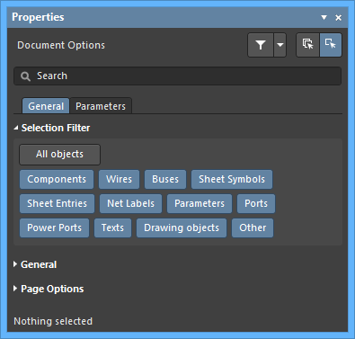
The options in this section of the panel determine which schematic objects may be selected in the workspace.
- All Objects button – select to remove object filtering so that all types of objects may be selected.
- Object buttons – toggle each object button to enable/disable the ability to select that object type.
GeneralExpand折りたたむ
Page OptionsExpand折りたたむ
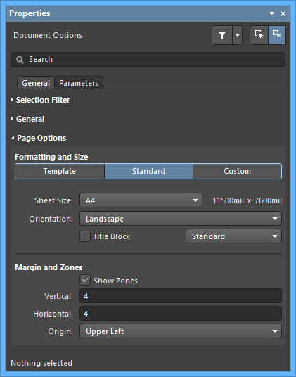
- Formatting and Size
- Template mode – set the page size and format by selecting from a range of predefined schematic sheet templates. The list includes templates found in the location specified in the Data Management - Templates page of the Preferences dialog. Note that a default schematic sheet to be used for new schematic documents can be defined in the System - New Document Defaults page of the Preferences dialog.
- Template – use the drop-down menu to select from a list of standardized page templates, and if required, use the
 button to refresh the template.
- Width/Height – the dimensions of the current page size shown in the current document units (see the General section above).
- Source – displays the template source in the schematic
*.SchDot format.
- Standard mode – set the sheet size to a standard page format.
- Sheet Size – use the drop-down menu to select from a list of standard page dimensions.
- Width/Height – the dimensions of the current page size in the current document units.
- Orientation - use the drop-down to select the desired orientation.
- Title Block - enable this option to display one of two predefined title blocks on the schematic sheet. Use the associated drop-down field to choose from either a Standard or ANSI title block style.
- Custom mode – set the sheet size to specified custom dimensions.
- Width – enter the required sheet width measurement.
- Height – enter the required sheet height measurement.
- Orientation - use the drop-down to select the desired orientation.
- Title Block - enable this option to display one of two predefined title blocks on the schematic sheet. Use the associated drop-down field to choose from either a Standard or ANSI title block style.
- Margin and Zones - defines the size of the sheet border graphics and its zone divisions. Uncheck the Show Zones box to hide the zone divisions in the border graphics.
- Vertical – set the number of divisions (rows) in the vertical sheet margin. The alpha-numeric zone labeling type is defined by the Origin setting.
- Horizontal – set the number of divisions (columns) in the horizontal sheet margin.
- Origin – sets which corner of the document sheet(s) the perimeter zone alpha-numeric indicators will begin from (zone position
A-1 or 1-A).
- Margin Width – set the distance (in the current units) between the page edge and each of the four border lines as indicated by the arrows associated with each entry field.
The following collapsible section contains information about the options and controls available under the panel's Parameters tab:
ParametersExpand折りたたむ
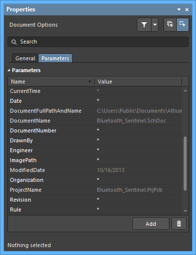
The Properties panel Parameters tab lists all available parameter Name/Value pairs available in the current project document.
- Parameter Name and Value columns – lists the available parameters grouped by type.
- Add – select to add a new parameter to the list. Use the
 button to remove a selected parameter from the list.
When a design object is selected, the panel will present options specific to that object type. The following table lists the object types available for placement on a schematic sheet - click a link to access the properties page for that object.
Schematic Library Support
When the active document is a Schematic Library document (*.SchLib) and no design object is currently selected in the design workspace, the Properties panel presents the Library Options. The following collapsible sections contain information about the options and controls available:
Selection FilterExpand折りたたむ
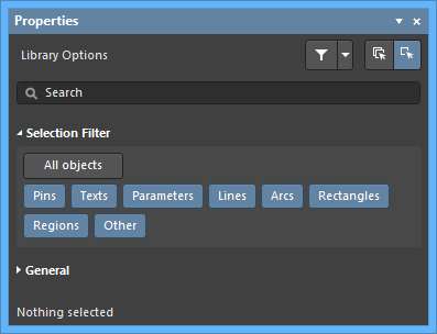
The options in this section of the panel determine which schematic library objects may be selected in the workspace.
- All Objects button – select remove object filtering so that all types of objects may be selected.
- Object buttons – toggle each object button to enable/disable the ability to select that object type.
GeneralExpand折りたたむ
When a design object is selected, the panel will present options specific to that object type. The following table lists the object types available for placement within the library workspace - click a link to access the properties page for that object.
PCB Support
When the active document is a PCB document (*.PcbDoc) and when no design object is currently selected in the design workspace, the Properties panel presents the Board mode. The following collapsible sections contain information about the options and controls available:
Selection FilterExpand折りたたむ
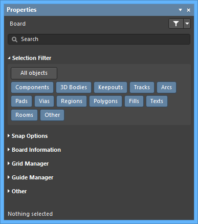
The options in this section of the panel determine which PCB objects may be selected in the workspace.
- All Objects button – select remove object filtering so that all types of objects may be selected.
- Object buttons – toggle each object button to enable/disable the ability to select that object type.
Snap OptionsExpand折りたたむ
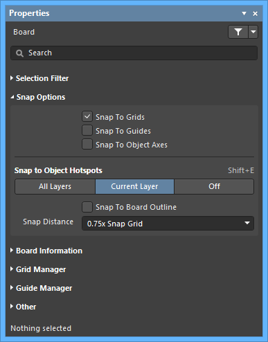
- Snap To Grids - enable this option to allow the cursor to snap to the default Cartesian grid defined for the board.
- Snap To Guides - when checked, the cursor will snap (jump) to guide lines.
- Snap To Object Axes - enable this option to allow the cursor to snap to dynamic alignment guides created through proximity to the hotspot(s) of placed objects.
- Snap to Object Hotspots - select whether you want to snap to objects' hotspots on:
- All Layers - enable this option to allow the cursor to snap to any electrical object on any visible layer.
- Current Layer - enable this option to allow the cursor to only recognize and snap to objects placed on the currently selected layer.
- Off - enable to turn off snapping to hotspots.
- Snap To Board Outline - enable this option to allow the cursor to snap to the board outline. This option can be useful for dimensioning a PCB, particularly when the board corners or vertices are off the Snap Grid.
- Snap Distance - set the distance at which the preview cursor will snap on to the targets outlined above.
Board InformationExpand折りたたむ
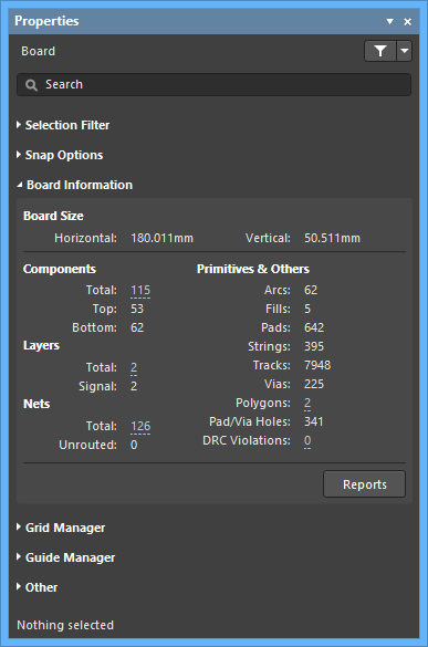
- Board Size - displays the horizontal and vertical board dimensions.
- Components/Layers/Nets/Primitives & Others - displays information for each listed category such as the total number of the listed item.
- Reports - click to open the Board Report dialog in which you can specify the content to be included when generating a detailed report for the board.
Grid ManagerExpand折りたたむ
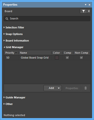
- Grid - lists the current grids set for the board.
- Priority - in the workspace, priority is distinguished by drawing order. The highest priority grid (priority
1) will be drawn in front of all other grids, then the grid with priority level 2, etc., down to the default Global Board Snap Grid, which is drawn behind all other custom grids.
- Name - displays the name of the grid.
- Color - click to open a drop-down to set/change the color of the associated grid.
- Comp - enable to apply the selected grid to only components.
- Non Comp - enable to apply the selected grid to objects that are not components.
- Add
- Add Cartesian Grid - click to add a Cartesian grid.
- Add Polar Grid - click to add a Polar grid. Polar grids enable you to more easily design non-rectangular features and boards.
- Properties - click to open the respective grid editor dialog (Cartesian Grid Editor or Polar Grid Editor) to modify properties for the selected grid.
- - click to delete the currently selected grid.
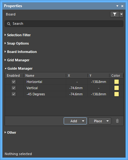
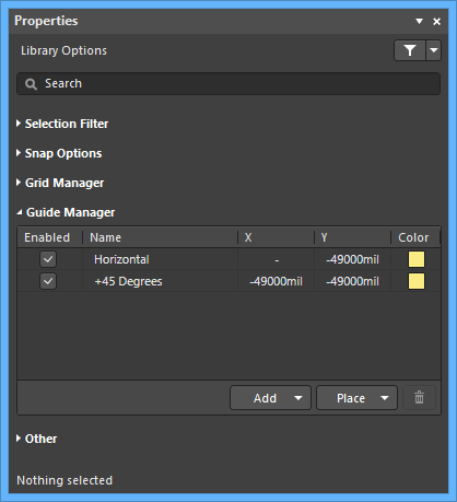
Guide ManagerExpand折りたたむ
- Grid - lists the current grids set for the board.
- Enabled - whether the guide is visible in the workspace (checked) or not (unchecked).
- Name - the name of the guide.
- X - the x-coordinate (where applicable) specified in the workspace that the guide is to pass through or point is to be located at.
- Y - the y-coordinate (where applicable) specified in the workspace that the guide is to pass through or point is to be located at.
A coordinate can be defined by clicking on the relevant field then entering the value. Alternatively, and where applicable/available, click

to the right of the field, then specify the required point directly in the PCB workspace.
- Color - click to open a drop-down to set/change the color of the associated guide.
- Add - click to add a new snap guide or snap point. Choose the corresponding command for the required guide type from the associated menu; an entry for the new guide/point will be added to the grid. The following guide types are available:
- Add Horizontal Guide - use this command to add a horizontal guideline at the desired Y-coordinate location in the workspace.
- Add Vertical Guide - use this command to add a vertical guideline at the desired X-coordinate location in the workspace.
- Add +45 Guide - use this command to add a 45 degree (
y=x) guideline that passes through the desired X,Y coordinate location in the workspace.
- Add -45 Guide - use this command to add a -45 degree (
y=-x) guideline that passes through the desired X,Y coordinate location in the workspace.
- Add Snap Point - use this command to add a point snap guide. This is a hotspot that you manually mark within the confines of the default snap grid. During an interactive process such as placing or moving an object, that objects' hotspot will 'snap' to a point snap guide when it passes into close proximity with it.
- Place - click to place a guide. Select the guide type from the drop-down:
- Place Horizontal Guide - use this command to place a horizontal guideline at the desired Y-coordinate location in the workspace.
- Place Vertical Guide - use this command to place a vertical guideline at the desired X-coordinate location in the workspace.
- Place +45 Guide - use this command to place a 45 degree (
y=x) guideline that passes through the desired X,Y coordinate location in the workspace.
- Place -45 Guide - use this command to place a -45 degree (
y=-x) guideline that passes through the desired X,Y coordinate location in the workspace.
- Place Snap Point - use this command to place a point snap guide. This is a hotspot that you manually mark within the confines of the default snap grid. During an interactive process such as placing or moving an object, that objects' hotspot will 'snap' to a point snap guide when it passes into close proximity with it.
- - click to delete the currently selected guide.
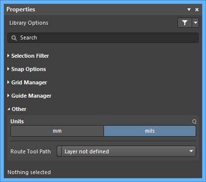
OtherExpand折りたたむ
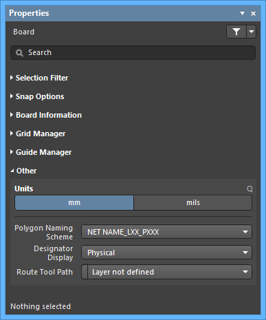
- Units - use to select the default measurement units for the current PCB document. Default units are used to display any distance related information on screen or in reports. The default units are always used if a unit's suffix (mm or mil) is not entered when specifying any distance related information.
- Polygon Naming Scheme - select a naming system from the dropdown menu. There are four choices of naming templates:
NET NAME_LXX_PXXXLXX_NET NAME_PXXXNET NAME_LAYER NAME_PXXXLAYER NAME_NET NAME_PXXX
where:
NET NAME - name of the net to which the polygon is connected. If the polygon is not connected to a net, the name NONET is used.LAYER NAME - user-defined name of that layer from the Layer Stack Manager.LXX - system assigned copper layer number based on the current order of layers in the Layer Stack Manager where Top Layer is L01. This value is updated whenever the order of copper layers is changed.PXXX - system-assigned numerical index; unique for each polygon on the board.
Design changes, such as moving a layer in the layer stack, renaming a net,l or changing the naming scheme will result in the automatic name changing. Affected design rules are automatically updated.
- Designator Display - use this field to determine how designators are to be displayed. It can be difficult positioning the designator strings in a multi-channel design, as they can end up being quite long. As well as choosing a naming option that results in a short name, another option is to display just the original, logical component designation instead. For example, C30_CIN1 would display as C30. This would of course necessitate some other notation being added to the board to indicate the separate channels, such as a box being drawn around each channel on the component overlay. The following options are available:
- Physical - choose to display the physical designators. These are the designators displayed on the compiled tab views of the schematic source documents. For multi-channel designs, designator format is determined by the Designator Format field on the Multi-Channel tab of the Project Options dialog. Physical designators are unique, e.g., R1_CH1.
- Logical - choose to display the logical designators. These are the designators displayed on the Editor tab views of the schematic source documents. Logical designators are not unique; for example, the R1_CH1 physical designator will become simply R1.
- Route Tool Path - use the drop-down to choose the mechanical layer (from all those currently enabled for use in the design) on which to define the route tool path for the board.
When a design object is selected, the panel will present options specific to that object type. The following table lists the object types available for placement within a PCB document - click a link to access the properties page for that object.
PCB Library Support
When the active document is a PCB Library document (*.PcbLib) and when no design object is currently selected in the design workspace, the Properties panel presents the Library Options. The following collapsible sections contain information about the options and controls available:
Selection FilterExpand折りたたむ
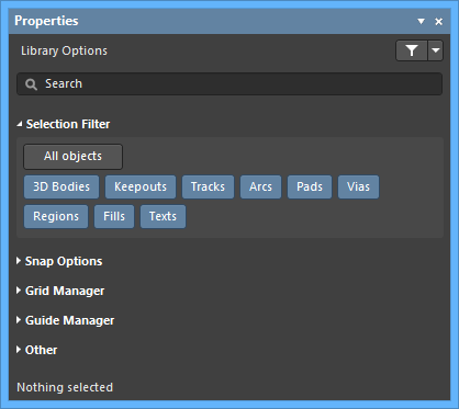
The options in this section determine which PCB library objects may be selected in the workspace.
- All Objects button – select remove object filtering so that all types of objects may be selected.
- Object buttons – toggle each object button to enable/disable the ability to select that object type.
Snap OptionsExpand折りたたむ
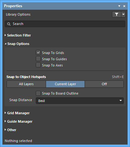
- Snap To Grids - enable this option to allow the cursor to snap to the default Cartesian grid defined for the board.
- Snap To Guides - when checked, the cursor will snap (jump) to guide lines.
- Snap To Axes - enable this option to allow the cursor to snap to dynamic alignment guides created through proximity to the hotspot(s) of placed objects.
- Snap to Object Hotspots - select whether you want to snap to objects' hotspots on:
- All Layers - enable this option to allow the cursor to snap to any electrical object on any visible layer.
- Current Layer - enable this option to allow the cursor to only recognize and snap to objects placed on the currently selected layer.
- Off - enable to turn off snapping to hotspots.
- Snap To Board Outline - enable this option to allow the cursor to snap to the board outline. This option can be useful for dimensioning, particularly when the board corners or vertices are off the Snap Grid.
- Snap Distance - set the distance at which the preview cursor will snap on to the targets outlined above.
Grid ManagerExpand折りたたむ

- Grid - lists the current grids set for the board.
- Priority - in the workspace, priority is distinguished by drawing order. The highest priority grid (priority
1) will be drawn in front of all other grids, then the grid with priority level 2, etc., down to the default Global Board Snap Grid, which is drawn behind all other custom grids.
- Name - displays the name of the grid.
- Color - click to open a drop-down to set/change the color of the associated grid.
- Enabled - check to enable the associated grid.
- Add
- Add Cartesian Grid - click to add a Cartesian grid.
- Add Polar Grid - click to add a Polar grid. Polar grids enable you to more easily design non-rectangular features and boards.
- Properties - click to open the respective grid editor dialog (Cartesian Grid Editor or Polar Grid Editor) to modify properties for the selected grid.
- - click to delete the currently selected grid.
Guide ManagerExpand折りたたむ
- Grid - lists the current grids set for the board.
- Enabled - whether the guide is visible in the workspace (checked) or not (unchecked).
- Name - the name of the guide.
- X - the x-coordinate (where applicable) specified in the workspace that the guide is to pass through or point is to be located.
- Y - the y-coordinate (where applicable) specified in the workspace that the guide is to pass through or point is to be located.
A coordinate can be defined by clicking on the relevant field then entering the value. Alternatively, and where applicable/available, click
to the right of the field, then specify the required point directly in the PCB Library workspace.
- Color - click to open a drop-down to set/change the color of the associated guide.
- Add - click to add a new snap guide or snap point. Choose the corresponding command for the required guide type from the associated menu; an entry for the new guide/point will be added to the grid. The following guide types are available:
- Add Horizontal Guide - use this command to add a horizontal guideline at the desired Y-coordinate location in the workspace.
- Add Vertical Guide - use this command to add a vertical guideline at the desired X-coordinate location in the workspace.
- Add +45 Guide - use this command to add a 45 degree (
y=x) guideline that passes through the desired X,Y coordinate location in the workspace.
- Add -45 Guide - use this command to add a -45 degree (
y=-x) guideline that passes through the desired X,Y coordinate location in the workspace.
- Add Snap Point - use this command to add a point snap guide. This is a hotspot that you manually mark within the confines of the default snap grid. During an interactive process such as placing or moving an object, that objects' hotspot will 'snap' to a point snap guide when it passes into close proximity with it.
- Place - click to place a guide. Select the guide type from the drop-down:
- Place Horizontal Guide - use this command to place a horizontal guideline at the desired Y-coordinate location in the workspace.
- Place Vertical Guide - use this command to place a vertical guideline at the desired X-coordinate location in the workspace.
- Place +45 Guide - use this command to place a 45 degree (
y=x) guideline that passes through the desired X,Y coordinate location in the workspace.
- Place -45 Guide - use this command to place a -45 degree (
y=-x) guideline that passes through the desired X,Y coordinate location in the workspace.
- Place Snap Point - use this command to place a point snap guide. This is a hotspot that you manually mark within the confines of the default snap grid. During an interactive process such as placing or moving an object, that objects' hotspot will 'snap' to a point snap guide when it passes into close proximity with it.
- - click to delete the currently selected guide.
OtherExpand折りたたむ
- Units - use to select the default measurement units for the current PCB Library document. Default units are used to display any distance related information on screen or in reports. The default units are always used if a unit's suffix (mm or mil) is not entered when specifying any distance related information.
- Route Tool Path - use the drop-down to choose the mechanical layer (from all those currently enabled for use in the design) on which to define the route tool path for the board.
When a design object is selected, the panel will present options specific to that object type. The following table lists the object types available for placement within the library workspace - click a link to access the properties page for that object.
Interactive Routing Support
When the active document is a PCB document (*.PcbDoc) and you are currently using the interactive routing tool, the Properties panel presents options pertinent to that tool. The following collapsible sections contain information about the options and controls available:
Net InformationExpand折りたたむ
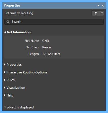
- Net Name - displays the name of the net to which the interactive routing is connected.
- Net Class - displays the net class that the interactive routing belongs to (if it is a member of a net class).
- Length - displays the length.
PropertiesExpand折りたたむ
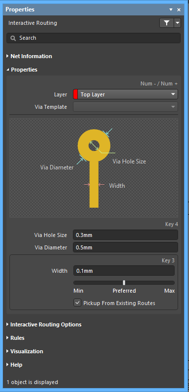
- Layer - use the drop-down to specify on which layer the routing is located.
- Via Template - if the via is associated with a template, the template name is displayed here.
- Via Hole Size - specify the via hole size.
- Via Diameter - specify the via hole diameter.
- Width - specify the width. Use the slider to specify the width. Farther to the left (Min) signifies that the design rule minimum width defined for the current net will be used. Preferred signifies that the design rule preferred width defined for the current net will be used. Farther to the right (Max) signifies that the design rule maximum width defined for the current net will be used.
- Pickup From Existing Routes - enable to use the existing track width when routing from a placed track. In other words, even if the current routing width is different to the existing track, the existing track width will be adopted when you continue the route from it.
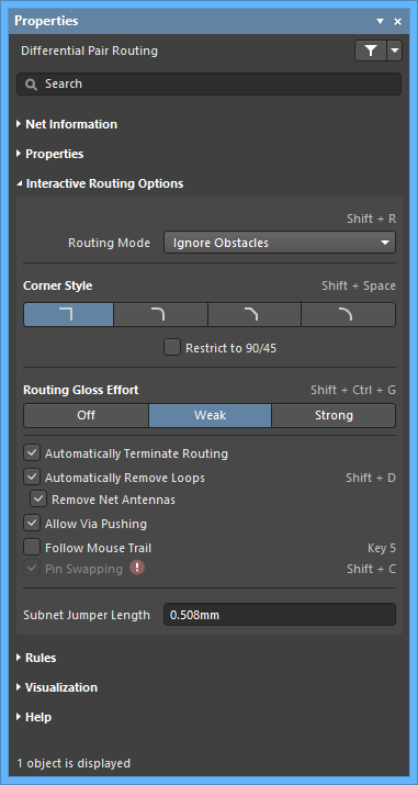
Interactive Routing OptionsExpand折りたたむ
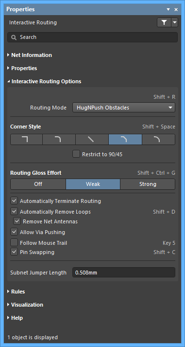
- Routing Mode - use the drop-down to select the desired routing mode. The following choices are available:
- Ignore Obstacles - select to ignore existing objects (routing can be freely placed). Violations are highlighted.
- Walkaround Obstacles - select to have the Interactive Router route around existing tracks, pads and vias. If this mode cannot walk around an obstacle without causing a violation, an indicator appears to show that the route is blocked.
- Push Obstacles - select to have the Interactive Router move existing tracks out of the way. This mode also can push vias to make way for the new routing. If this mode cannot push an obstacle without causing a violation, an indicator appears to show that the route is blocked.
- HugNPush Obstacles - select to have the Interactive Router hug existing tracks, pads, and vias as closely as possible and, where necessary, push obstacles to continue the route. If this mode cannot hug or push an obstacle without causing a violation, an indicator appears to show that the route is blocked.
- Stop At First Obstacle - in this mode, the routing engine will stop at the first obstacle that gets in the way.
- AutoRoute Current Layer - select to enable auto-routing only on the current layer.
- AutoRoute MultiLayer - select to enable auto-routing on multiple layers.
You can switch routing modes on-the-fly using Shift+R during routing.
- Corner Style - select the desired routing corner style.
- Restrict to 90/45 - enable to restrict the routing to 90 degrees and 45 degrees only.
- Routing Gloss Effort - select the desired gloss level from the following choices:
- Off - in this mode, glossing is essentially disabled. Note, however, that cleanup is still run after routing/dragging occurs to eliminate, for example, overlapping track segments. This mode is typically useful at the end stage of board layout when the ultimate level of fine-tuning is required (for example, when manually dragging tracks, cleaning pad entries, etc.).
- Weak - in this mode, a low level of glossing is applied with the Interactive Router considering only those tracks directly connected to or in the area of the tracks that you are currently routing (or tracks/vias being dragged). This mode of glossing is typically useful for fine-tuning track layout or when dealing with critical traces.
- Strong - in this mode, a high level of glossing is applied with the Interactive Router looking for shortest paths, smoothing out tracks, etc. This mode of glossing is typically useful in the early stages of the layout process when the aim is to get a good amount of the board routed quickly.
- Automatically Terminate Routing - when enabled, when you complete a route to the target pad, the routing tool does not continue in routing mode from the target pad but rather resets and is ready for you to click on the next source pad from which to route. If this option is disabled, after you route to the target pad, the tool will remain in routing mode and uses the previous target pad as the source for the next route.
- Automatically Remove Loops - enable to automatically remove any redundant loops that are created during manual routing. This allows you to re-route a connection without having to manually remove redundant tracks. However, there are times when you need to route nets such as power nets and you need loops. You can toggle this option for a selected net by using the hotkey Shift+D to override this global setting for the same net.
- Remove Net Antennas - enable this option to remove any track or arc end that is not connected to any other primitive and forms an antenna.
- Allow Via Pushing - check this option to allow pushing a Via when in Push Obstacles or HugNPush Obstacles mode.
- Follow Mouse Trail - enable this option to activate routing through the mouse trail.
- Pin Swapping - check this option to enable pin swapping. A
 appears when a project compilation is required.
- Subnet Jumper Length - specify the desired Subnet Jumper length.
RulesExpand折りたたむ
VisualizationExpand折りたたむ
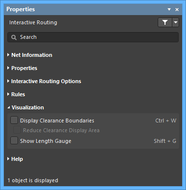
- Display Clearance Boundaries - enable to have the no-go clearance area defined by the existing objects and the applicable clearance rule displayed as shaded polygons within a local viewing circle. This option is not available in the Ignore Obstacles routing mode.
- Reduce Clearance Display Area - enable to use a smaller clearance boundary. This option is available only when the Display Clearance Boundaries option is enabled.
- Show Length Gauge - enable to display the length gauge.
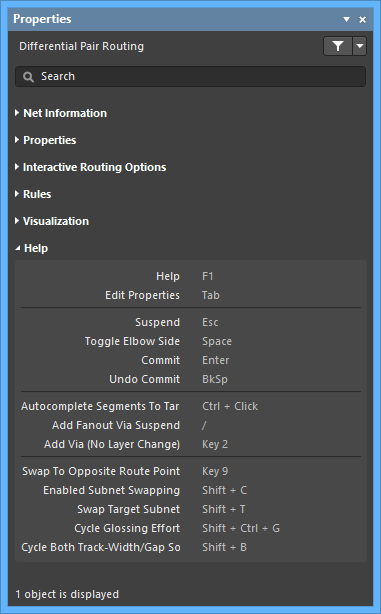
HelpExpand折りたたむ
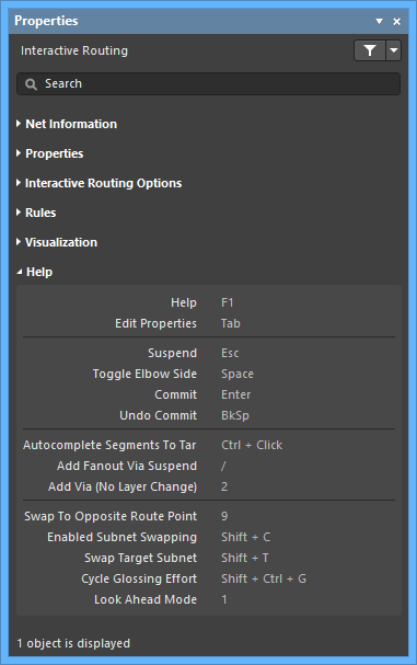
- The Help section displays some of the shortcuts that are available while Interactive Routing.
Interactive Differential Pair Routing Support
When the active document is a PCB document (*.PcbDoc) and you are currently using the interactive differential pair routing tool, the Properties panel presents options pertinent to that tool. The following collapsible sections contain information about the options and controls available.
Net InformationExpand折りたたむ
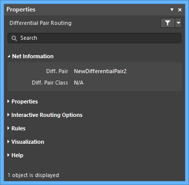
- Diff. Pair - displays the differential pair name.
- Diff. Pair Class - displays the differential pair class to which the routing belongs (if it is a member of a differential pair class).
PropertiesExpand折りたたむ
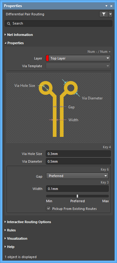
- Layer - use the drop-down to specify on which layer the routing is located.
- Via Template - if the via is associated with a template, the template name is displayed here.
- Via Hole Size - specify the via hole size.
- Via Diameter - specify the via hole diameter.
- Gap
- Min - select to specify the minimum permissible clearance between primitives on different nets within the same differential pair.
- Preferred - select to specify the preferred clearance between primitives on different nets within the same differential pair.
- Max - select to specify the maximum permissible clearance between primitives on different nets within the same differential pair.
- Width - specify the width. Use the slider bar to specify the width. Farther to the left (Min) signifies that the design rule minimum width defined for the current net will be used. Preferred signifies that the design rule preferred width defined for the current net will be used. Farther to the right (Max) signifies that the design rule maximum width defined for the current net will be used.
- Pickup From Existing Routes - enable to use the existing track width when routing from a placed track. In other words, even if the current routing width is different to the existing track, the existing track width will be adopted when you continue the route from it.
Interactive Routing OptionsExpand折りたたむ
- Routing Mode - use the drop-down to select the desired routing mode. The following choices are available:
- Ignore Obstacles - select to ignore existing objects (routing can be freely placed). Violations are highlighted.
- Walkaround Obstacles - select to have the Interactive Router route around existing tracks, pads and vias. If this mode cannot walk around an obstacle without causing a violation, an indicator appears to show that the route is blocked.
- Push Obstacles - select to have the Interactive Router move existing tracks out of the way. This mode also can push vias to make way for the new routing. If this mode cannot push an obstacle without causing a violation, an indicator appears to show that the route is blocked.
- HugNPush Obstacles - select to have the Interactive Router hug existing tracks, pads, and vias as closely as possible and, where necessary, push obstacles to continue the route. If this mode cannot hug or push an obstacle without causing a violation, an indicator appears to show that the route is blocked.
- Stop At First Obstacle - in this mode, the routing engine will stop at the first obstacle that gets in the way.
- AutoRoute Current Layer - select to enable auto-routing only on the current layer.
- AutoRoute MultiLayer - select to enable auto-routing on multiple layers.
You can switch routing modes on-the-fly using Shift+R during routing.
- Corner Style - select the desired routing corner style.
- Restrict to 90/45 - enable to restrict the routing to 90 degrees and 45 degrees only.
- Routing Gloss Effort - select the desired gloss level from the following choices:
- Off - in this mode, glossing is essentially disabled. Note, however, that cleanup is still run after routing/dragging occurs to eliminate, for example, overlapping track segments. This mode is typically useful at the end stage of board layout when the ultimate level of fine-tuning is required (for example, when manually dragging tracks, cleaning pad entries, etc.).
- Weak - in this mode, a low level of glossing is applied with the Interactive Router considering only those tracks directly connected to or in the area of the tracks that you are currently routing (or tracks/vias being dragged). This mode of glossing is typically useful for fine-tuning track layout or when dealing with critical traces.
- Strong - in this mode, a high level of glossing is applied with the Interactive Router looking for shortest paths, smoothing out tracks, etc. This mode of glossing is typically useful in the early stages of the layout process when the aim is to get a good amount of the board routed quickly.
- Automatically Terminate Routing - when enabled, when you complete a route to the target pad, the routing tool does not continue in routing mode from the target pad but rather resets and is ready for you to click on the next source pad from which to route. If this option is disabled, after you route to the target pad, the tool will remain in routing mode and use the previous target pad as the source for the next route.
- Automatically Remove Loops - enable to automatically remove any redundant loops that are created during manual routing. This allows you to re-route a connection without having to manually remove redundant tracks. However, there are times when you need to route nets such as power nets and you need loops - you can toggle this option for a selected net by using the hotkey Shift+D to override this global setting for the same net.
- Remove Net Antennas - enable this option to remove any track or arc end that is not connected to any other primitive and forms an antenna.
- Allow Via Pushing - check this option to allow pushing a Via when in Push Obstacles or HugNPush Obstacles mode.
- Follow Mouse Trail - enable this option to activate routing through the mouse trail.
- Pin Swapping - check this option to enable pin swapping. A appears when a project compilation is required.
- Subnet Jumper Length - specify the desired Subnet Jumper length.
RulesExpand折りたたむ
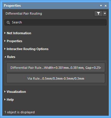
- Differential Pair Rule - click to open the Edit PCB Rule dialog to view/edit the rule.
- Via Rule - click to open the Edit PCB Rule dialog to view/edit the rule.
VisualizationExpand折りたたむ
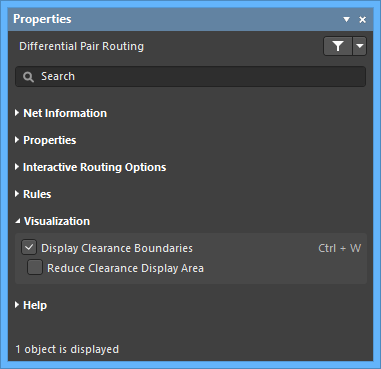
- Display Clearance Boundaries - enable this option to have the no-go clearance area defined by the existing objects and the applicable clearance rule displayed as shaded polygons within a local viewing circle. This option is not available in the Ignore Obstacles routing mode.
- Reduce Clearance Display Area - enable this option to use a smaller clearance boundary. This option is available only when the Display Clearance Boundaries option is enabled.
HelpExpand折りたたむ
- The Help section displays some of the shortcuts that are available while routing.
Interactive Multi-Routing Support
When the active document is a PCB document (*.PcbDoc) and you are currently using the interactive multi-routing tool, the Properties panel presents options pertinent to that tool. The following collapsible sections contain information about the options and controls available:
PropertiesExpand折りたたむ
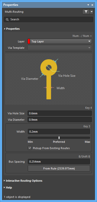
- Layer - use the drop-down to specify on which layer the routing is located.
- Via Template - if the via is associated with a template, the template name is displayed here.
- Via Hole Size - specify the via hole size.
- Via Diameter - specify the via hole diameter.
- Width - specify the width. Use the slider bar to specify the width. Farther to the left (Min) signifies that the design rule minimum width defined for the current net will be used. Preferred signifies that the design rule preferred width defined for the current net will be used. Farther to the right (Max) signifies that the design rule maximum width defined for the current net will be used.
- Pickup From Existing Routes - enable to use the existing track width when routing from a placed track. In other words, even if the current routing width is different to the existing track, the existing track width will be adopted when you continue the route from it.
- Bus Spacing - enter the desired bus routing.
- From Rule - click to assign bus spacing based on the existing design rule.
Interactive Routing OptionsExpand折りたたむ
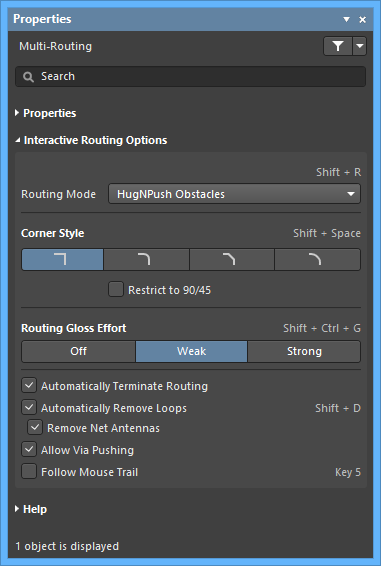
- Routing Mode - use the drop-down to select the desired routing mode. The following choices are available:
- Ignore Obstacles - select to ignore existing objects (routing can be freely placed). Violations are highlighted.
- Walkaround Obstacles - select to have the Interactive Router route around existing tracks, pads and vias. If this mode cannot walk around an obstacle without causing a violation, an indicator appears to show that the route is blocked.
- Push Obstacles - select to have the Interactive Router move existing tracks out of the way. This mode also can push vias to make way for the new routing. If this mode cannot push an obstacle without causing a violation, an indicator appears to show that the route is blocked.
- HugNPush Obstacles - select to have the Interactive Router hug existing tracks, pads, and vias as closely as possible and, where necessary, push obstacles to continue the route. If this mode cannot hug or push an obstacle without causing a violation, an indicator appears to show that the route is blocked.
- Stop At First Obstacle - in this mode, the routing engine will stop at the first obstacle that gets in the way.
- AutoRoute Current Layer - select to enable auto-routing only on the current layer.
- AutoRoute MultiLayer - select to enable auto-routing on multiple layers.
You can switch routing modes on-the-fly using Shift+R during routing.
- Corner Style - select the desired routing corner style.
- Restrict to 90/45 - enable to restrict the routing to 90 degrees and 45 degrees only.
- Routing Gloss Effort - select the desired gloss level from the following choices:
- Off - in this mode, glossing is essentially disabled. Note, however, that cleanup is still run after routing/dragging occurs to eliminate, for example, overlapping track segments. This mode is typically useful at the end stage of board layout when the ultimate level of fine-tuning is required (for example, when manually dragging tracks, cleaning pad entries, etc.).
- Weak - in this mode, a low level of glossing is applied with the Interactive Router considering only those tracks directly connected to or in the area of the tracks that you are currently routing (or tracks/vias being dragged). This mode of glossing is typically useful for fine-tuning track layout or when dealing with critical traces.
- Strong - in this mode, a high level of glossing is applied with the Interactive Router looking for shortest paths, smoothing out tracks, etc. This mode of glossing is typically useful in the early stages of the layout process when the aim is to get a good amount of the board routed quickly.
- Automatically Terminate Routing - when enabled, when you complete a route to the target pad, the routing tool does not continue in routing mode from the target pad but rather resets and is ready for you to click on the next source pad from which to route. If this option is disabled, after you route to the target pad, the tool will remain in routing mode and use the previous target pad as the source for the next route.
- Automatically Remove Loops - enable to automatically remove any redundant loops that are created during manual routing. This allows you to re-route a connection without having to manually remove redundant tracks. However, there are times when you need to route nets such as power nets and you need loops. You can toggle this option for a selected net by using the Shift+D hotkey to override this global setting for the same net.
- Remove Net Antennas - enable this option to remove any track or arc end that is not connected to any other primitive and forms an antenna.
- Allow Via Pushing - check this option to allow pushing a Via when in Push Obstacles or HugNPush Obstacles mode.
- Follow Mouse Trail - enable this option to activate routing through the mouse trail.
HelpExpand折りたたむ
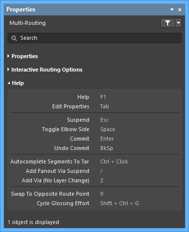
- The Help section displays some of the shortcuts that are available while routing.
Interactive Length Tuning Support
When the active document is a PCB document (*.PcbDoc) and you are currently using the interactive length tuning tool to place an accordion or have interactively selected an accordion object, the Properties panel presents options pertinent to that accordion.
The following collapsible sections contain information about the options and controls available.
Net InformationExpand折りたたむ
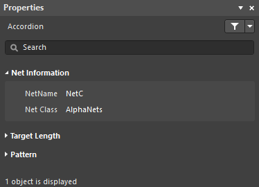
- Net Name - name of the net to which the accordion is connected. Displays the * character if multiple accordions are currently selected.
- Net Class - net class to whichthis net belongs (if it is a member of a net class).
Target LengthExpand折りたたむ
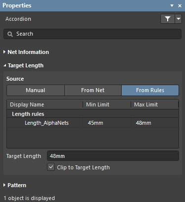
The objective of placing an accordion is to achieve a specific target length for the route whose length is being tuned. That target length is displayed in the Target Length field. The Source buttons are used to control from where that target length value is sourced; the grid below the buttons displays details about the current choice.
- Source - source of the maximum length value that the Interactive Length Tuning command is attempting to achieve.
- Manual - required length can be entered directly into the Target Length field. A list of Recently Used Lengths will appear when this mode is selected. Click to use one of these lengths.
- From Net - required length is defined by selecting a net name. The list of net names region will include all nets in the design.
- From Rules - applicable Length and/or Matched Length design rules will be listed. If the net is targeted by multiple rules, the most conservative rule is chosen.
- Source List - this grid region changes based on the user-selected Source mode as described above.
- Target Length - overall length that the Interactive Length Tuning command is attempting to achieve with the addition of the accordion being placed.
- Clip to Target Length - if enabled, the accordion length is automatically clipped once the target length is achieved.
PatternExpand折りたたむ
HelpExpand折りたたむ
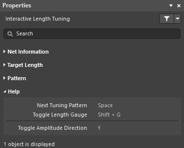
- The Help section displays some of the shortcuts that are available while interactive length tuning.
Refer to the
object page to learn more about the Accordion object.
Refer to the
Length Tuning page to learn more about interactive length tuning.
Interactive Differential Pair Length Tuning Support
When the active document is a PCB document (*.PcbDoc) and you are currently using the interactive differential pair length tuning tool, the Properties panel presents options pertinent to that tool. The following collapsible sections contain information about the options and controls available:
Differential Pair InformationExpand折りたたむ
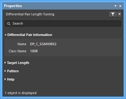
- Name - the name of the differential pair.
- Class Name - the class to which the pair belongs (if available).
Target LengthExpand折りたたむ
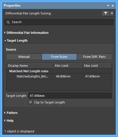
- Source
- Manual - use the manual mode to enter the length in the Target Length field. The Recently Used Lengths region keeps track of the values you have typed in so that you can easily use them again.
- From Rules - one or both of the Length and Matched Length design rules must be defined to use this mode. The software will then obey the most stringent combination of these rules. Double-click on a rule listed in the Display Name region to examine its properties in detail.
- From Diff. Pairs - lists the differential pairs and their lengths on the current PCB. The currently selected differential pair length value is shown in the Target Length field.
- Target Length - enter the target length.
- Clip to Target Length - enable to ensure that the final length does not exceed the target length.
PatternExpand折りたたむ
HelpExpand折りたたむ
The Help section displays some of the shortcuts that are available while routing.
Via Shielding Support
When the active document is a PCB document (*.PcbDoc) and you select or double-click on a shielding via, the Properties panel presents options pertinent to that union object. The following collapsible sections contain information about the options and controls available:
The vias in a Via Shielding are members of a Union object. If the Display popup selection dialog option is disabled in the Preferences dialog, a single click on a via in a Via Shielding Union will select just that via. A second click in the same location will select the Via Shielding Union, displaying its properties in the Properties panel.
► See the Add Shielding to Net dialog for more information about the Via Shielding options during initial placement.
► See Via Stitching and Via Shielding for more information about working with Shielding Vias.
After modifying a value in the panel, the message Changes pending, Apply? will appear at the bottom of the panel. You must click Apply for the changes to be made to the design.
Shielding ParametersExpand折りたたむ
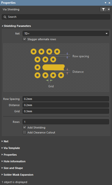
- Net - net to have shielding vias placed around.
- Stagger alternate rows - alternate rows of shielding vias are offset by half of the Grid value when this option is enabled.
- Row Spacing - spacing between rows of shielding vias (edge to edge separation) when the Rows setting is greater than 1.
- Distance - separation from the edge of the shielded net track segments, to the edge of the shielding vias.
- Grid - the distance between the edges of adjacent shielding vias. Shielding vias will not be placed in violation of applicable design rules; if a potential via site would result in a violation then that site is skipped.
- Rows - number of rows of shielding vias.
- Add Shielding - place a polygon over the area occupied by the shielding vias, connected to the net specified in the Via Net field. The polygon is defined in accordance with the applicable Clearance constraint and Polygon Connect Style design rules.
- Add Clearance Cutout - include a polygon cutout around the shielded net, set back from the net by the distance specified in the Distance field. Use this when you require a different clearance from the applicable Clearance constraint design rule.
NetExpand折りたたむ
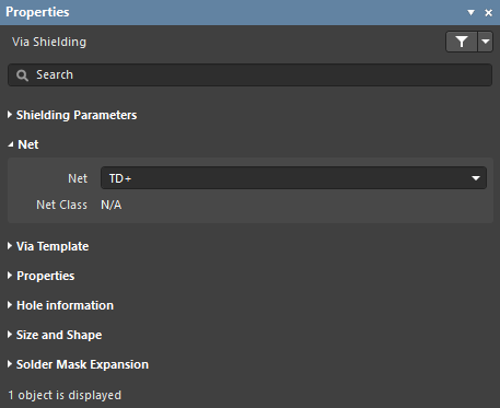
- Net - the net being shielded by the shielding vias.
- Net Class - if the chosen Net is a member of a Net Class, it will be displayed in this field.
Via TemplateExpand折りたたむ
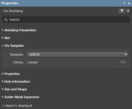
- Template - displays the currently chosen via template. Use the dropdown to change the assigned via template.
- Library - displays to which library the via template is linked and includes the option to Unlink the template from said library.
PropertiesExpand折りたたむ
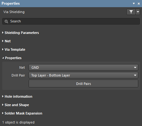
- Net - net that the shielding vias are connected to.
- Drill Pair - the layers on which this via starts and ends.
- Drill Pairs - click this button to open the Drill-Pair Manager dialog that provides controls to configure the required drill pairs for the active layer stack.
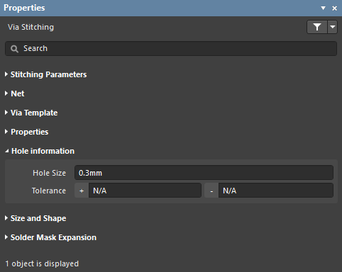
Hole InformationExpand折りたたむ
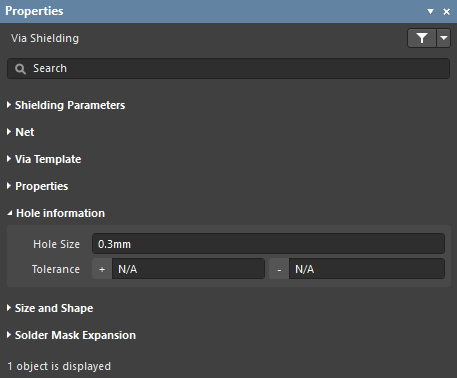
- Hole Size - size of the hole in the shielding vias.
- Tolerance - negative and positive hole size tolerances allowed for the shielding vias.
Size and ShapeExpand折りたたむ
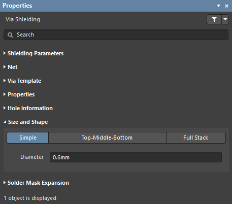
- Size and Shape - vias are one of three styles:
- Simple - the via diameter is the same on all layers
- Top-Middle-Bottom - the via diameter can be specified for the Top layer, Middle (all internal layers), and Bottom layer.
- Full Stack - the via diameter can be specified for every signal layer.
- Diameter - diameter of the shielding vias.
Solder Mask ExpansionExpand折りたたむ
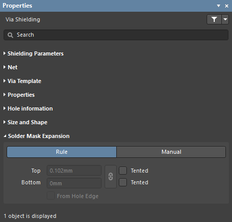
- Rule - enable this option to allow the existing solder mask expansion rule to take effect on the shielding vias. Check the Mask design category from the PCB Rules and Constraints Editor dialog.
- Manual - enable this option to edit the mask expansion values (below) for these shielding vias.
- Top - enter the required mask expansion for the Top Layer.
- Bottom - enter the required mask expansion for the Bottom Layer.
- Top Tented - if this checkbox is enabled, the mask is closed on the Top Layer for these shielding vias.
- Bottom Tented - if this checkbox is enabled, the mask is closed on the Bottom Layer for these shielding vias.
- Linked - if the Linked option is enabled, the same expansion value is used for both the Top and Bottom layers.
- From Hole Edge - enable this option to calculate the mask expansion from the edge of the drill hole instead of the edge of the via donut.
Via Stitching Support
When the active document is a PCB document (*.PcbDoc) and you select or double-click on a stitching via, the Properties panel presents options pertinent to that union object. The following collapsible sections contain information about the options and controls available.
The vias in a Via Stitching are members of a Union object. If the Display popup selection dialog option is disabled in the Preferences dialog, a single click on a via in a Via Stitching Union will select just that via. A second click in the same location will select the Via Stitching Union, displaying its properties in the Properties panel.
► See the Add Stitching to Net dialog for more information about the Via Stitching options during initial placement.
► See Via Stitching and Via Shielding for more information about working with Stitching Vias.
After modifying a value in the panel, the message Changes pending, Apply? will appear at the bottom of the panel. You must click Apply for the changes to be made to the design.
Stitching ParametersExpand折りたたむ
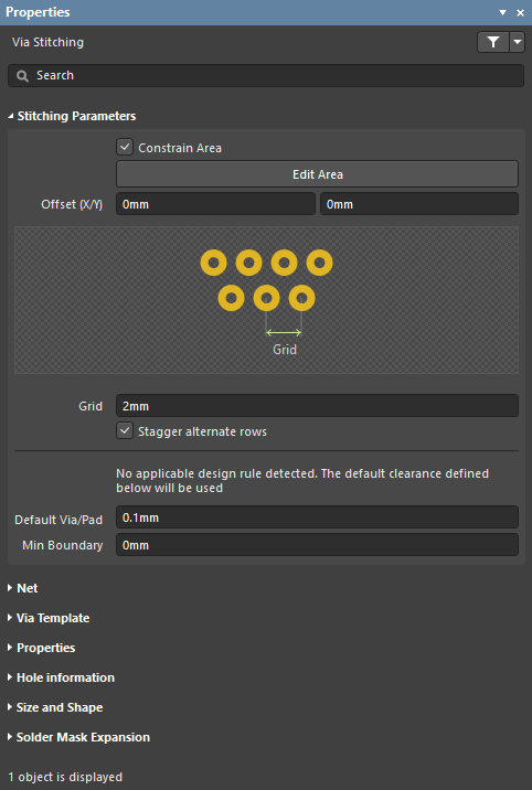
- Constrain Area - enable to constrain via stitching to a specific area. After selecting the option, you will be taken to the design space. After using the cross-hair cursor to define the constrain area, right-click to return to the dialog.
- Edit Area - click to edit the constrain area.
- Offset (X/Y) - enter the X and Y offset distance(s). The stitching pattern will placed within the constrain area, starting at an offset of the specified X and Y amount.
- Grid - the distance between the center of adjacent stitching vias. Stitching vias will not be placed in violation of applicable design rules; if a potential via site would result in a violation that site is skipped.
- Stagger alternate rows - alternate rows of shielding vias are offset by half of the Grid value.
- Default Via/Pad - stitching vias are only placed on potential stitching sites if this much clearance exists. Since potential stitching sites are determined by the stitching grid, it is likely they will be further than apart than this setting.
- Min Boundary - stitching vias are only placed on potential stitching sites if this much clearance exists to the edge of Polygon/Fill/Plane regions.
NetExpand折りたたむ
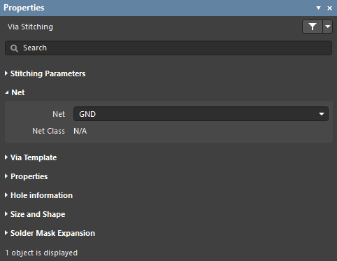
- Net - the net to which the via stitching is currently assigned. Change the net assignment by clicking in the field and choosing a net from the drop down list.
- Net Class - if the chosen Net is a member of a Net Class, it will be displayed in this field.
Via TemplateExpand折りたたむ
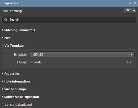
- Template - displays the currently chosen via template. Use the dropdown to change the assigned via template.
- Library - displays to which library the via template is linked and includes the option to Unlink the template from said library.
PropertiesExpand折りたたむ
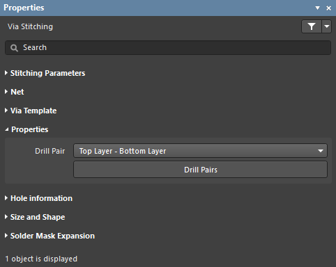
- Drill Pair - the layers on which this via starts and ends.
- Drill Pairs - click this button to open the Drill-Pair Manager dialog that provides controls to configure the required drill pairs for the active layer stack.
Hole InformationExpand折りたたむ
- Hole Size - size of the hole in the stitching vias.
- Tolerance - negative and positive tolerances allowed for the stitching vias.
Size and ShapeExpand折りたたむ
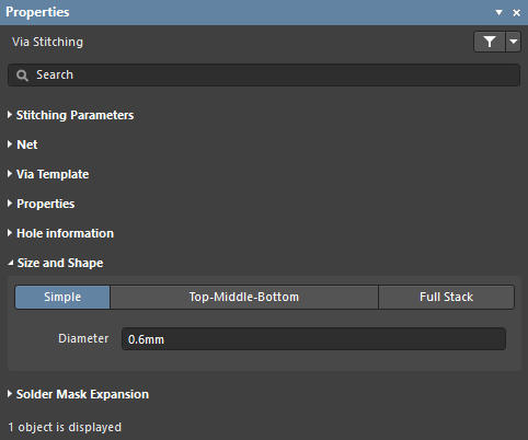
- Size and Shape - vias are one of three styles:
- Simple - the via diameter is the same on all layers
- Top-Middle-Bottom - the via diameter can be specified for the Top layer, Middle (all internal layers), and Bottom layer.
- Full Stack - the via diameter can be specified for every signal layer.
- Diameter - diameter of the stitching vias.
Solder Mask ExpansionExpand折りたたむ
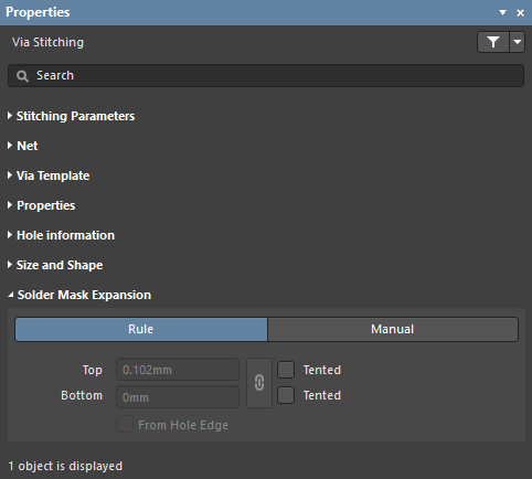
- Rule - enable this option to allow the existing solder mask expansion rule to take effect on the stitching vias. Check the Mask design category from the PCB Rules and Constraints Editor dialog.
- Manual - enable this option to edit the mask expansion values (below) for these stitching vias.
- Top - enter the required mask expansion for the Top Layer.
- Bottom - enter the required mask expansion for the Bottom Layer.
- Top Tented - if this checkbox is enabled, the mask is closed on the Top Layer for these stitching vias.
- Bottom Tented - if this checkbox is enabled, the mask is closed on the Bottom Layer for these stitching vias.
- Linked - if the Linked option is enabled, the same expansion value is used for both the Top and Bottom layers.
- From Hole Edge - enable this option to calculate the expansion from the edge of the drill hole instead of the edge of the via donut.
Multi-board Schematic Support
When the active document is a multi-board schematic document (*.MbsDoc) and when no design object is currently selected in the design workspace, the Properties panel presents the Document Options.
The following collapsible sections contain information about the options and controls available under the panel's General tab.
Selection FilterExpand折りたたむ
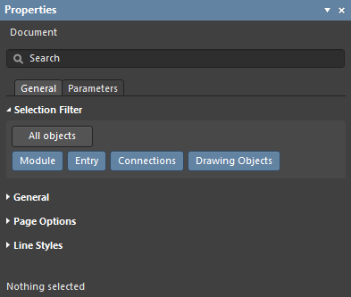
The options in this section of the panel determine which multi-board objects may be selected in the workspace.
- All Objects button – select remove object filtering so that all types of objects may be selected.
- Object buttons – toggle each object button to enable/disable the ability to select that object type.
GeneralExpand折りたたむ
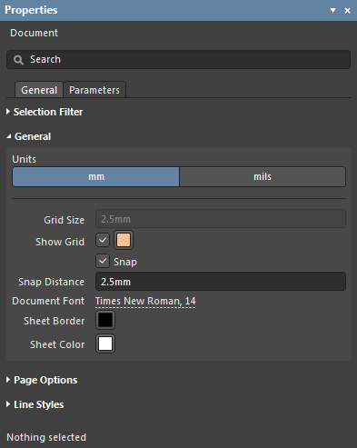
- Units – select the measurement units that apply to the multi-board document and its graphic elements.
- Grid Size – set the measured distance between each sheet grid line. Note that this option is not editable in multi-board documents.
- Show Grid – check to display grid lines at the default Grid Size in the document sheet. Click the associated color button (
 ) to specify the color of the grid lines in the color selector drop-down, which includes options for preset colors, HEX/RGB color values and the graphic selection of color shades.
- Snap – when checked, the ghost/preview cursor will snap (jump) to grid line intersections while the editor is in object placement mode. The cursor will also snap to graphic object vertices (corners, etc.,), line midpoints and circle centers.
- Snap Distance – set the distance at which the preview cursor will snap onto the targets outlined above. The preview cursor changes to an orange dot when a midpoint, vertex, or center is snapped to.
- Document Font – set the font size, style and any additional font attributes that will be used for the text associated with all objects in the document sheet. For any given object, the font settings may be overridden in its corresponding Properties panel mode, which is enabled when that object is selected.
- Sheet Border – click the associated color button to set the zone border line and character color for the document sheet.
- Sheet Color – click the associated color button to set the background color for the document sheet.
Page OptionsExpand折りたたむ
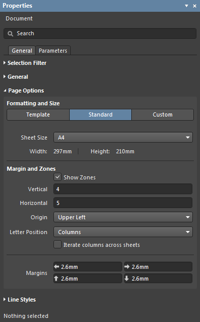
Formatting and Size
- Template mode – set the page size and format by selecting from a range of predefined schematic sheet templates. The list includes templates found in the location specified in the Data Management - Templates page of the Preferences dialog. Note that a default schematic sheet to be used for new multi-board documents may be defined on the System - New Document Defaults page of the Preferences dialog.
- Template – use the drop-down menu to select from a list of standardized page templates, and if required, use the
 button to refresh the template and drawing.
- Width/Height – the dimensions of the current page size shown in the current document units (see the General section above).
- Source – use the browse button (
 ) to navigate to and select an alternative template source in the schematic
 *.SchDot format.
- Standard mode – set the sheet size to a standard page format.
- Sheet Size – use the drop-down menu to select from a list of standard page dimensions.
- Width/Height – the dimensions of the current page size in the current document units.
- Custom mode – set the sheet size to specified custom dimensions.
- Width – enter the required sheet width measurement.
- Height – enter the required sheet height measurement.
Margin and Zones
Defines the size of the sheet border graphics and its zone divisions. Uncheck the Show Zones box to hide the zone divisions in the border graphics.
- Vertical – set the number of divisions (rows) in the vertical sheet margin. The alpha-numeric zone labeling type is defined by the Origin and Letter Position settings.
- Horizontal – set the number of divisions (columns) in the horizontal sheet margin.
- Origin – sets which corner of the document sheet(s) the perimeter zone alpha-numeric indicators will begin from (zone position
A-1 or 1-A).
- Letter Position – set where the letter zone indicators are placed on the document sheet, either in the horizontal perimeter zones (columns) or the vertical zones (rows). Enable Iterate columns across sheets to repeat the columns across all sheets.
- Margins – set the distance (in the current units) between the page edge and each of the four border lines as indicated by the arrows associated with each entry field.
Line StylesExpand折りたたむ
The following collapsible section contains information about the options and controls available under the panel's Parameters tab:
ParametersExpand折りたたむ
When a design object is selected in the workspace, the Properties panel will present options specific to that object type – the panel changes to that object 'mode'. The following table lists the object types available for placement within a multi-board schematic document, where each listed entry links to its associated properties information (Properties panel mode) page.
ActiveBOM Support
When the active document is a BOM document (*.BomDoc), the Properties panel presents the Document Options.
The following collapsible sections contain information about the options and controls available.
GeneralExpand折りたたむ
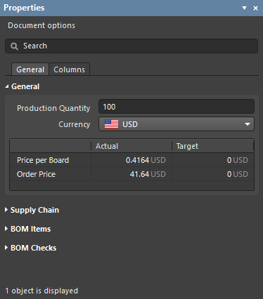
- Production Quantity - the number of boards to be built. It is important to define this field since this is used during supply chain searching to check component availability from the suppliers.
- Currency - the preferred currency to display component prices. Exchange rates for currency conversion are refreshed daily provided you are signed in to your Altium account. When you disconnect from Altium (on the System - Account Management page of the Preferences dialog), access to these updated rates is lost. In this situation, there is an option in the BOM reports dialog to use cached data.
- Price per Board / Order Price grid - Price per Board is the sum of the prices of each individual item detailed in the BOM Items grid; the Order Price grid is this value times the Production Quantity. If target prices have been defined for each BOM Item, the Target column reflects these. To enter a target price for each BOM Item, enable the TargetPrice column on the Columns tab of the panel, then enter the price of each item in the Item grid.
Supply ChainExpand折りたたむ
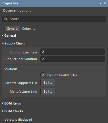
Supply Chain information is presented in the lower region of the ActiveBOM interface, showing a manufacturer component on the left with one or more colored supplier tiles to the right of it. This region displays data when valid supply chain information can be identified for a BOM Item. Each of these Manufacturer & Supplier(s) Details rows is referred to as a Solution. The manufacturer details are abbreviated to MPNs (Manufacturer Part Numbers) and the supplier details are abbreviated to SPNs (Supplier Part Numbers).
- Solutions per Item - the number of manufacturer parts you would like to be located for each BOM Item.
- Suppliers per Solution - the number of suppliers you would like to be located for each manufacturer part.
- Solutions
- Exclude Invalid SPNs - select to exclude invalid SPNs.
- Favorite Suppliers List - opens the Favorite Suppliers dialog in which the overall list of Suppliers can be configured for this BomDoc.
- Manufacturer Link - opens the Define Manufacturer Link Fields dialog in which the schematic component parameters that hold the Manufacturer Name and Manufacturer Part Number are identified. If there are unmanaged parts present in the design (parts not placed from a managed content server that also do not have supplier details), ActiveBOM can query the Altium Parts Provider and attempt to find that part.
BOM ItemsExpand折りたたむ
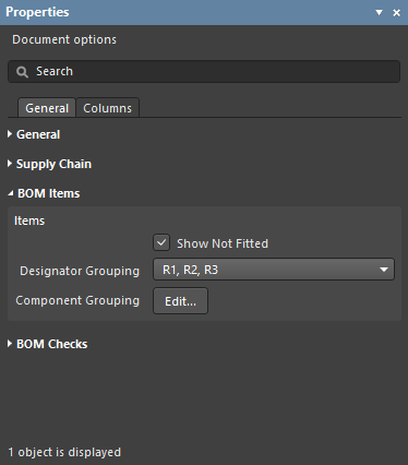
This region is used to configure how the BOM Items should be grouped in the BOM Items grid.
- Items
- Show not Fitted - if the PCB project includes variants and the chosen variant has parts set to Not Fitted, enable this to display the Not Fitted items in the BOM Items grid.
- Designator Grouping - the Base and Consolidated view modes show common parts on a single row in the BOM Items grid. Use this option to configure if the designators are displayed individually or in ranges when a row displays multiple parts.
- Component Grouping - opens the Component Grouping dialog. In Base view or Consolidated view, ActiveBOM identifies components as being the same when they share the same ItemID (managed) or LibRef (unmanaged). Enable parameters in the dialog to further refine how components are to be grouped.
BOM ChecksExpand折りたたむ
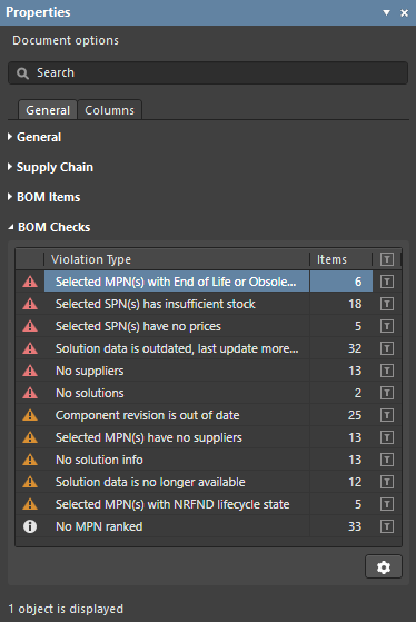
ActiveBOM performs comprehensive checking of each BOM Item and any supply chain data that has been detected for that item.
- Violation Type grid - displays a list of each type and quantity of violations currently present in the BomDoc. Click the filter icon to display only those BOM Items that fail that BOM Check. Note that a BOM Item can fail multiple BOM Checks.
- BOM Checks
 - click the icon to open the BOM Checks dialog in which the Report Mode can be configured for each possible Violation Type.
ColumnsExpand折りたたむ
Draftsman Support
► See the Draftsman Properties panel page.
