
创建线束布局图
在线束设计以接线图的形式捕获完成后,即可创建该设计的物理表示——线束布局图文档(*.LdrDoc)。在Projects面板中将此文档添加到线束项目:在项目条目上单击右键,然后从上下文菜单中选择Add New to Project » Harness Wiring Diagram (或使用主菜单中的File » New » Harness Layout Drawing命令)。
设置线束布局图文档
当文档设计空间中未选中任何对象时,可在Properties面板中配置布局图文档的选项。主要设置包括:
-
在面板General选项卡的General区域中——选择适用于该文档及其图形元素的度量单位,并设置网格以便更轻松地放置对象。Altium Designer 提供三种网格类型:用于导航的可见网格、用于放置的捕捉网格,以及用于辅助创建连接的捕捉距离。
-
在面板General选项卡的Page Options 区域中——配置文档图纸尺寸与标题栏,或从可用的线束布局图模板中选择。

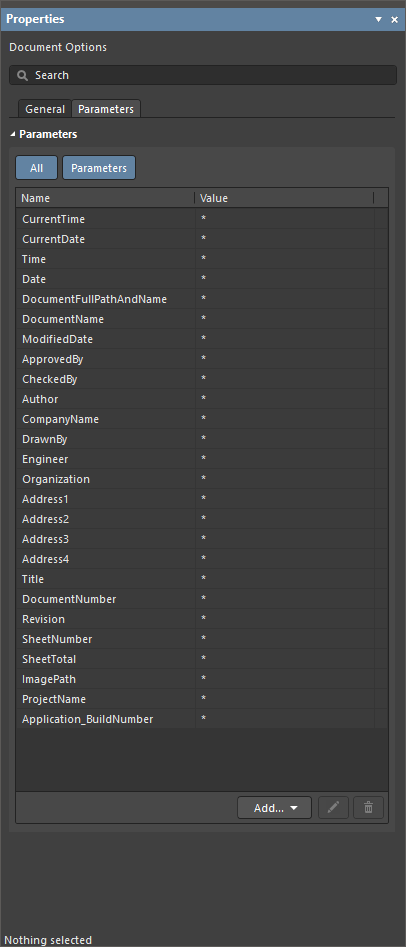
当线束布局图文档中未选中任何对象时,Properties面板的General与Parameters选项卡
从接线图导入数据
从主菜单选择Design » Import Wiring Diagram命令,以从接线图导入设计数据。元件将按接线图中定义的相对位置放置到布局图图纸上。与元件关联的连接点也会在布局图中放置在各元件旁边。

已从接线图导入数据的线束布局图文档
 )中。
)中。
处理元件
初始状态下,每个元件在布局图中以其符号表示。选中设计空间中的元件后,可在Properties 面板中配置已放置元件的属性。元件的Properties 面板包含以下选项卡:
-
General——元件的一般属性,例如位号与注释、位置、模型表示、参数等。
-
Pins——元件引脚列表。
-
Cavities——分配给该元件的插座腔位(socket cavities)的只读视图。腔位分配只能在接线图中修改——了解更多。
-
Associated Parts——允许将热缩管等附加部件分配给该元件。

配置元件的表示方式
当选中元件时,可在Properties 面板(General选项卡下)Model 区域中使用Graphical Symbol / Physical Model 选项,在符号表示(元件的symbol)与 3D 模型投影(元件的footprint)之间切换。使用该区域中的其他设置可进一步配置表示方式。
|
以原理图符号表示的元件 同一元件以其 3D 模型投影表示 |


使用Physical Model表示方式时,可使用Style 选项将模型显示为Solid(无边线)或显示为Wireframe。使用Side下拉列表的选项选择所需的模型视图方向(提供正交与等轴测选项)。下方图片展示了部分设置及其在设计空间中的对应效果。


 )。
)。
在线束布局图中定义物理布置
线束内的所有物理连接都定义为线束束组(即使某个束组仅包含一根导线)。每个束组必须从一个连接点开始并在另一个连接点结束。在首次导入线束设计数据时(如上文所述),每个元件旁都会自动放置一个连接点,该连接点与该元件及其所有引脚相关联。如果设计的物理结构需要,也可以放置新的连接点,并配置连接点的已分配对象。
 )。使用
)。使用 连接点的使用
要放置新的连接点,请使用主菜单中的 Place » Connection Point 命令。连接点会如下面所示显示在设计空间中。

已放置连接点的属性(位置、可视化表现等)可在设计空间中选中该连接点后,通过 Properties 面板进行配置。

选中连接点时的 Properties 面板
 )。模型将生成并显示在文档中。使用 Type 区域中的选项来配置模型的显示方式(
 )。
)。
将对象分配给连接点
分配给连接点的对象可根据你的设计意图按需配置。可通过点击 Properties 面板的 Assigned Objects 区域中的 ![]() 按钮打开 Add Assigned Objects 对话框,将一个或多个对象(元件、拼接/分支(splices/taps)、“不连接(no connect)”对象,以及带连接的屏蔽层)分配给连接点。
按钮打开 Add Assigned Objects 对话框,将一个或多个对象(元件、拼接/分支(splices/taps)、“不连接(no connect)”对象,以及带连接的屏蔽层)分配给连接点。

 )。
)。
当元件被分配给连接点时,设计空间中会在元件与连接点之间显示一条点划线,如下所示。在 Properties 中,你可以选择分配了哪些元件引脚。点击 Assigned Objects 区域网格中 Pins 列的单元格以打开下拉列表,选择所需的元件引脚。

线束束(Harness Bundle)的使用
要放置新的线束束,请使用主菜单中的 Place » Harness Bundle 命令(快捷键:Shift+B)。
选择该命令后,点击一个连接点(当光标位于连接点热点上方时,光标处会出现红色十字)以放置线束束的起点。移动光标并点击以依次锚定一系列顶点,从而定义线束束的形状。在另一个连接点热点处放置最后一个顶点后,右键单击完成放置。
默认情况下,线束束使用 Any Angle 放置模式放置。放置线束束时,按 Shift+Spacebar 可在放置模式间循环切换。该模式指定放置束时拐角的生成方式以及束可放置的角度。在 90 Degree 或 45 Degree 模式(真正的正交模式)下,按 Spacebar 可在起点与终点子模式之间循环切换。当前模式与子模式会显示在状态栏中。

示例:在线束连接点 CP1 与 CP_P2 之间放置的线束束。
放置并选中后,可拖动线束束的顶点以改变相邻两段之间的夹角。
已放置线束束的属性(位置、可视化表现等)可在设计空间中选中该线束束后,通过 Properties 面板进行配置。

选中线束束时的 Properties 面板
每个线束束会根据接线图中定义的连通关系自动包含相应对象(导线和/或电缆)。当选中该束时,这些对象会列在 Properties 面板的 Bundle Objects 区域中。点击列表中的某个对象,可高亮显示该对象经过的所有束。

在面板 Properties 区域中使用 Length 字段,你可以定义所选束的长度。穿过各束的导线与电缆长度会基于这些束的 Length 值进行计算。计算得到的导线/电缆长度值会显示在面板 Bundle Objects 区域网格的 Length Value 列中。
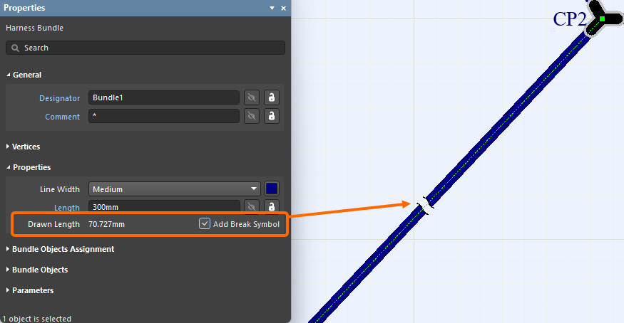
添加断点
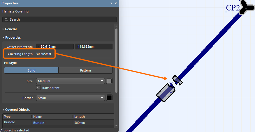
断点用于指示该束为非按比例(NTS),可放置在线束束上。束会在其最长线段的中间显示断裂符号,如下方第一张图所示,同时属性中会显示 Drawn Length。要放置断点,请在束属性的 Properties 区域中启用 Add Break Symbol 选项。覆盖带有断点的线束束的线束包覆层也会在相同位置显示断裂。如果线束包覆层在束断点处结束,则包覆层会绘制得略长一些,如第二张图所示。
 )。了解更多关于使用 MCAD CoDesigner 进行


Jumper Wires
跳线可以显示在布局图中。当线束项目的接线图包含一根连接同一线束连接器内腔位的导线时,在设计空间中选中线束束组后,该导线会在 Properties 面板中显示为线束束组的一个对象,并对应到项目布局图上的该线束连接器。


线束束组覆套
可以在线束束组上放置线束覆套对象(Place » Harness Covering)。 覆套长度可在设计空间中放置时或放置后以图形方式修改。
选择线束覆套放置命令后,当光标悬停在线束束组上时,设计空间中会出现一个橙色圆点,表示可放置线束覆套(灰色圆点表示在该具体位置无法放置线束覆套)。在希望覆套开始的位置单击,然后沿束组移动光标到希望覆套结束的位置,再次单击。线束覆套可以相互重叠,如下方视频所示。
当在设计空间中选中线束覆套时,可在 Properties 面板中配置已放置线束覆套的属性。

选中线束覆套时的 Properties 面板
你可以在 Properties 面板中使用 Size 下拉菜单,基于其所覆盖束组的尺寸(束组的 Line Style)来定义线束覆套对象的大小。滚动浏览下方图片,查看不同束组尺寸下的不同覆套尺寸示例。


线束覆套也可配置为 带编织纹理。在 Properties 面板的 Fill Style 区域中,选择 Pattern,然后使用 Pattern 下拉菜单选择所需的编织颜色(黑色、黄色或红色)。


覆套的起点取其路径中最靠左、最靠上的点,并且该路径仅包含覆套所覆盖的束组。
你可以将线束覆套应用/延伸到一个接合点(布局图中两个或多个束组汇合的连接点)上。这样就无需在包含多个连接器的某一段中,在各接合点之间分别放置独立的线束覆套。

添加布局标签
可在布局图中放置实体标签(Place » Layout Label)。

当在设计空间中选中布局标签时,可在 Properties 面板中配置已放置布局标签的属性(其标号、文本、可视化表现等)。

选中布局标签时的 Properties 面板
在 Text 字段中定义标签文本时,使用 Ctrl+Enter 或 Shift+Enter 来添加新的一行文本。启用 Show only first line 可在设计空间中仅显示 Text 字段的第一行。还可以使用 Alignment 控件按需对齐布局标签文本。


从库更新布局图对象
以下对象可从其源 Workspace 库更新:
-
线束元件
-
与线束元件关联的部件
-
与连接点关联的部件
-
线束覆套
-
布局标签
当选中某个对象时,可在 Properties 面板中找到与之链接的 Workspace 元件信息(例如,线束元件关联部件的 Associated Parts 选项卡,或布局标签的 General 区域)。
如果存在更新版本的 Workspace 元件可用,修订状态条目会用文本 Out of date 反映这一点。在单个对象层级,可通过单击 ![]() 按钮将链接更新到 Workspace 元件的最新修订版。
按钮将链接更新到 Workspace 元件的最新修订版。

指示线束元件修订版已过期的示例
Update from Libraries 功能(Tools » Update from Libraries)也可用于更新与上述对象列表关联的过期元件。 注意:要使某个对象能通过 Update from Libraries 功能纳入更新,分配给该对象的元件必须包含指向原理图符号的链接。

标注线束布局图对象
使用 Tools » Annotation 菜单中的命令,可对线束布局图文档中的以下对象进行标注:
-
线束元件
-
连接点
-
线束束组
-
线束覆套
-
布局标签

在线束布局图文档中标注对象,类似于在 PCB 设计项目的原理图文档(*.SchDoc)中标注元件。使用以下链接了解线束布局图文档可用的标注命令:
接线图与布局图之间的交叉探测
支持在线束项目的接线图与布局图之间进行交叉探测。可在 Tools 主菜单以及设计空间的右键菜单中访问 Cross Probe 命令。
交叉探测可在以下对象之间执行:
-
接线图与布局图中的元件之间。
-
从接线图中的一根导线定位到布局图中该导线所经过的束组。
-
从布局图中的一个束组定位到接线图中穿过该束组的导线。
|
从线束图中的某个元件交叉探测到布局图中对应的元件。 从布局图中的某个元件交叉探测到线束图中对应的元件。 从线束图中的某根导线交叉探测到布局图中对应的线束束组。 从布局图中的某个线束束组交叉探测到线束图中对应的导线。 |


 AI 翻译
AI 翻译