
Defining the Wiring Diagram
The individual wired connections within the harness are specified in the harness wiring diagram (*.WirDoc). Add this document to the harness project from the Projects panel by right-clicking on the project entry and then selecting Add New to Project » Harness Wiring Diagram from the context menu (or use the File » New » Harness Wiring Diagram command from the main menus).
Setting Up a Harness Wiring Diagram Document
Options of a harness wiring diagram document can be configured in the Properties panel when no object is selected in the document's design space. The main settings are:
-
In the General region of the panel's General tab – select the measurement units that apply to the document and its graphic elements and set the grids to enable easier placement. Altium Designer offers three grid types: visible grid for navigation, snap grid for placement, and snap distance for aiding the creation of connections.
-
In the Page Options region of the panel's General tab – configure document sheet size and title block or select from available harness wiring diagram templates.


The General and Parameters tabs of the Properties panel when no object is selected in the harness wiring diagram document
Synchronizing Multi-board and Harness Projects
When the harness project is part of a multi-board design project, the harness wiring diagram can be synchronized from the multi-board schematic document (*.MbsDoc) data. To do so, select the Design » Import Changes From <Multi-board Project> command from the main menus.
To learn more about adding a harness design project to a multi-board project, refer to the Harness Design page.
If the multi-board schematic document contains more than one harness connection definition, the Select Harness Definition dialog will open. Specify the definition that relates to the current harness project.

The Select Harness Definition dialog
The Engineering Change Order dialog will then open showing the harness connector components and harness nets that were defined in the multi-board schematic, which will form the basis for the harness wiring diagram.

Use the Engineering Change Order dialog to import data from the multi-board project.
After executing the changes (![]() ), the data from the multi-board schematic document is imported into the harness wiring diagram. The connector components, each represented by its schematic symbol, will appear in the harness wiring diagram document, initially in arbitrary positions.
), the data from the multi-board schematic document is imported into the harness wiring diagram. The connector components, each represented by its schematic symbol, will appear in the harness wiring diagram document, initially in arbitrary positions.

An example of a harness wiring diagram right after import.
Netlines will be shown between the pins to represent the logical connections defined in the multi-board schematic. Note that at this stage, there are no physical wires in the design.
Working with Components
As well as synchronizing from the multi-board schematic document, components can also be placed manually into the harness wiring diagram. This allows components to be placed in a standalone harness project (that is not part of a multi-board project), but also allows additional components to be placed in a harness wiring diagram that is part of a multi-board project.
Use the Components panel to place the symbols of the required components. The component placement process is similar to that in the Schematic editor – refer to the Searching for & Placing Components page to learn more. Note that there will be no net lines for manually added components, as there is no higher-level logical design to drive them.
 ).
).To move a placed component (or a component being placed from the Components panel) to the desired position, click and hold the left mouse button on it and move the mouse. During dragging, use the Spacebar to rotate the components by 90 degrees and the X and Y keys to flip them horizontally and vertically, respectively.

The harness wiring diagram after moving the components
Properties of a placed component can be configured in the Properties panel when the component is selected in the design space. The Properties panel for a component includes the following tabs:
-
General – general properties of the component, such as designator and comment, location, parameters, etc.
-
Pins – the list of component pins.
-
Cavities – allows socket cavities to be assigned to the component (learn more).
-
Associated Parts – allows additional parts, such as heatshrink, to be assigned to the component.

Tabs of the Properties panel when a component is selected
Assigning Socket Cavities
Socket cavities and their type can be assigned to a harness component. Select a component in the design space to add a cavity and type. Select a pin on the Properties panel's Cavities tab, then click the ![]() button. Select the desired type from the drop-down. The following cavity types are supported:
button. Select the desired type from the drop-down. The following cavity types are supported:
-
Crimp – used to provide an electrical connection by compressing a contact barrel around a conductor.
-
Seal – used to provide environmental protection by sealing the wire entry point.
-
Plug – used to fill an open (unused) connector cavity to maintain the integrity of the environmental seal.
-
Other – used to specify other/additional parts or materials, e.g., solder.
In the Select Connector dialog that opens, browse to and select the desired component. The specific type and pertinent information will be added to the pin on the tab, as shown in the images below, for adding a crimp to pin 1.

For a crimp, seal, or plug, only one cavity of a particular type can be added to a pin. Once a cavity of a particular type has been added, the entry is unavailable (grayed out) in the drop-down. Any number of cavities of the Other type can be added to a pin.
Pins with assigned crimps are denoted by the ![]() symbol in the design space, as shown in the image below.
symbol in the design space, as shown in the image below.

The grid region of the Cavities tab supports multi-selection and copy/paste/delete operations for selected entries.
-
Multiple pin entries can be selected using
Click, Hold&Drag,Ctrl+Click,Shift+Click, andCtrl+Ashortcuts. -
When multiple pin entries are selected, click
 to add a cavity to all selected pins or click
  or press
 Deleteto remove added cavities from selected pins. -
To change a pin's cavity, select its entry, then click
 to open the Select Connector dialog to select the new cavity.
-
Select one or more pin entries and use
Ctrl+X/Ctrl+Cshortcuts to cut/copy selected entries, then use theCtrl+Vshortcut to paste cut/copied content at the currently selected entry.
Creating Connectivity in the Harness Wiring Diagram
Physical wires are placed in the harness wiring diagram document by selecting the Place » Harness Wire command from the main menus (shortcut: Shift+W).
After selecting the command, click a pin of a connector (a red cross appears at the cursor when it is over a pin's hotspot) to place the start point of the harness wire. Position the cursor and click to anchor a series of vertex points that define the shape of the harness wire. After placing the final vertex point at another pin's hotspot, right-click to complete placement.
When placing a harness wire, press Shift+Spacebar to cycle through placement modes. The mode specifies how corners are created when placing wires and the angles at which wires can be placed. While in 90 Degree or 45 Degree mode (true orthogonal modes), press Spacebar to cycle between the start and end sub-modes. The current mode and sub-mode are shown in the Status Bar.
When placing a harness wire, the netlines track/refresh 'live,' showing you where to wire in real-time, as demonstrated in the video below. Once a connection is completed, its netline disappears from the document.
Demonstration of the live trace feature
When placed and selected, a harness wire’s vertices can be dragged to change the angle between two adjacent sections ( ).
).
Select a harness wire in the design space to change it in the Properties panel. From the panel, you can rename the selected harness wire, change its width and color, and add parameters that can be shown or hidden in the design space.

The Properties panel when a harness wire is selected


Adding Splices and Taps
In design situations where a new wire needs to be connected to an already placed wire, a splice (Place » Splice) or tap (Place » Tap) object must be placed first.
-
Splice – the original wire is split into two separate wires by the splice.
Another wire needs to be connected to the selected wire (W4).
A splice placed on the wire. Note that the splice splits the original wire into two in the splice location.
Another wire has been connected to the splice.
-
Tap – the original wire remains unbroken.
Another wire needs to be connected to the selected wire (W4).
A tap placed on the wire. Note that the tap does not split the original wire.
Another wire has been connected to the tap.


 ).
).

Properties of a placed splice or tap (its location and visual representation) can be configured in the Properties panel when the object is selected in the design space.

The Properties panel when a splice/tap is selected
The Associated Parts region of the Properties panel allows components to be assigned to the selected splice/tap, and this component will be reflected in the project's BOM.
Adding Cables
To define one or more wires as added to a cable, you can place a cable object on the harness wiring diagram (Place » Harness Cable).

Place a cable to define one or more wires as added to a cable.
When a cable object is selected, the wires covered by this cable are highlighted in the design space in neon green ( ).
).
Properties of a placed cable object (its location, visual representation, and parameters) can be configured in the Properties panel when the object is selected in the design space.

The Properties panel when a cable is selected
 ).
).Wire Shielding and Twisting
A shield (with or without a connection, such as a drain wire connection) can be attached to a group of wires by placing either a shield (Place » Shield) or a shield with connection (Place » Shield with Connection) object.
In the example shown below, wires W1, W2, and W3 are shielded by a shield without a connection (SH1), and wires W4, W8, and W9 are shielded by a shield with connection (SH2). Wire W10 is placed to connect SH2 to a component pin.

Placed a shield or shield with connection object to denote wires as shielded.
When a shield or shield with connection object is selected, the covered wires are highlighted in neon green in the design space ( ).
).
Properties of a placed shield or shield with connection object (location and visual representation) can be configured in the Properties panel when the object is selected in the design space. The Shield Objects region of the panel lists wires covered by the selected object.

The Properties panel when a shield is selected
 ).
).Wires can be denoted as twisted together by placing a twist (Place » Twist). A twist can be placed across two or more wires.
In the example shown below, wires W1 and W2 are denoted as twisted together with twist Tw1.

Place a twist object to denote wires as twisted together.
When a twist is selected, the covered wires are highlighted in neon green in the design space ( ).
).
The properties of a placed twist (its location and visual representation) can be configured in the Properties panel when the object is selected in the design space. The Twist Objects region of the panel lists wires covered by the selected twist.

The Properties panel when a twist is selected
 ).
).Unconnected Wires
Unconnected wire ends are indicated with a solid square.

An indicated unconnected wire
A wire end should not be left unconnected. If the design requires an unconnected wire end, a 'no connect' object should be placed at the end (Place » No Connect).

Place a 'no connect' object at the end of a wire that should remain unconnected.
Properties of a placed 'no connect' object (its location and visual representation) can be configured in the Properties panel when the object is selected in the design space.

The Properties panel when a 'no connect' object is selected
Working with Multiple Sheets
A full harness wiring diagram can be defined over multiple sheets (in a 'flat' design fashion, where all sheets exist on the same level), each represented by its own *.WirDoc document. The connectivity is created directly from any sheet to any other sheet using wire break objects (Place » Wire Break) with the same wire designator.

After selecting the wire break placement command, position the object so that its electrical hotspot (the end held by the cursor) touches the wire to which you want to connect, then click or press Enter to effect placement. A placed wire break inherits properties (designator and color) of the wire to which it is connected.

Select a wire break in the design space to change it in the Properties panel. From the panel, you can define the designator of the wire to which it is connected and its style: direction (Left or Right) and color.

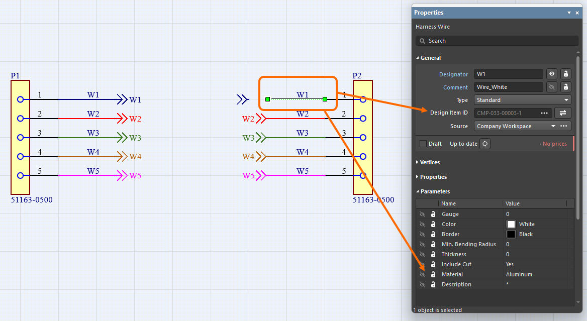
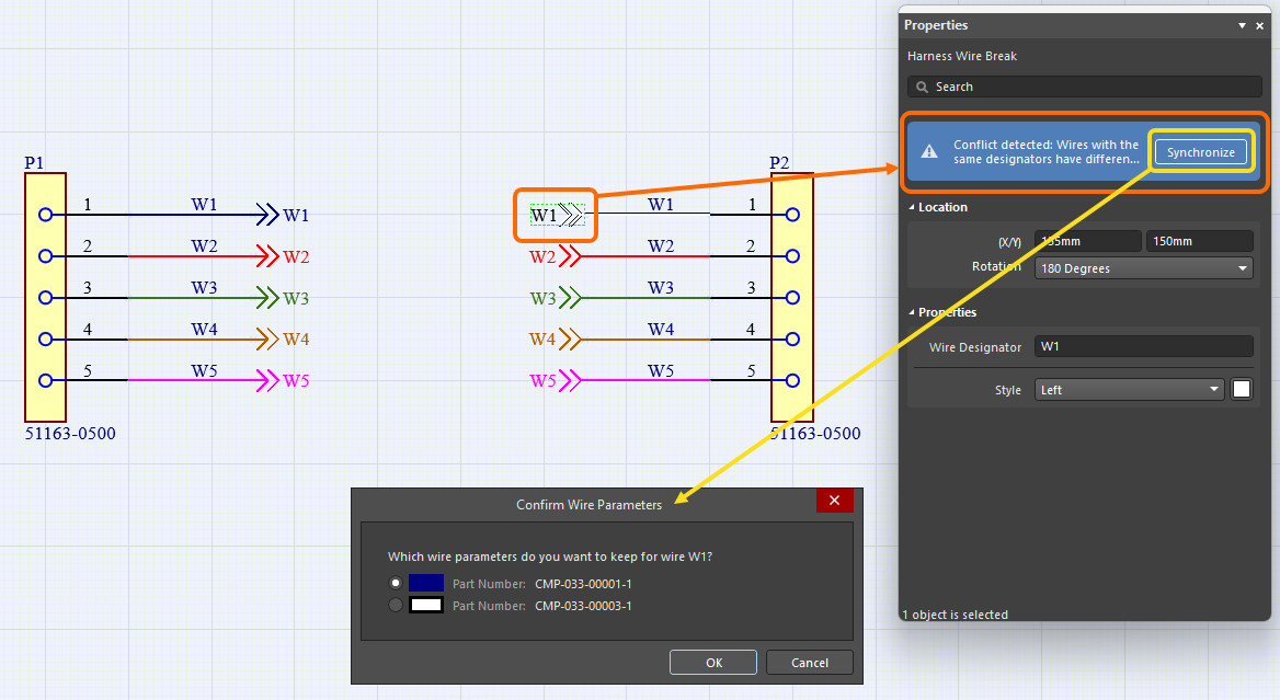
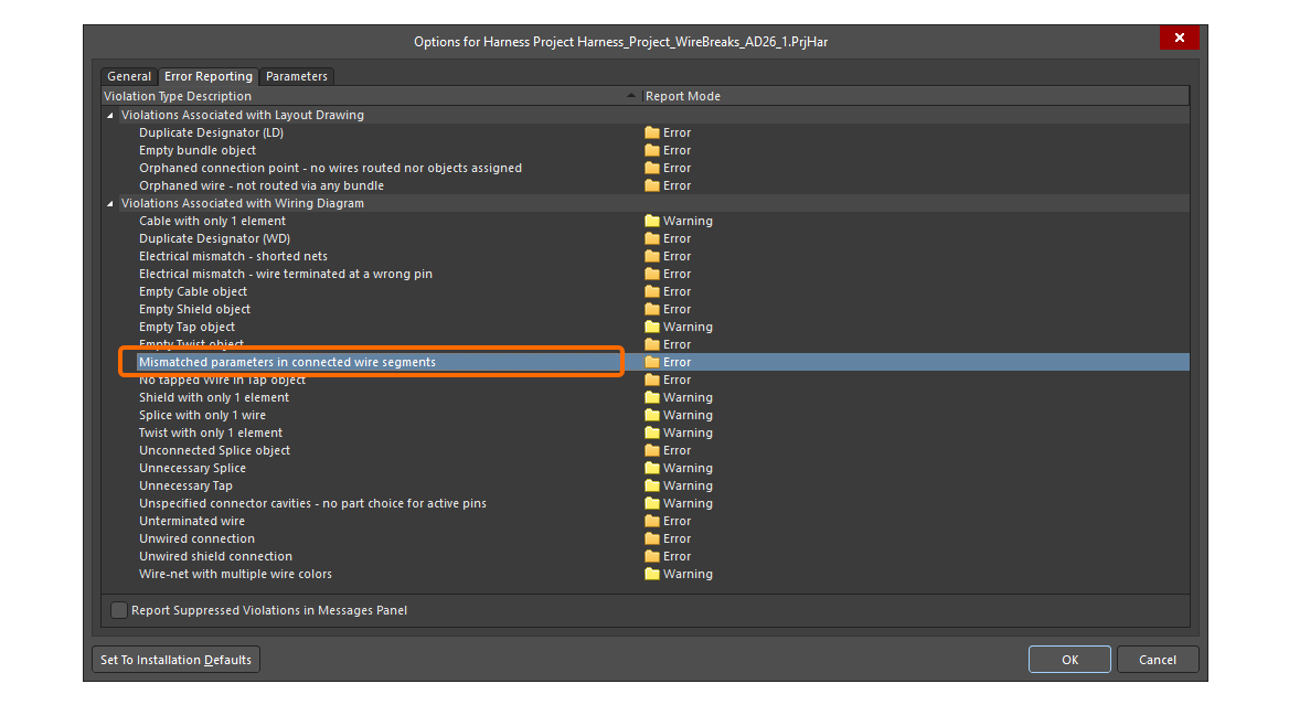
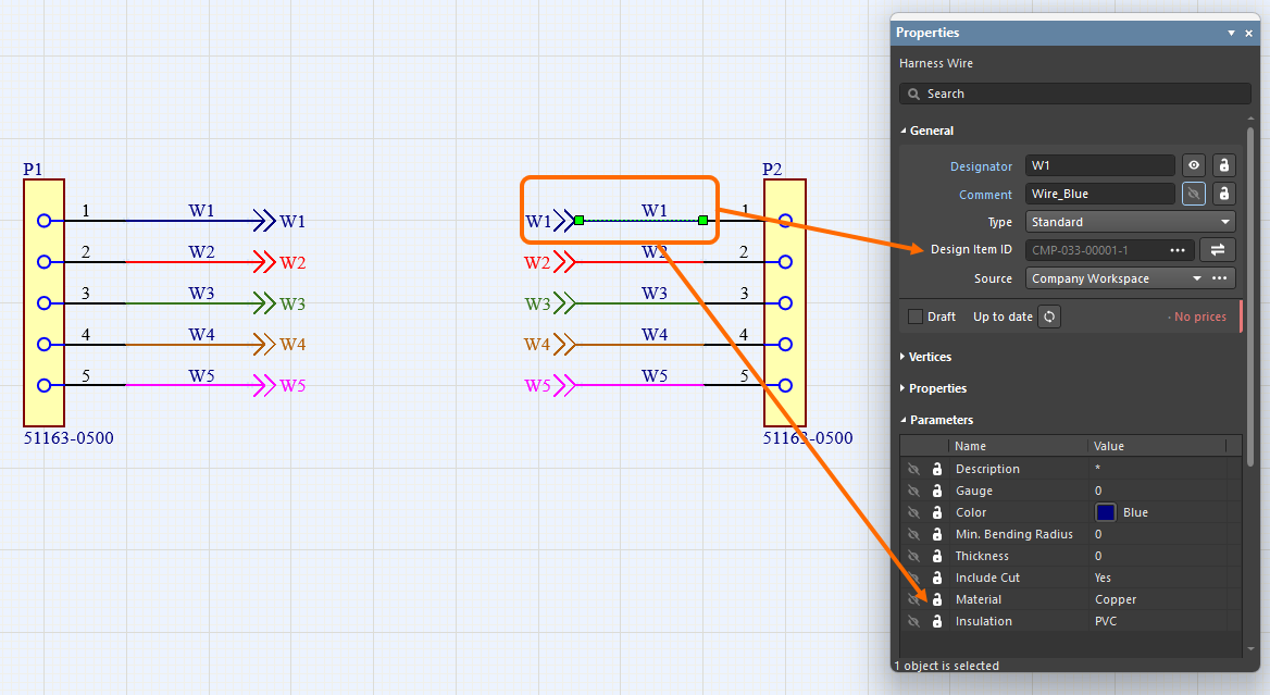
Synchronization of Wires
Harness wires connected with a wire break are recognized even if they have different Design Item IDs. In addition, all wire segments with the same designator connected by the same wire break are compared (for part number, comment, color, and all parameters). If any differences are found, the Mismatched parameters in connected wire segments violation is reported. A warning also appears in the Properties panel of the wire and wire break signifying that a conflict has been detected between the parameters. Click Synchronize within the warning to open the Conflict Wire Parameters dialog, which gives you the choice of which parameters to use for the wire segment.
 ).
).Placing a Harness Wiring Component
When connected to your Workspace, you can create components with predefined structure and properties as required in the connected Workspace and then reuse those components in your harness designs, placing them directly in harness wiring diagram documents.
Refer to the Creating a Harness Wiring Component page to learn more.
These components (each with a defined harness wiring model assigned) are accessed from the Components panel. When the required harness wiring diagram document is the active document in the design space, place a component by right-clicking its entry in the panel and selecting the Place <ComponentName> command from the context menu. The behavior of placing a component differs depending on whether the component includes a single wire object or a cable structure (multiple wires and/or additional objects: cables, shields, etc.).
-
Single wire – when placing a component that includes a single wire object, you will enter harness wire placement mode. The wire being placed will inherit the properties defined during component creation. Refer to the Creating Connectivity in the Harness Wiring Diagram section above to learn more about harness wire placement.
-
Cable structure – when selecting the placement command for a component that includes a cable structure, that cable structure will appear attached to the cursor exactly as it was defined during component creation. Click in the desired place of the harness wiring diagram document to place the component. You can then individually edit objects of the component, for example, to attach wires composing the cable to the pins of harness connectors.
Updating Wiring Diagram from Libraries
The following objects can be updated from their source Workspace library:
-
Harness components
-
Cavities of harness components
-
Parts associated with harness components
-
Wires
When an object is selected, the information about the linked Workspace component can be found in the Properties panel (e.g., the Associated Parts tab for a harness component's associated parts).
If there is a later revision of the Workspace component available, the entry for the revision status will reflect this using the text Out of date. At the individual object level, the link can be updated to the latest revision of the Workspace component by clicking the ![]() button.
button.

An example of indicating an out-of-date harness component revision
The Update from Libraries feature (Tools » Update from Libraries) can also be used to update out-of-date components linked to the objects listed above. Note that for an object be included into the update using the Update from Libraries feature, a component assigned to the object must include a link to a schematic symbol.

Annotating Harness Wiring Diagram Objects
Use the commands in the Tools » Annotation menu to annotate the following objects in the harness wiring diagram document:
-
Harness components
-
Wires
-
Splices and taps
-
Cables
-
Shields and shields with connection
-
Twists
-
'No connect' objects

Annotating objects in a harness wiring diagram document is similar to annotating components in a schematic document (*.SchDoc) of a PCB design project. Use the following links to learn more about annotation commands available for a harness wiring diagram document: