可以为您的 PCB 设计准备并生成多种装配文件格式,包括:
-
装配图
-
贴装坐标文件
-
装配测试点报告
-
键合线表格报告
可通过文件的 [Add New Assembly Output] 区域中的 Assembly Outputs 控件菜单,或通过主菜单的 Edit » Add Assembly Outputs 子菜单,将装配输出添加到当前活动的 Output Job 文件中。

虽然 OutputJob 文件便于为您的设计高效准备输出,并通过高完整性的项目发布流程进行后续生成,但也可以在 PCB 编辑器中使用 File » Assembly Outputs 子菜单中的命令,直接为当前活动的 PCB 设计生成装配输出。
准备装配图
Assembly Drawings 输出是一种基于打印的输出,具有针对页面及其图层的预定义设置。访问 Print 对话框以查看并调整该输出的配置。
更多信息请参阅 Configuring PCB Printouts 页面。
准备贴装坐标文件
Generates pick and place 输出生成器会生成一份报告,详细列出板上每个元件的位置、旋转角度以及所在板面(正/反面)。报告可生成 CSV 或文本格式。所有元件类型为 Standard 的元件都会包含在报告中。类型设置为其他值(例如 Graphical)的元件不会包含在内。
所需报告在 Pick and Place Setup 对话框中进行配置。

Pick and Place Setup 对话框
Options and Controls of the Pick and Place Setup Dialog
-
All Columns - 参数列表,您可以从中选择要包含在输出文件中的参数。启用您希望包含在输出中的参数的 Show 列。位置信息以三种方式表示,对应于在源 PCB 库中指定元件封装参考点的三种方法:
-
Center X、Center Y - 元件中心点坐标(计算方式为最外侧焊盘位置之间的中点)
-
Ref X、 Ref Y - 元件用户自定义参考点坐标(封装原点)
-
Pad X、 Pad Y - 元件 1 号焊盘的坐标。
-
Grid region - 此区域为将包含在输出文件中的信息预览。
-
Output Settings
-
Units - 使用此区域指定元件位置坐标采用 Imperial 或 Metric 计量单位。
-
Show Units - 启用以显示单位。
-
Separator - 从下拉列表中选择所需的单位分隔符。
-
Formats - 选择要以何种格式(CSV 和/或 Text)生成输出。
-
Exclude Filter Parameters - 启用以排除用于筛选的参数(更多信息请参阅下方 Tips 部分)。
-
Include Variation Component - 启用以包含变体。
-
Distinguish different footprints with the same name - 启用后,如果同名封装中有一个被修改,则输出中只会将该被修改的封装标记为更改;未启用时,所有同名封装都会在输出中显示为已修改。
-
Include Standard (No BOM) Items - 启用以包含 standard components,从而支持基准点(fiducials)。
-
Y-Flip Bottom Side Components - 启用此选项可反转底层元件的 Ref-Y 和 Pad-Y 数值的符号。
筛选
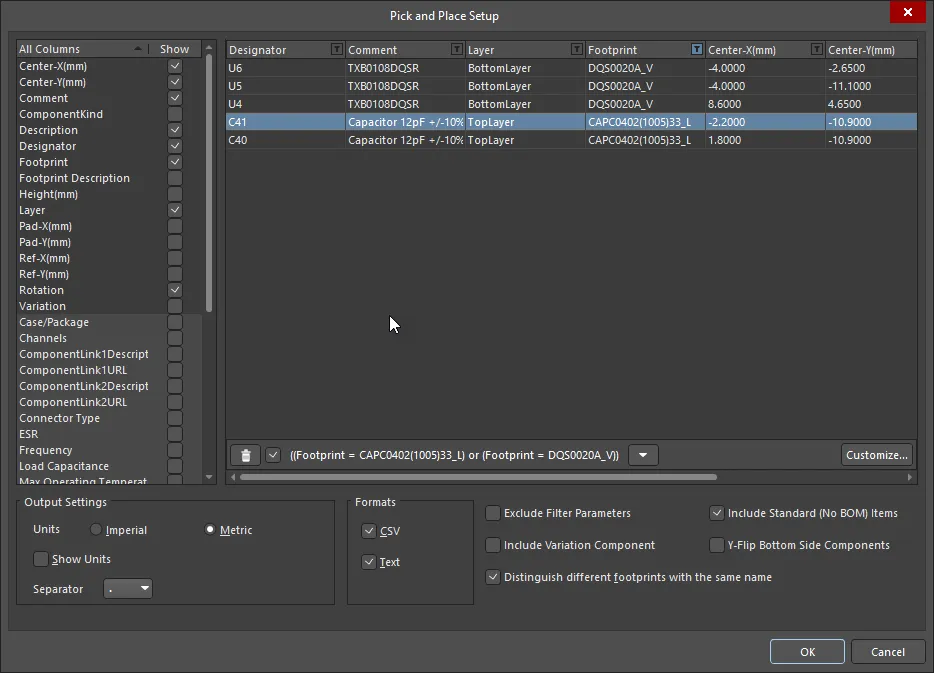
应用筛选后,Pick and Place Setup 对话框将如上所示。该变体中的附加控件包括:
-
 - 单击以删除右侧显示的筛选。可使用右侧复选框启用/禁用筛选,而无需将其完全删除。
-
Down arrow - 单击以访问之前筛选的列表。选择所需筛选以筛选当前网格。
-
Customize - 单击以打开 Filter builder 对话框,创建更高级、更复杂的筛选器。
要从报告中排除特定器件,对话框提供了应用自定义筛选的能力。要应用筛选,请单击列标题中的筛选图标(

)。注意,随后出现的菜单会列出所有单独的行条目,便于快速选择性筛选。单击
(Custom…) 条目以访问
Custom Filter 对话框。使用该对话框可根据为该列定义的筛选条件,指定在 BOM 中显示哪些数据行。应用后,筛选图标会变为蓝色(

),表示该列已启用自定义筛选。根据需要对其他数据列应用自定义筛选——当前应用的完整筛选条件会显示在数据区域左下角。通过启用
Exclude Filter Parameters 选项,还可以将用于筛选的列从生成的贴装坐标文件中排除。
准备装配测试点报告
装配测试点报告生成器会生成一份报告(txt 和/或 csv 和/或 IPC-D-356A 格式),包含所有设置为装配测试点的焊盘与过孔。
关于在 PCB 设计中分配测试点的更多信息,请参阅 Assigning Testpoints on the Board 页面。
测试点报告支持嵌入式拼板(embedded board arrays)。当从包含多个嵌入式拼板的 PCB 文档导出时,会生成多个 IPC-D-356A 网表文件。
装配测试点报告的输出选项通过 Assembly Testpoint Setup 对话框进行配置。

AssemblyTestpoint Setup 对话框

 AI 翻译
AI 翻译