Capturing Your Design Idea as a Schematic
Schematic capture is the process of creating a logical representation of an electronic circuit. When you capture a schematic, you are connecting a collection of component symbols together in a unique way, creating your unique electronic product.
Setting Up the Schematic Editor
The Schematic category of the Preferences dialog (accessed by clicking the  icon at the top-right of the design space) provides access to pages of preferences affecting the behavior of the schematic editor. Access these preferences at any moment to configure settings as required.

Use the Schematic category of Altium Designer's Preferences to set up the schematic editor.
Setting Up a Schematic Document
To start capturing the schematic for your PCB design, add a new schematic document to the PCB project. To do this, right-click the project's entry in the Projects panel and select Add New to Project » Schematic command from the context menu. The default schematic document will appear in the design space.

A newly created schematic document will be the active document in the design space.
Options for a schematic document are configured in the Properties panel when no object is selected in the design space. The main options are configured on the General tab of the panel:
- Units (the General region) – select the preferred measurement units (mm or mils) for the document.
-
Grid and snap settings (the General region) – set the required values for easier navigation and object placement.
- Page options (the Page Options region) – configure the Formatting and Size, as well as Margins and Zones for the document. You can select an available Template, choose a Standard sheet size or define a Custom size.

Configure options of the schematic document in the Properties panel.
Searching for and Placing Components
Components are essential elements of each electronic design. When you place a component onto your schematic, you place its schematic symbol linked to other models (such as a PCB footprint and simulation model) and equipped with the list of parameters.
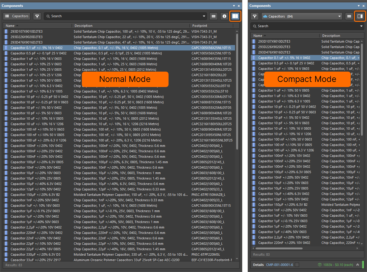
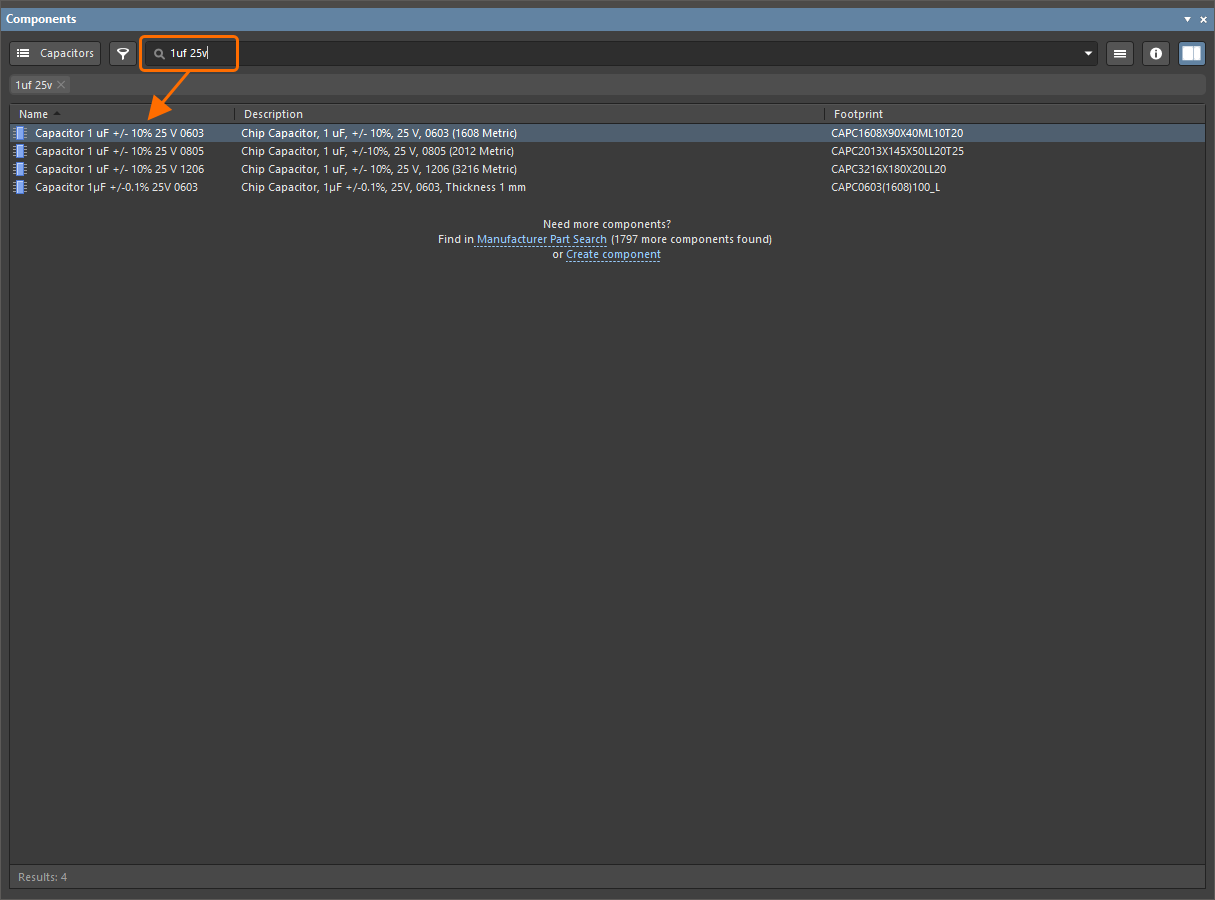
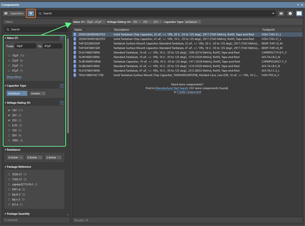
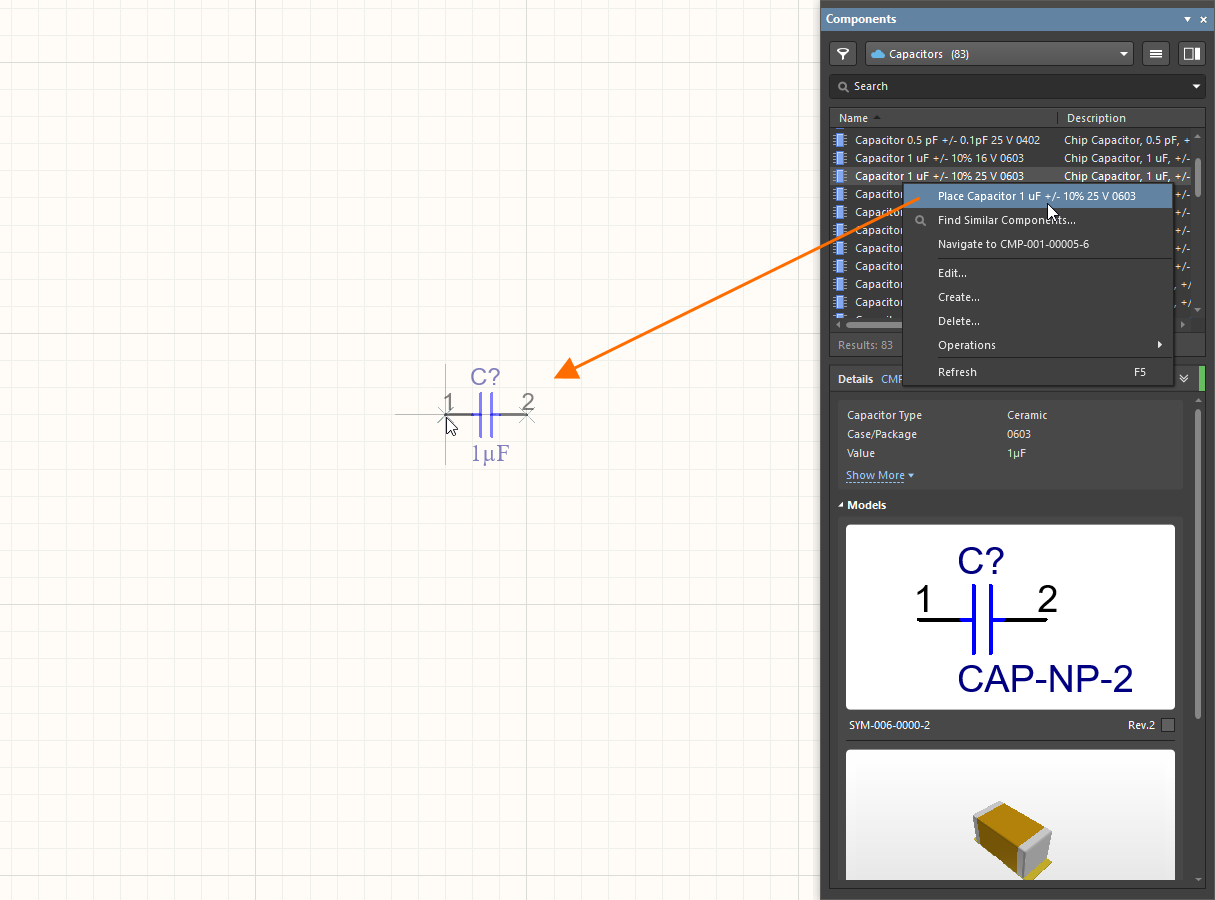
The Components panel provides access to available component libraries from where you can search and place required components. The main features of the panel are shown and described below.
|
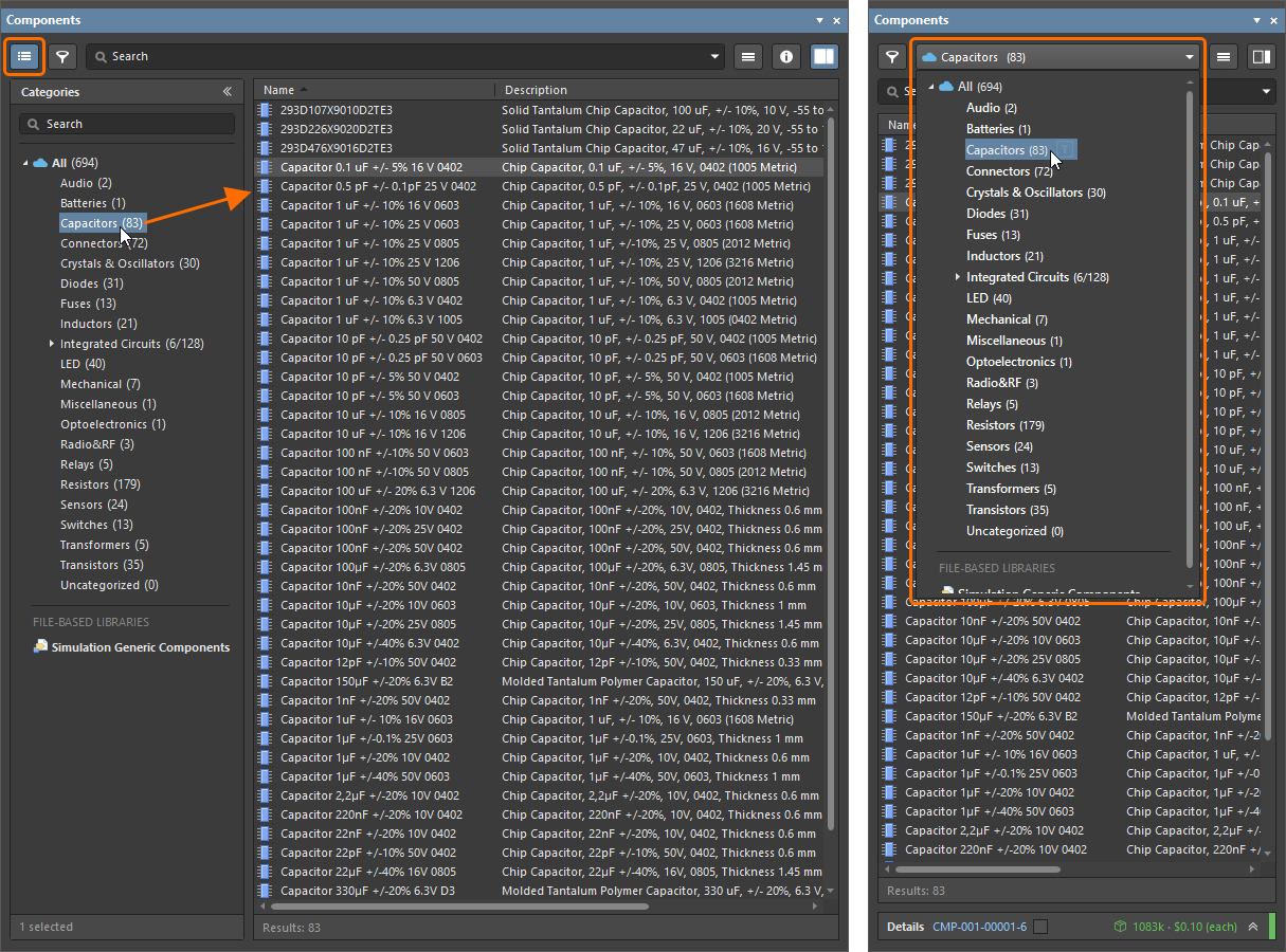
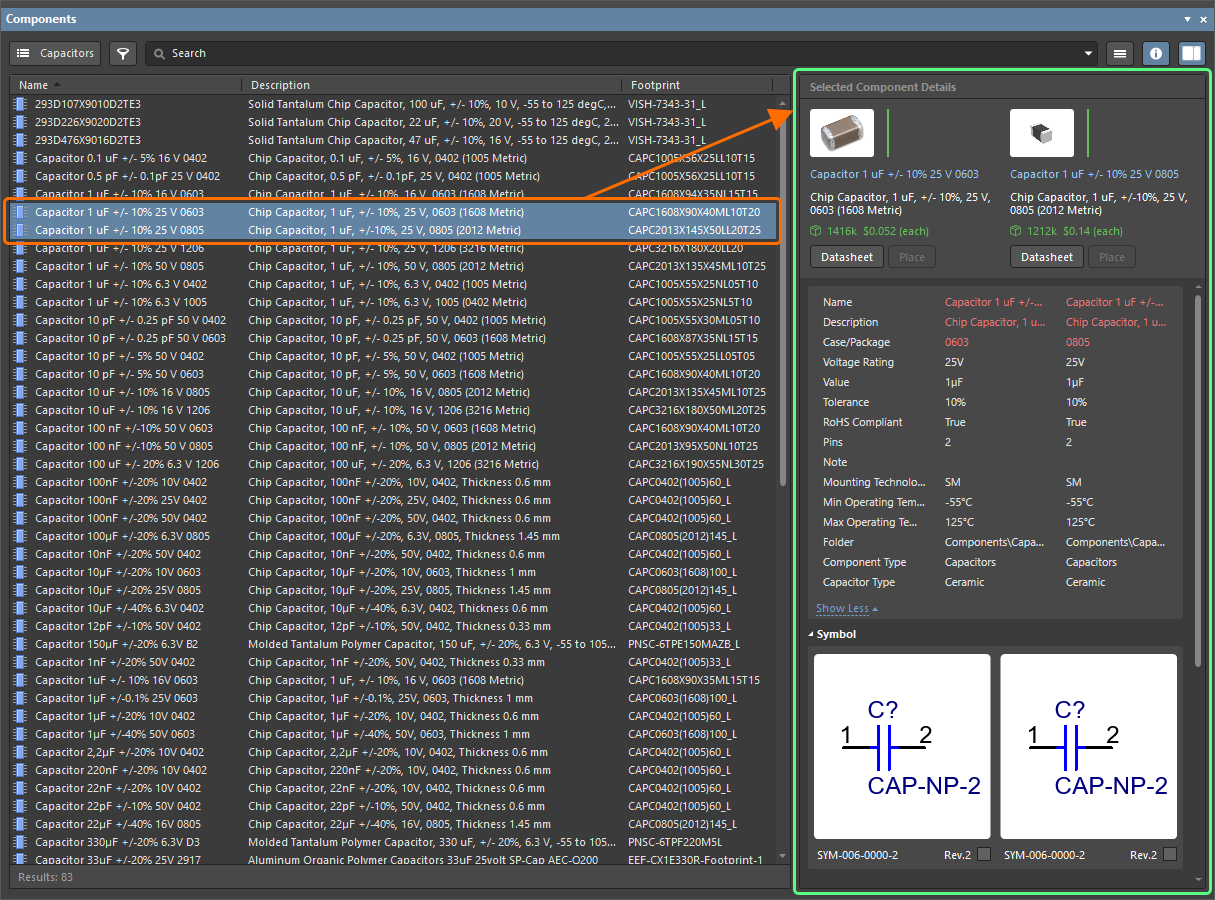
The Components panel can operate in two modes: normal and compact. Use the Use the Categories list to choose a specific component category you want to browse. Access the list by clicking the Use the Search field at the top of the panel to search components in the chosen category by their parameters. For your Workspace library components, use Filters accessed by clicking the Click the Ctrl+Click two components in the list to compare their details, with differences highlighted in red. Right-click a component in the list and select Place to place the component onto the schematic sheet. |
 /
/  button at the top-right of the panel to switch between these modes.
 button at the top-left of panel (in its normal mode) or using the drop-down at the top of the panel (in its compact mode).
 button at the top-left of panel to narrow the list of components by the required parameter values.
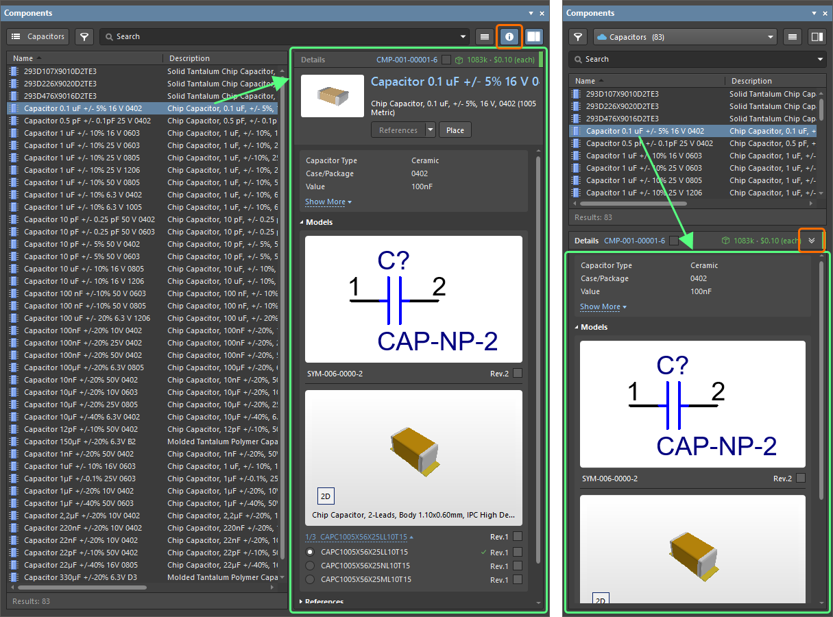
 button at the top-right of the panel to display the Component Details pane (normal mode) or click the
  at the bottom of the panel (compact mode) to browse detailed information for a component selected in the list.
You can also search for real-world manufactured parts using the Manufacturer Part Search panel, which uses the basic search engine functionality and view applied in the Components panel. A selected manufacturer part can be used as a basis for a new component in your connected Workspace, or its parameters and datasheets can be added to a placed component.

The Manufacturer Part Search panel
The  icon in a part entry means that there are models (schematic symbols, PCB footprints, simulation models) assigned to this component. When creating a new component based on this manufacturer part, models from it will also be acquired. Alternatively, you can download this part locally or place it directly onto your schematic.
Wiring the Circuit
Components are connected by wiring the pins together. This can be done by placing wires between pins:
- Select the Place » Wire command from the main menus.
- Position the cursor over a component pin's hotspot – a red connection marker (red cross) will appear at the cursor location. This indicates that the cursor is over a valid electrical connection point on the component.
- Click to anchor the starting point for the wire.
-
Position the cursor, then click in the design space to anchor a series of vertex points that define the shape of the wire.
- Position the cursor over the hotspot of the target component pin until you see the cursor change to a red connection marker.
- Click to connect the wire to the pin. The cursor will release from that wire.
- Place another wire or right-click to exit wire placement mode.
To make it easy to identify important nets in the design, you can add net labels to assign names.
- Select the Place » Net Label command from the main menus.
- Press Tab to edit the properties of the net label in the Properties panel before placing it.
- In the Net Name field of the Properties panel, type in the required name.
- Click the
 button in the design space to return to placement mode.
 - Position the cursor over a wire to which you want to assign the net label – a red connection marker (red cross) will appear at the cursor location.
- Click to place the net label.
- Place another net label or right-click to exit placement mode.
Creating a Multi-sheet Design
To keep the schematic design manageable and readable, it can be spread over multiple sheets. As soon as you add a second schematic sheet to your project, the design is considered a multi-sheet design.
There are two approaches to organizing a design over multiple sheets: flat or hierarchical.
-
Flat design – the connectivity between nets that span sheets is directly from one sheet to any other sheet. All sheets exist on the same level.

A diagram demonstrating connectivity in a flat design. Use of the top-level sheet is optional. -
Hierarchical design – the design is arranged in a tree-like, or hierarchical structure, using a sheet symbol to represent each lower-level sheet, and the sheet entries (Place » Sheet Entry) in it represent, or connect to, the ports (Place » Port) on the sheet below. The connectivity is through the sheet entries in those sheet symbols – not directly from the ports on one sheet to the ports on another sheet.

A diagram demonstrating connectivity in a hierarchical design.
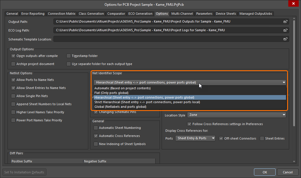
To work out how to establish connectivity between the schematic sheets, Altium Designer uses the current setting of the Net Identifier Scope option configured on the Options tab of the Project Options dialog accessed by right-clicking the project entry in the Projects panel and selecting Project Options.
While you can place sheet symbols and sheet entries and define their properties manually, the schematic editor includes commands that allow you to build a hierarchical structure quickly and efficiently:
-
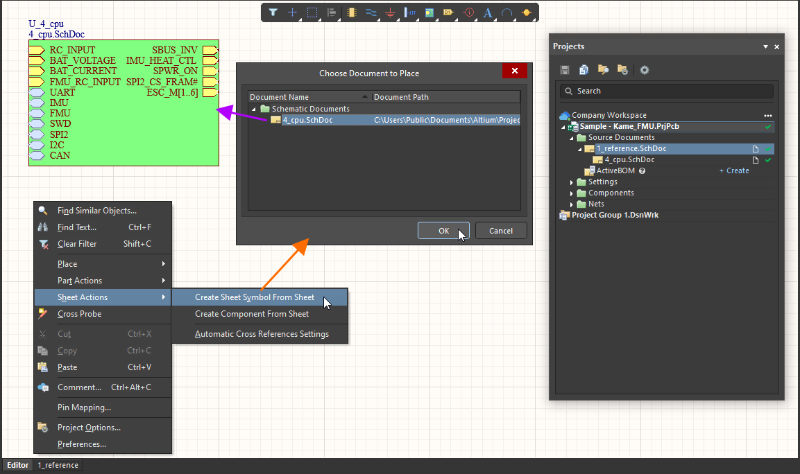
Design » Create Sheet Symbol From Sheet – use this command to create a symbol from the nominated schematic sheet. To use this command, first switch to the sheet that will hold the new sheet symbol, then launch the command. The Choose Document to Place dialog will open – use this to choose the target schematic document that is to be referenced by the newly-created sheet symbol. The sheet symbol will include a sheet entry to match each port it finds.
-
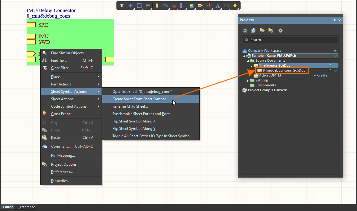
Design » Create Sheet From Sheet Symbol – use this command to create a new schematic sheet below the nominated sheet symbol. The matching ports to the sheet entries on the symbol will be located in the bottom left corner of the new document.
Annotating the Design
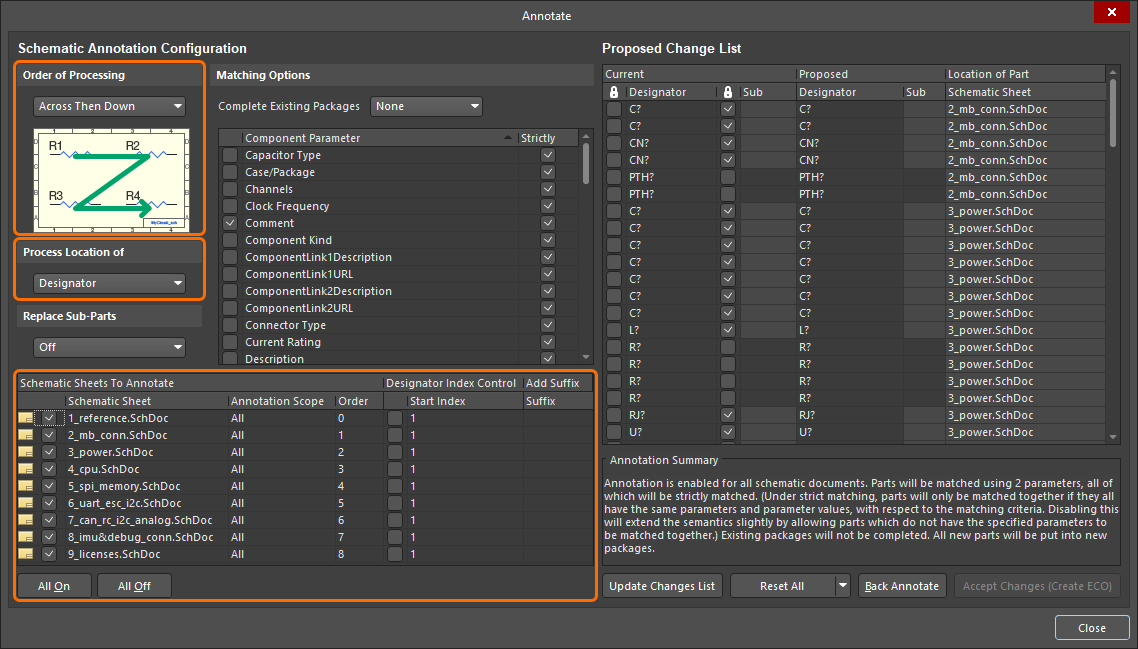
Design annotation is the process of ensuring that each component in the design can be individually identified by means of a unique designator. Schematic annotation is configured using the Annotate dialog. The dialog provides controls to systematically assign designators to all or selected parts in selected project sheets and ensures that designators are unique and ordered based on their position.
The basic process of schematic annotation is following:
- Access the Annotate dialog by selecting the Tools » Annotation » Annotate Schematics command from the main menus.
- In the Schematic Annotation Configuration region of the dialog (the left-hand side of the dialog), configure the annotation scheme and the scope of annotation. The main settings are the Order of Processing option, the Process Location of option, and the list of Schematic Sheets to Annotate.
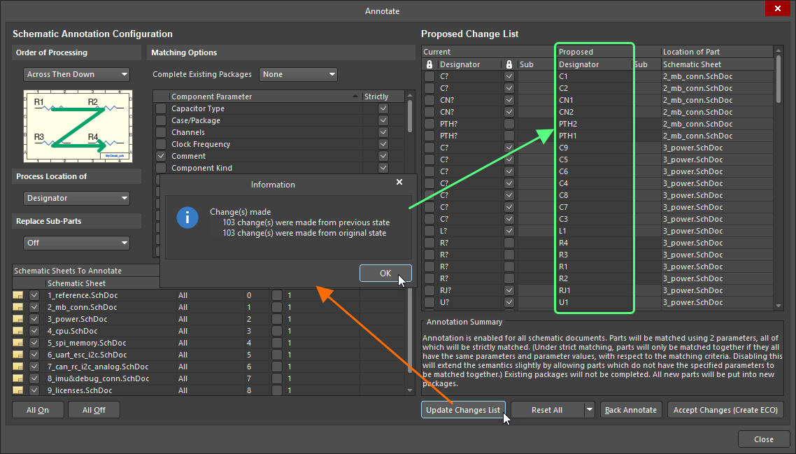
- The Proposed Change List region of the dialog (the right-hand side of the dialog), the Current and Proposed states of the designators. The proposed changes that will occur once accepted and executed using an Engineering Change Order (ECO) are listed. Click the Update changes list button to update the list so that all designator changes can be reviewed prior to being applied.
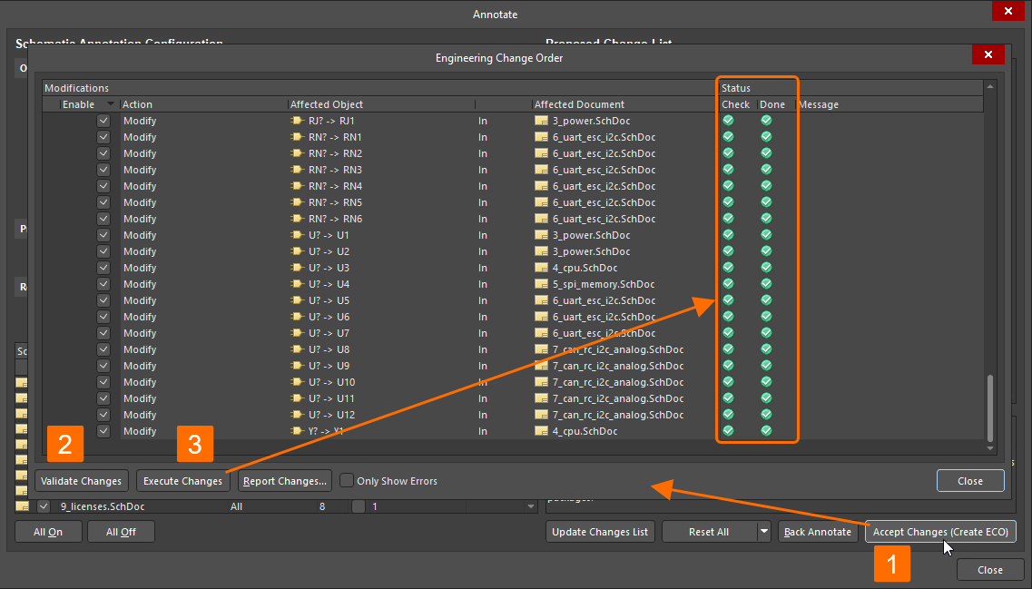
- After reviewing the list of proposed changes, click the Accept Changes (Create ECO) button to launch the Engineering Change Order dialog.
- In the Engineering Change Order dialog, click the Validate Changes button, then the Execute Changes button.
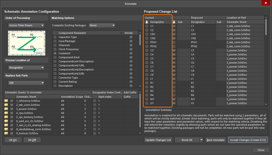
- Once the ECO is executed, the annotation changes will be applied to the design. At this stage, you can close the Engineering Change Order and Annotate dialogs.
|
In the Annotate dialog, configure how annotation should proceed. Click the Update Changes List button to update the Proposed column according to the settings. Click Accept Changes (Create ECO), then click Validate Changes and Execute Changes in the Engineering Change Order dialog. Once the ECO is executed, the changes are applied. You can now see the updated designators in the Current column (and in the design itself). |
Verifying the Design
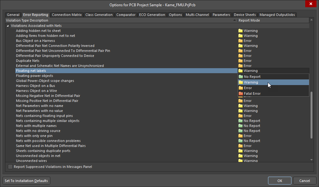
Altium Designer can check the design for logical, electrical and drafting errors in accordance with the settings on the Error Reporting and Connection Matrix tabs of the Project Options dialog accessed by right-clicking the project entry in the Projects panel and selecting Project Options.
For each specific violation type, the severity level can be specified: No Report, Warning, Error, or Fatal Error.
-
On the Error Reporting tab, select the required level by clicking in the Report Mode column for the violation check of the interest and choosing an option from the drop-down.
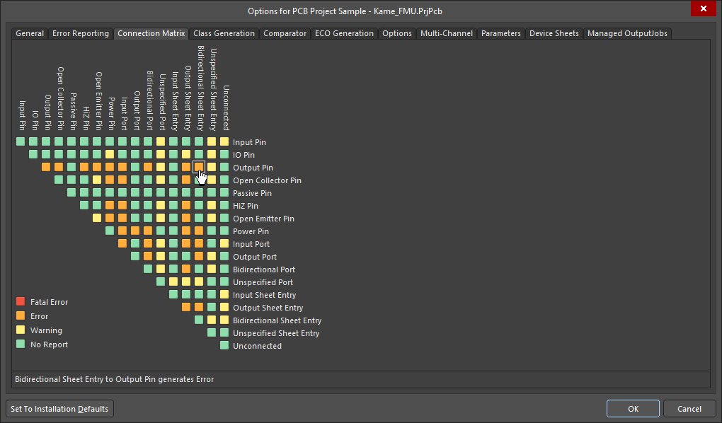
-
On the Connection Matrix tab, click on the colored square where the row and column of two entities intersect to cycle through the levels.
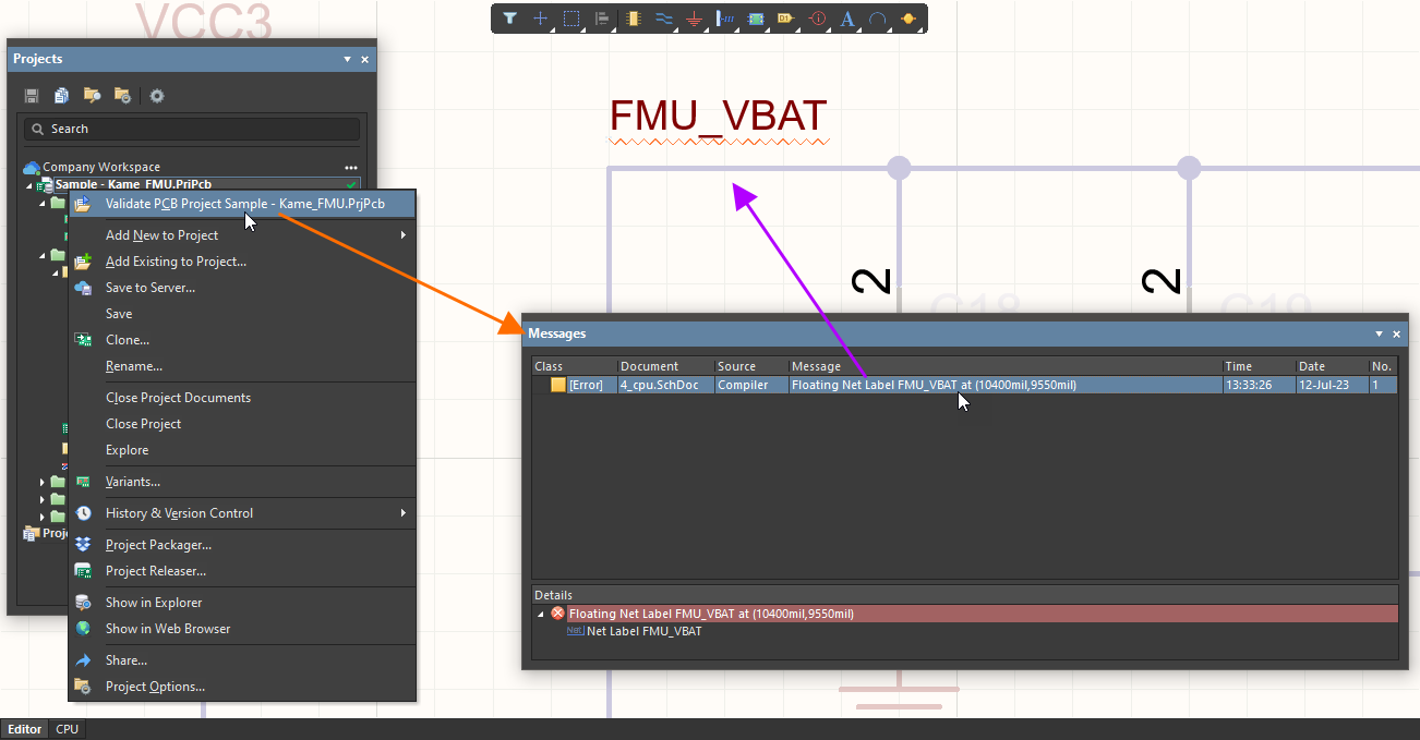
To validate your design, right-click the project entry in the Projects panel and select Validate PCB Project. Detected violations will be listed in the Messages panel.
Double-click on a message to cross-probe to that violation in the design space. After resolving violation conditions in the design, perform validation again to update the list of violations in the Messages panel.
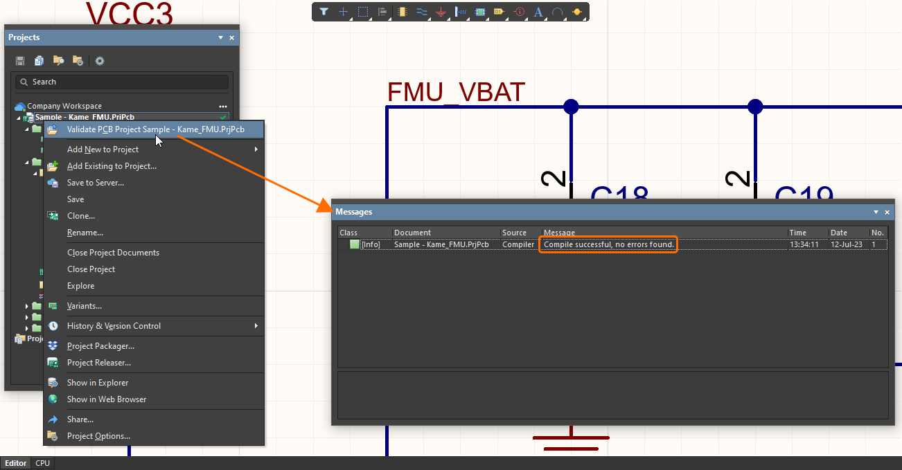
If there are no violations of the Error and Fatal Error levels, the Compile successful, no error found message will be shown in the panel.
|
Validate the design by selecting the Validate PCB Project command. Detected violations will be listed in the Messages panel. Double-click a violation message to cross-probe to it. When there are no Error or Fatal Error violations, a corresponding message will be shown in the Messages panel upon validation. |