
New in Altium Designer
At a Glance
- Explore release-by-release improvements in Altium Designer, Altium Designer Develop, and Altium Designer Agile.
- Browse new features and functionality, as well as improvements that develop and mature existing technologies.
- Understand the advanced settings options that control availability of certain features and functionality.
This page details the improvements included in releases of Altium Designer, Altium Designer Develop and Altium Designer Agile. Along with delivering a range of improvements that develop and mature the existing technologies, each update also incorporates a number of fixes and enhancements across the software based on feedback raised by customers through the AltiumLive Community's BugCrunch system, helping you continue to create cutting-edge electronics technology.
Version 26.11
Altium Designer Develop – Released: 14 October 2026 – Version 26.11.1 (build 5)
Altium Designer Agile – Released: 14 October 2026 – Version 26.11.1 (build 28)
Altium Designer – Released: 14 October 2026 – Version 26.11.1 (build 5)
Release Notes for Altium Designer
PCB Design Improvement
Enhanced Pad and Via Connection to Hatched Polygons Pours
In this release, connection of pad and vias to polygon pours with Hatched fill mode has been enhanced when a pad/via is placed inside a hatched polygon pour of the same net but in a way that it does not touch tracks of the polygon pour.
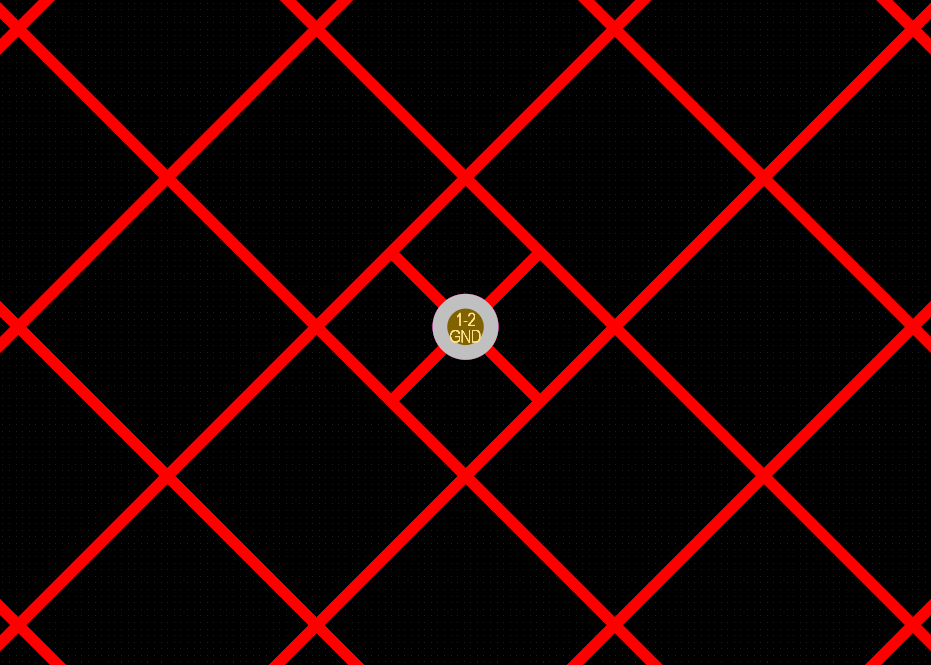
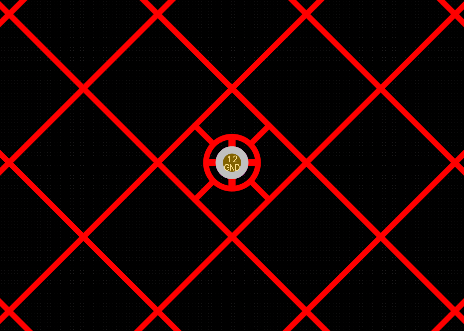
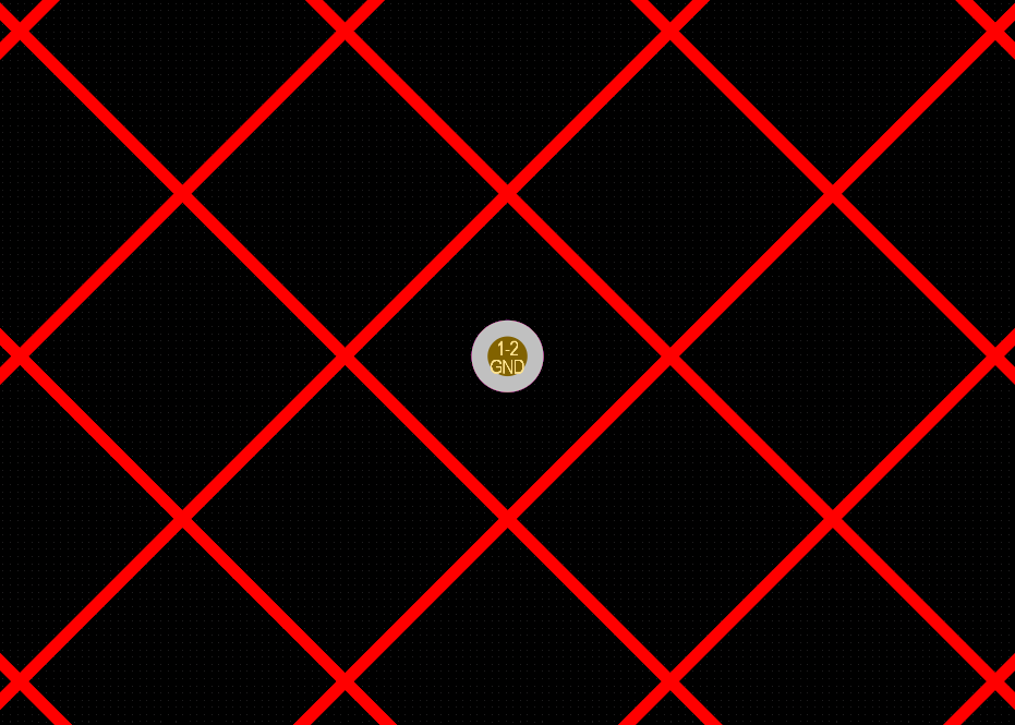
For more information about controlling the polygon connection style, refer to the Polygons on Signal Layers page.
Data Management Improvements
Added Ability to Copy/Paste System Parameters Between Component Templates
In this release, the ability to copy-paste system parameters (ComponentType, PCBLIB, SCHLIB, Name, and Description) when editing a component template has been added, with the ability to paste between template documents.
Select one or more parameters in a component template and then use the Copy command from the selection's right-click menu (shortcut: Ctrl+C). The copied parameters can then be pasted into another component template using the Paste command from the right-click menu (shortcut: Ctrl+V).
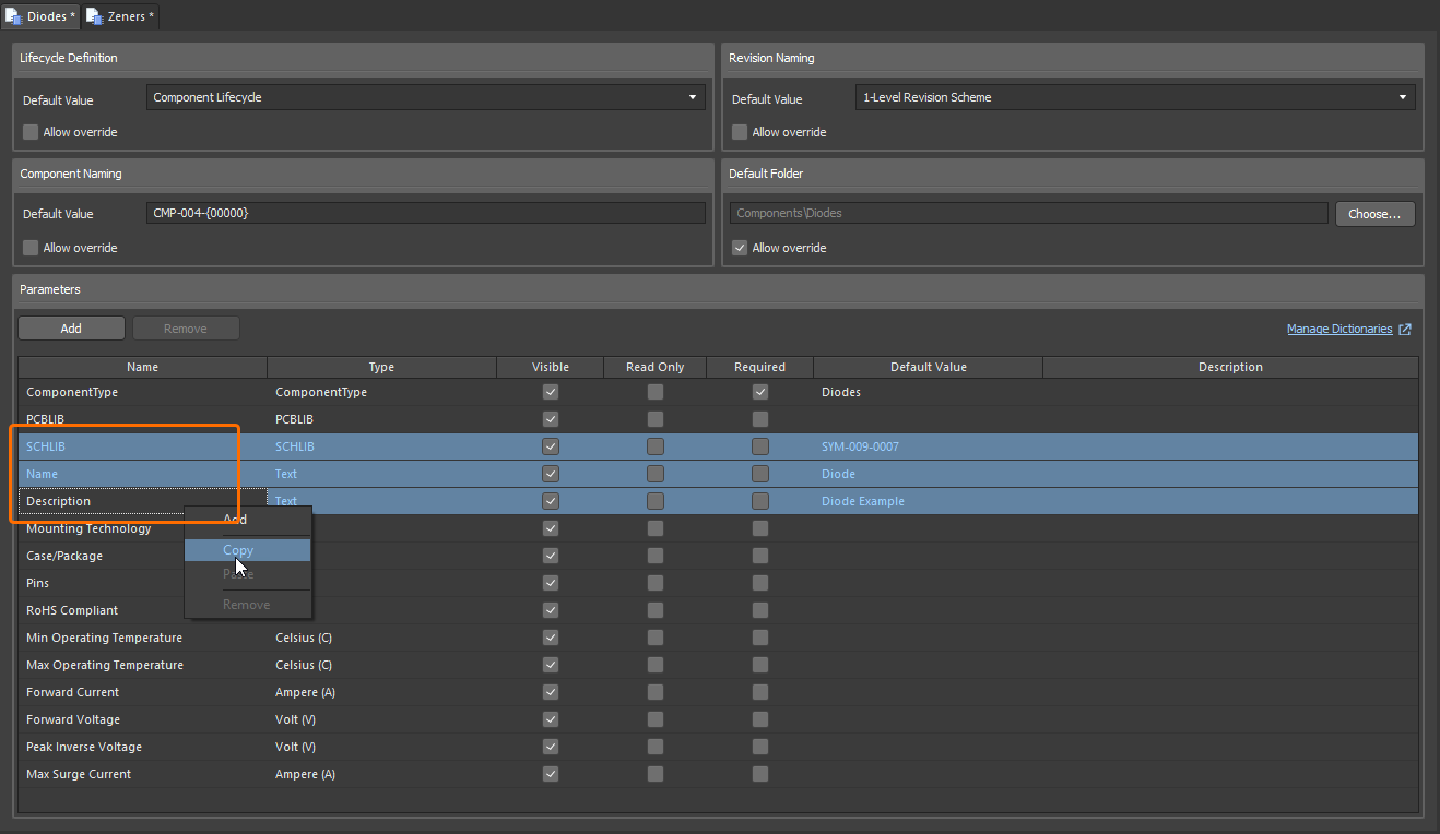
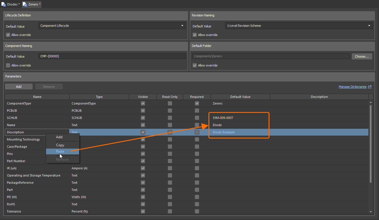
For more information about default system parameters in component templates, refer to the Component Templates page.
Enhanced Comments and Tasks Panel Filters
The filtering controls in the Comments and Tasks panel have been updated. All types (Comments, Tasks, Jira Issues) are now enabled by default. The Current document scope (which has moved from the settings window to the filter drop-down) and all assignees (assigned tasks or Jira issues) are now disabled by default. Additionally, the filter button turns blue only if the filtering state has been changed from the default, and a Clear Filters control is available to quickly return filtering to the default state.
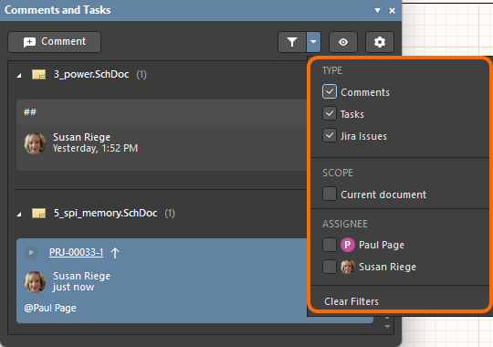
For more information about the Comments and Tasks panel filters, refer to the Document Commenting page.
Added Ability to Preserve Lifecycle State of Linked Components when Releasing
When releasing changes to a Workspace model (such as a schematic symbol or PCB footprint) into a new revision, you now have the ability (for those with assigned Allow to skip lifecycle state change for new revisions operational permission) to preserve the current lifecycle state for associated Workspace components that reference that model. The current lifecycle state of the model itself is no longer preserved. Note that this applies only to a Workspace on the Altium Platform.
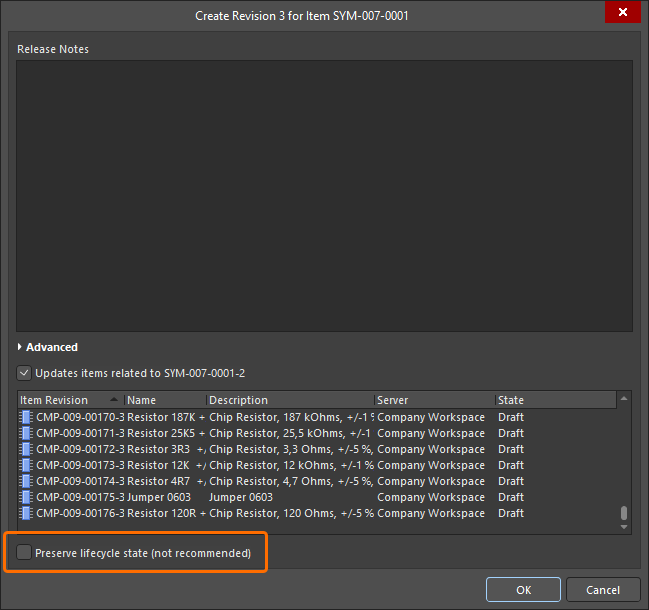
For more information about creating and editing content directly through a Workspace, refer to the Creating & Editing Content page.
Enhanced Copying of Components in Batch Component Editing
When using the Component editor in Batch Component Editing mode, and where a defined component uses parameters to define its Name and/or Description, making a copy of that component now keeps the use of those parameters in the Name/Description fields for the new component, instead of plain text.
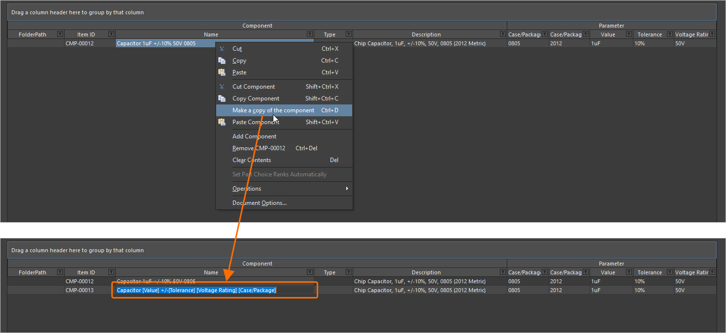
For more information about making a copy of a component definition, refer to the Batch Component Editing page.
Version 26.10
Altium Designer Develop – Released: 9 September 2026 – Version 26.10.1 (build 6)
Altium Designer Agile – Released: 9 September 2026 – Version 26.10.1 (build 26)
Altium Designer – Released: 9 September 2026 – Version 26.10.1 (build 5)
Release Notes for Altium Designer
Key Highlights
PCB Design Improvement
Design Rule Sets (Open Beta)
This release introduces the concept of Rule Sets to the PCB Rules and Constraints Editor dialog, allowing for the efficient grouping and reuse of a set of design rules specific to, for example, an interface or manufacturer. You can quickly:
-
Create a new rule set or duplicate an existing set (and then modify further as required).
-
View and manage the constituent rules within a set, with the ability to move a rule between sets.
-
Switch between applied sets of rules – enabling/disabling sets as desired.
-
Rename or delete a rule set.
-
Export/import rule sets for optimal portability. When importing, you can choose to import rules in a set to an existing rule set or to a newly-created one. In addition, import allows you to choose whether, for a same-named rule set, the rules in the imported set should be merged (added) into the existing set (and adding a suffix to any same-named rules), whether all selected rules should be added (and, in case of a conflict, an existing design rule will be replaced with the rule from the file), or whether the rules in the existing set should be removed and replaced fully by those in the imported set.
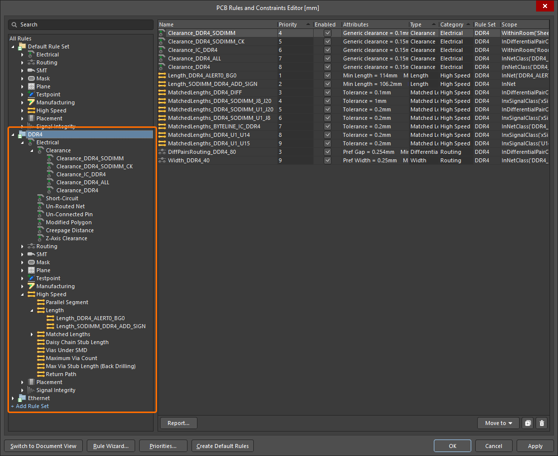
DDR4 and Ethernet rules sets have been defined to group design rules related to the corresponding interfaces.
The priority system works as before. In each rule set, only one rule of a given type (with the highest priority) is evaluated. Design rules of each type have a 'global' priority list across all rule sets, meaning that if an object in the PCB document is covered by more than one rule, the highest priority rule will apply, irrespective of the rule set to which it belongs.
In addition, the Design Rule Checker dialog includes a new Rule Sets to Check page, from where you can configure force batch checking for rule sets (provided more than one rule set exists). When the Force Batch Check option is enabled for a rule set, not only an applicable rule of the highest priority for each rule type will be checked, but also an applicable rule of the highest priority for each rule type, within this rule set, will be force-checked during Batch DRC. Essentially, force-checking runs in parallel to normal batch DRC, executing an additional DRC run for each rule set included for force checking (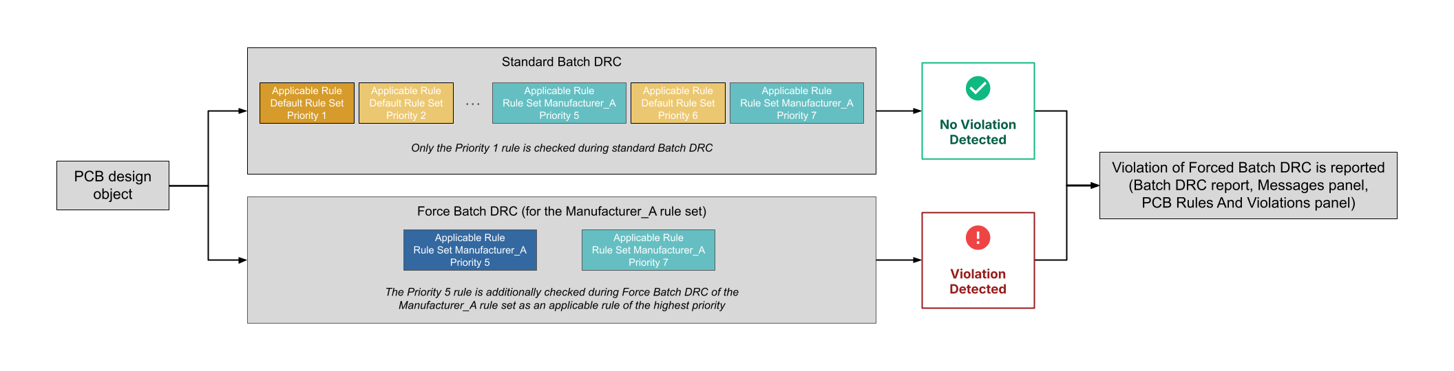 ).
).
The PCB Rules And Violations panel and Messages panel, as well as the Design Rule Verification Report, have also been updated to include rule set information.
For example, if a net is scoped by a Width rule in the Default Rule Set and a Width rule in a user-created rule set, this net will be additionally checked against the Width rule from the user-created rule set if the Force Batch Check option is enabled for this rule set, even if this rule has a lower priority than the Width rule from the Default Rule Set. Entries for detected violations of design rules that are included in force-checked rule sets are labeled Force Checked <RuleSetName> in the DRC report, the Messages panel, and the PCB Rules And Violations panel.
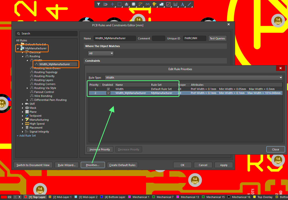
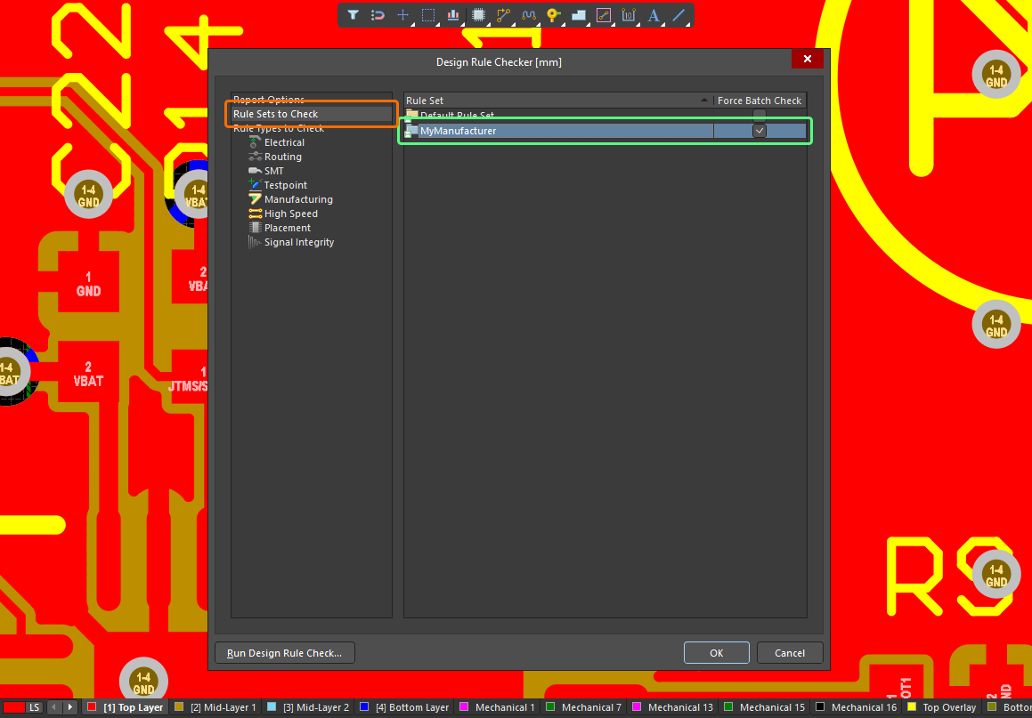
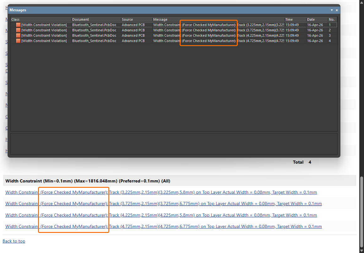
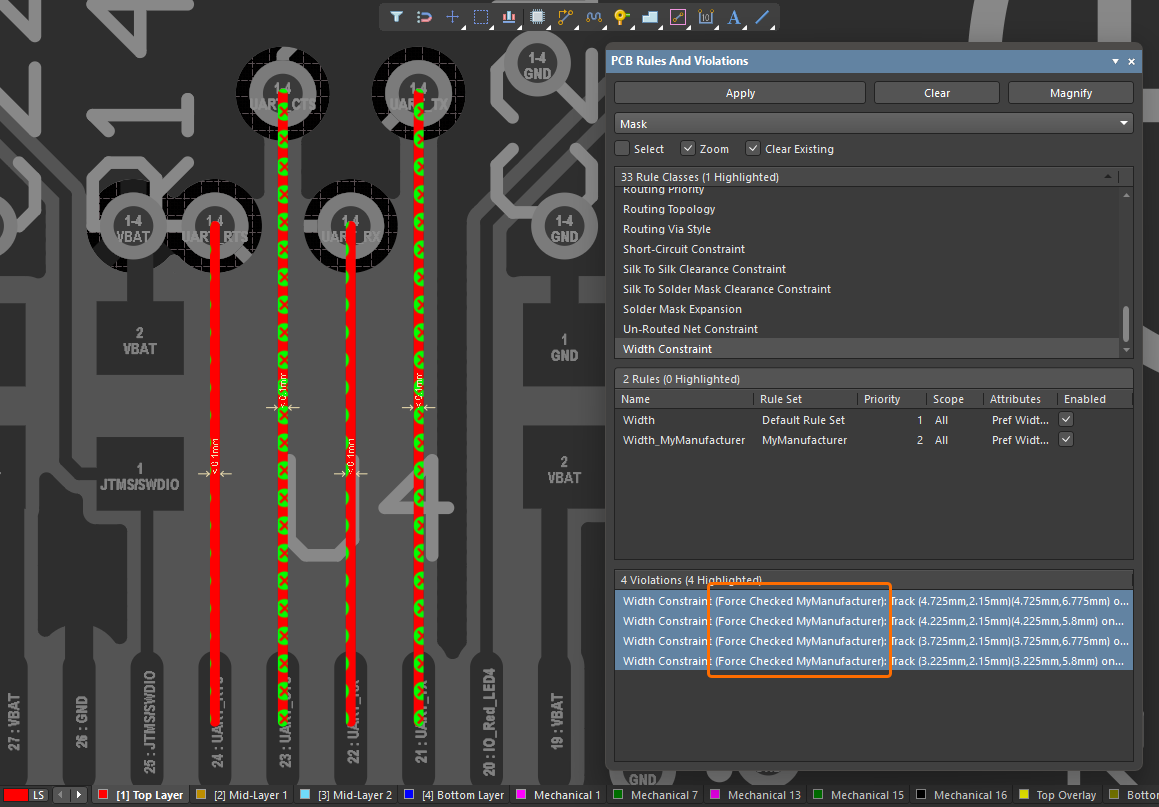
For more information, refer to Defining, Scoping & Managing PCB Design Rules and Setting Up & Running a DRC pages.
Harness Design Improvements
Layout Label Follows Bundle Orientation
Layout labels now automatically observe the orientation of the harness bundle to which they are attached. The layout label 'snaps' to the bundle in order to mimic the orientation and path. During or after placement of the layout label, you can press the Spacebar to rotate the label in increments of 90 degrees at a time or update the Rotation value in the Properties panel.
If you do not want the label to follow the orientation of the bundle (i.e. not 'snapped'), press the Alt key during placement to place the label in the required location, as shown in the video below.
When the bundle that includes a 'snapped' label is moved, the layout label position is recalculated and follows the bundle.
For more information, refer to the Creating the Layout Drawing page.
Ability to Independently Adjust Width/Height of Some Harness Objects
You can now adjust the width and height of a cable, shield or twist object that is placed in a harness wiring diagram (*.WirDoc). A new lock control associated with the Width/Height fields in the Properties region of the Properties panel (with an object selected) allows you to switch between locked or unlocked dimensions. When the object is dragged by its editing handles, the aspect ratio is followed according to the setting. The default is locked, which gives a height:width aspect ratio of 2:1 (for a cable or shield) or 1:1 (for a twist). When unlocked, you can independently change the dimensions as required.
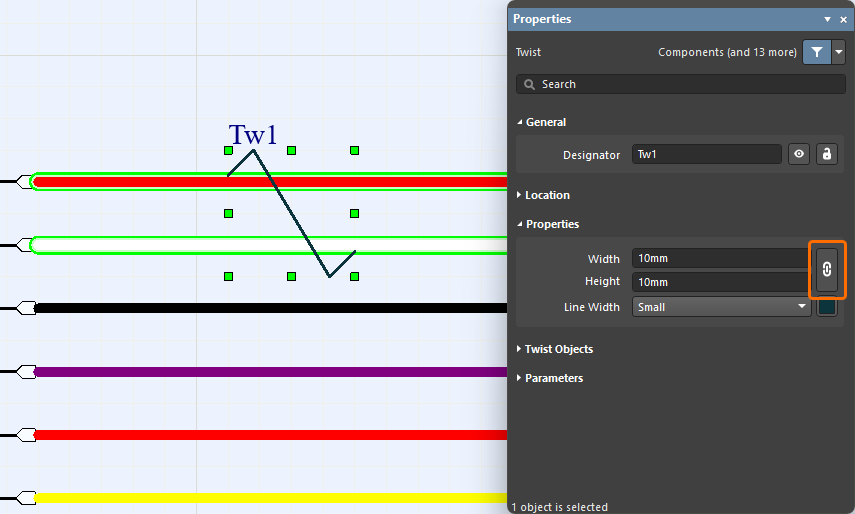
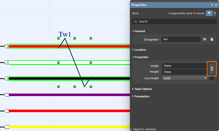
For more information, refer to the Defining the Wiring Diagram page.
Data Management Improvements
Defining Component Name and Description Using Parameters
It is now possible to use parameters to define the Name and/or Description when creating a new component (or editing an existing released component) in the connected Workspace (e.g., [ParameterName1]_[ParameterName2]), provided the parameters (with values) have been defined for the component. This feature is supported in both Single Component Editing and Batch Component Editing modes of the Component editor.
In the example shown below, the Name field of a capacitor component is defined based on its Value, Tolerance, Voltage Rating, and Case/Package parameters.
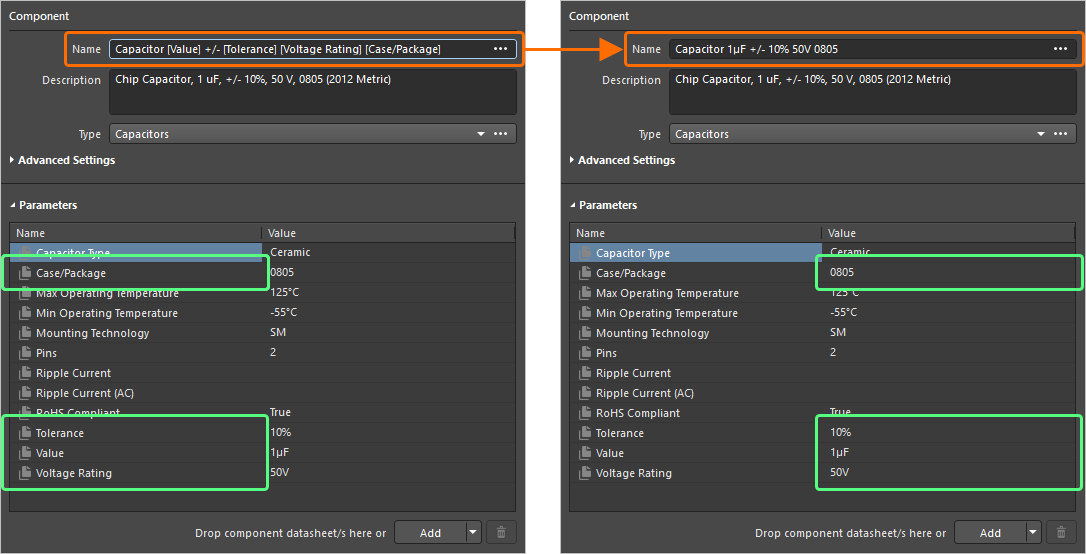
For more information, refer to the Single Component Editing and Batch Component Editing pages.
Enhancements to Custom Parts Provider Synchronization
The Custom Parts Provider Synchronization feature has been enhanced to include additional Category and Datasheet system parameters, as well as support for custom parameters, in an underlying Custom Parts Provider Synchronization Configuration document (*.PrtSync).
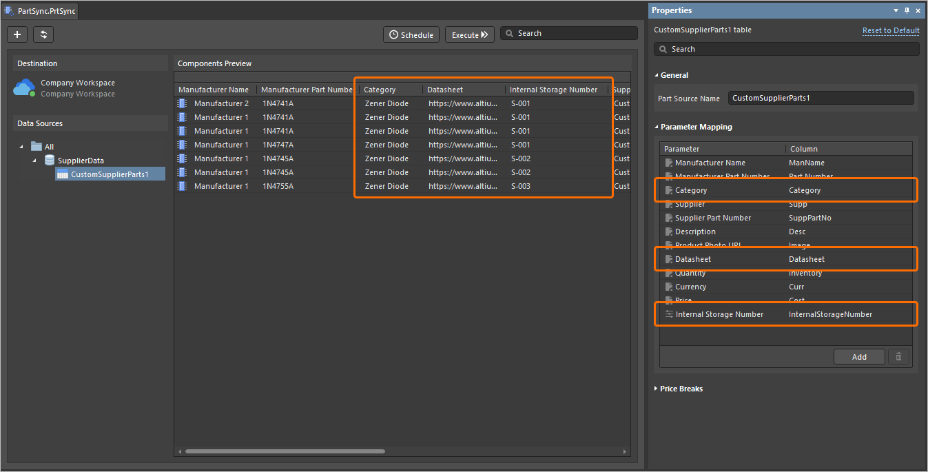
Support for these parameters has also been added to the Manufacturer Part Search panel. This requires the EDMS.CustomOffersMerge option to be enabled in the Advanced Settings dialog, which merges supplier data from your configured Custom Parts Provider with the Altium Parts Provider, to present all supplier information combined (Note: This 'Supplier Data Merging' feature is only available when connected to a Workspace on the Altium Platform that has BOM Portal enabled).
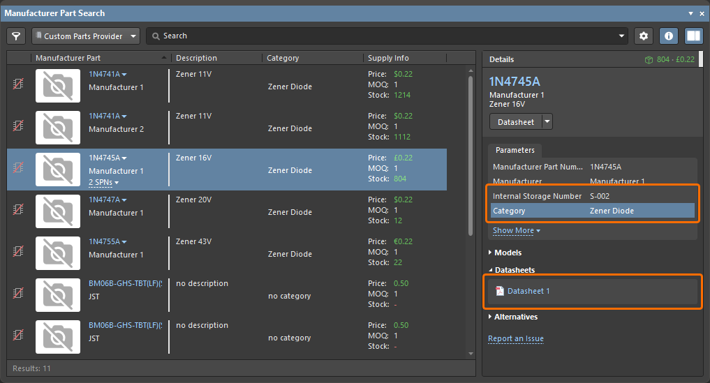
For more information, refer to the Supply Chain Database to Workspace Data Synchronization page.
Improved Name Field Search Functionality
When using the Component editor in Single Component Editing mode, the Name field has been enhanced with respect to its search functionality. Searching will now only begin after entering at least two characters, with hint text to highlight this.
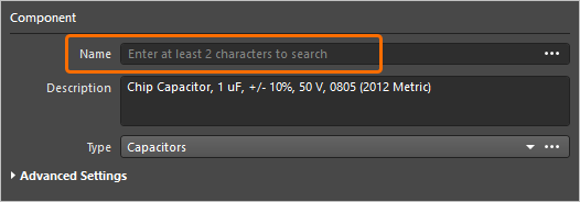
For more information, refer to the Single Component Editing page.
Feature Made Fully Public in Altium Designer 26.10
The following feature is now officially Public with this release:
Additional Feature in Altium Designer 26.10
-
Open CASCADE 7.9.0 (Open Beta): A new advanced settings option –
PCB.UseOpenCascade790– is available in the Advanced Settings dialog with this release which, when enabled, switches to use version 7.9.0 of the Open CASCADE library for processing of 3D geometry in Altium Designer.
Version 26.9
Altium Designer Develop – Released: 5 August 2026, Version 26.9.1 (build 9)
Altium Designer Agile – Released: 5 August 2026, Version 26.9.1 (build 46)
Altium Designer – Released: 5 August 2026, Version 26.9.1 (build 10)
Release Notes for Altium Designer
Key Highlights
PCB Design Improvements
Advanced Polygon Pouring (Open Beta)
In this release, a new polygon pour engine has been introduced. This engine not only improves quality and performance but also produces 'true arcs' instead of approximations.
With true arcs used in polygon pours, the Arc Approx. (for solid polygon pours) and Optimal Void Rotation options are no longer available in the Properties panel when a placed polygon pour is selected (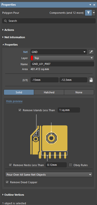 ).
).
For more information about polygon pour properties, refer to the Polygons on Signal Layers page.
Dynamic Polygon Pouring (Open Beta)
The dynamic polygon pour feature repours the polygon as you route rather than after routing modifications have been made. This feature allows you to repour polygons on the fly (dynamic pouring) during interactive commands (i.e. interactive routing or interactive sliding). Solid, hatched, and unfilled polygon pours are supported.
To use dynamic polygon pouring, the Repour Polygons After Modification option on the PCB Editor – General page of the Preferences dialog must be enabled.
For more information, refer to the Polygons on Signal Layers page.
Support for Rendering of True Arcs (Open Beta)
This release adds support for true arcs generated in both the PCB editor and PCB Library editor design space, instead of approximations. This support extends across 2D/3D Layout Modes (and Board Planning Mode for the PCB editor). True arc rendering can be seen in action in the following areas:
-
Polygon pours (solid, hatched, none)
-
Polygon pour cutouts
-
Selection contour for polygon pours and regions
-
Regions
-
Solder mask and paste mask expansions
-
Net highlighting
-
Clearance boundaries
-
Violation overlay (separate polygon pour on region or polygon pour)
Examples of true arc rendering of polygon pours poured around other objects of a PCB are shown below.
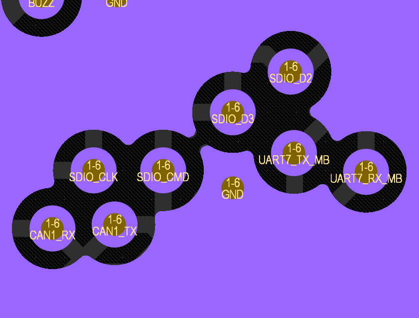
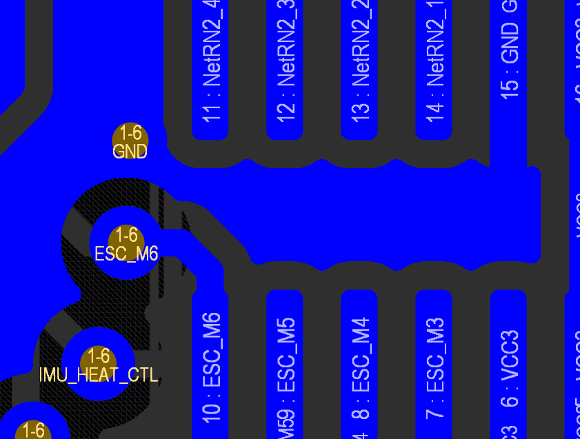
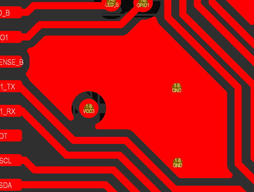
For more information, refer to the PCB Placement & Editing Techniques page.
Updated Options When Importing Rules
When importing one or more rule sets (in a *.rul file) with the same name(s) as those that already exist, three actions are now available in the Rule Set Already Exists dialog to handle the imported rules within a set:
-
Add to existing rules – choose to import all selected rules; in case of a conflict (a rule with the same name already exists in the design), a rule from the file will be imported with the
_<n>suffix in its name. -
Add and replace matching rules – choose to import all selected rules; in case of a conflict, an existing design rule will be replaced with the rule from the file.
-
Replace all – choose to remove all existing rules in the rule set and import all selected rules.
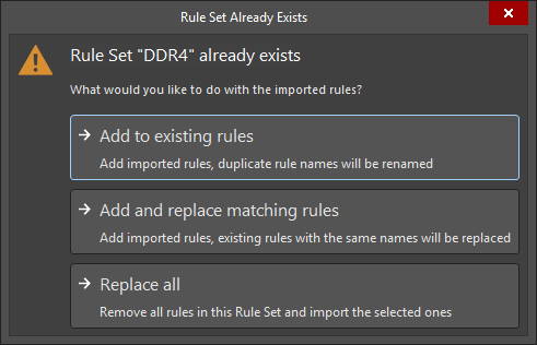
If there is more than one rule set that already exists in the PCB, you can choose one of the options above for each rule set using the Some Rule Sets Already Exist dialog that opens.
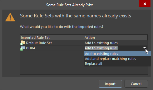
For more information, refer to the Defining, Scoping & Managing PCB Design Rules page.
Harness Design Improvements
Ability to Reassign Bundle Objects
You can now reassign bundle objects in a layout drawing where a wire could traverse more than one path between its source and destination connectors. By default, the wire will automatically be assigned to the shortest bundle path, but now you have the ability to override this. A new Assign Objects to Bundle control appears at the bottom of the Bundle Objects section of the Properties panel (with the bundle selected in the design space), and only when an alternative routing path exists. The Assign Objects to Bundle dialog opens in which you can select objects (wires/cables) to move between the applicable and valid bundles.
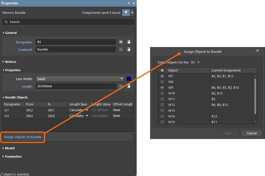
As part of this functionality, the Objects assigned to the bundle drop-down and related object selection entries in the Bundle Objects Assignment region of the Properties panel have been removed.
For more information about harness bundles, refer to the Creating the Layout Drawing page.
Added Custom Values for Rotating a Physical Model View
Previously, rotation of a physical model view in a layout drawing (*.LdrDoc) using the Rotation field when configuring the Physical View in the Properties panel was constrained to choices of 0/90/180/270 degree values. With this release, you now can enter a custom value for rotation. This feature gives you much more flexibility in positioning the view.
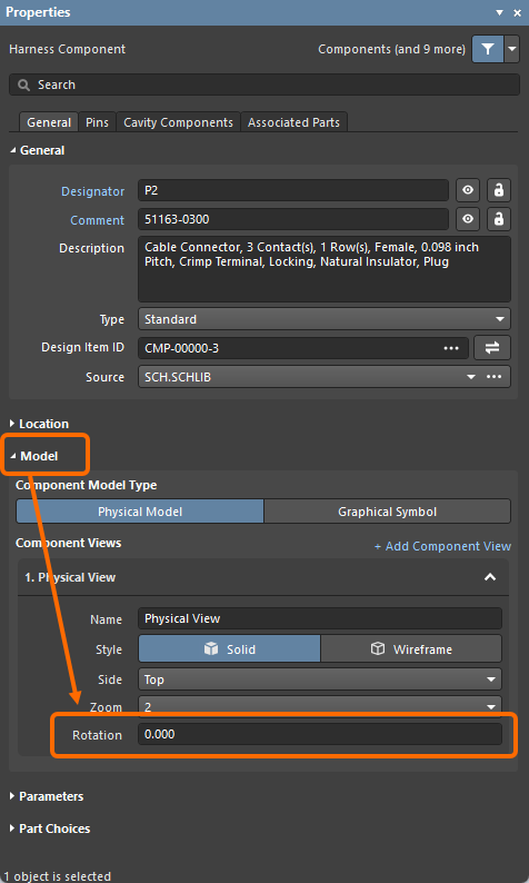
A physical model view can also be rotated graphically in the design space by grabbing a rotation handle located at the bottom right of the model view and using the mouse; the Rotation field will automatically update (rotation is in 1 degree increments). You can also hold the Alt key to constrain rotation to 45 degree increments. As a helpful guide, when the view is being rotated with the mouse, the current angle is displayed in the Status Bar.
 ).
).For more information about physical model views, refer to the Creating the Layout Drawing page.
Added Bundle Segment View
The new bundle segment view added in this release displays the wires that are inside the bundle segment, i.e. individual wires, twisted pairs of wires, and wires that are part of cables. This allows you to see exactly how the wires physically fit together inside the harness bundle segment. Each wire is labeled and colored using the wire's defined color, as well as its thickness based on the value for its Thickness parameter (defined on the wiring diagram (*.WirDoc)). You can place a segment view of a placed bundle segment into a layout drawing (*.LdrDoc) using the +Add Segment View command in the Model region of the Properties panel. The Segment View region then displays a drop-down in which you can select the Zoom level for the added view. The design space then zooms into the view as shown in the example slideshow below. To delete a segment view, use the Delete command in the Segment View region. Click to select the view and move it to the desired location on the design space.
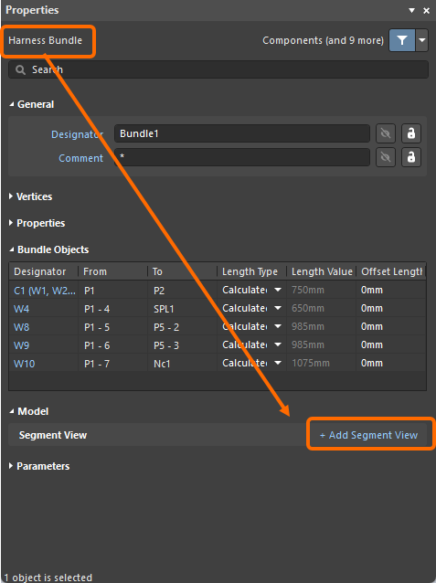
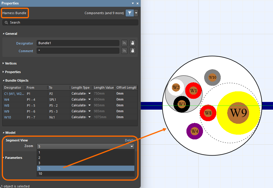
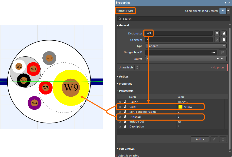
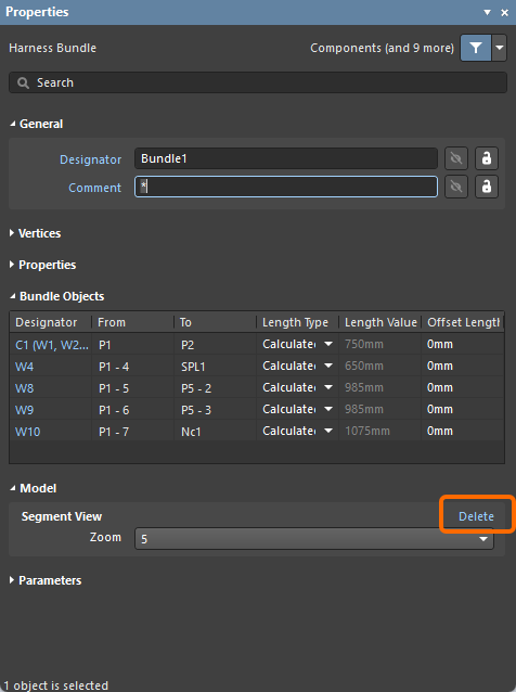
For more information about the new bundle segment view, refer to the Creating the Layout Drawing page.
Import/Export Improvement
Support for Variants in OrCAD Importer
The OrCAD Importer has been enhanced to support importing variants defined in an OrCAD design. This improvement ensures the imported project includes the same list of variants as in OrCAD.
For more information about the OrCAD Importer, refer to the Importing a Design from OrCAD page.
Feature Made Fully Public in Altium Designer 26.9
The following feature is now officially Public with this release:
Version 26.8
Altium Designer Develop – Released: 9 July 2026 – Version 26.8.1 (build 9)
Altium Designer Agile – Released: 9 July 2026 – Version 26.8.1 (build 50)
Altium Designer – Released: 9 July 2026 – Version 26.8.1 (build 31)
Release Notes for Altium Designer
Key Highlights
PCB Design Improvement
Increased Number of Signal Layers (Open Beta)
In this release, the number of signal layers that can be present in a PCB design has been increased from 32 to 128. This scenario is often a necessity for, and particularly suited to, larger and more complex designs.
As you would expect, all areas of the software impacted by this extended layer support, and in particular the PCB editor, have been updated to provide for it, including the Layer Stack Manager, View Configuration panel, Properties panel, filtering, DRC, output generation, and so on. Some examples of affected areas are shown in the slideshow below.
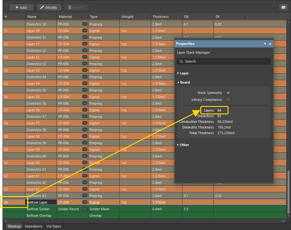
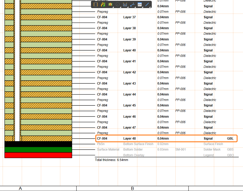
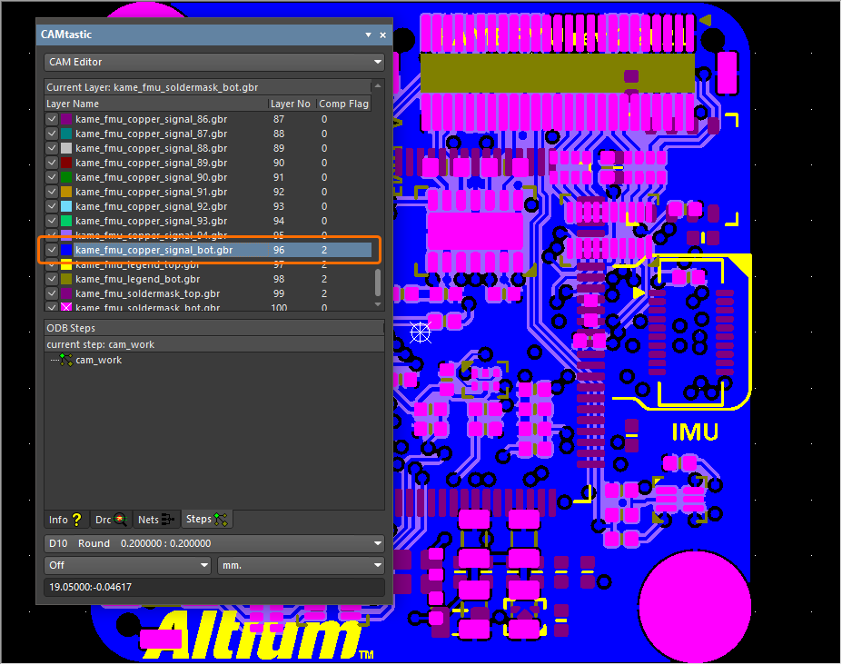
For more information, refer to the Defining the Layer Stack page.
Constraint Manager Improvement
Enhanced Clearance Rule Mode Control
When creating an advanced Clearance rule from the All Rules view when accessing the Constraint Manager from the PCB, new controls have been added that allow you to switch between ‘Simple’ and ‘Advanced’ modes of operation for the minimum clearance matrix (similar to the PCB Rules and Constraints Manager dialog). In Simple mode, Track and Arc objects (including Track Keepout and Arc Keepout objects) are combined into the single ‘Track’ entry. Fill, Poly, and Region objects (including Fill Keepout and Region Keepout objects) are combined into the single ‘Copper’ entry. Note that the entry for ‘Text’ objects is hidden in this mode. In Advanced mode, all objects are presented.

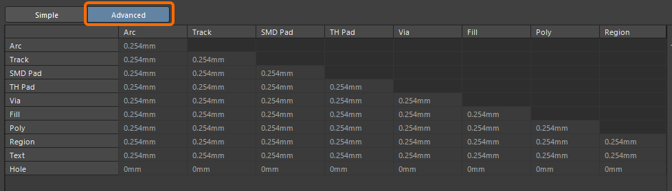
For more information about creating an advanced rule, refer to the Defining Design Requirements Using the Constraint Manager page.
Draftsman Improvement
Added Panning 'Hand' Cursor
A 'hand' cursor is now displayed when panning a Draftsman-based manufacturing drawing document (*.PCBDwf, *.HarDwf, *.MbDwf) using the Right-click, Hold&Drag function, which aligns with the Schematic and PCB editors.
For more information, refer to the Shortcuts for the Altium Designer Draftsman Editor page.
Import/Export Improvement
Advanced OrCAD Engine (Open Beta)
This release introduces a new, advanced OrCAD Engine when importing your OrCAD designs and libraries using the Import Wizard.
For more information, refer to the Importing a Design from OrCAD page.
Features Made Fully Public in Altium Designer 26.8
The following features are now officially Public with this release:
Version 26.7
Altium Designer Develop – Released: 8 June 2026 – Version 26.7.1 (build 13)
Altium Designer Agile – Released: 8 June 2026 – Version 26.7.1 (build 25)
Altium Designer – Released: 8 June 2026 – Version 26.7.1 (build 11)
Release Notes for Altium Designer
Key Highlights
Wire Bonding Improvement
Controlling Visibility of Bond Wires and Die Pads (Open Beta)
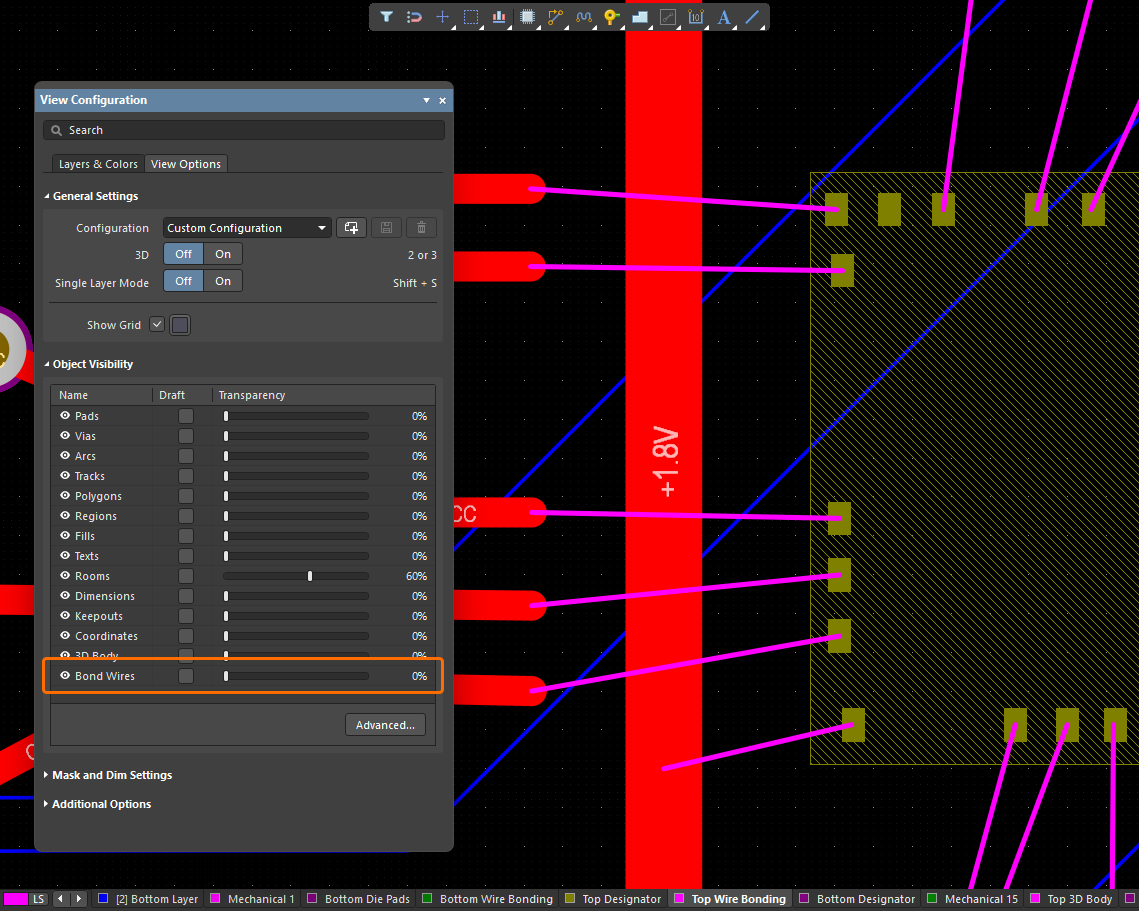
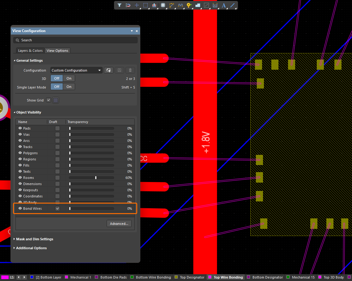
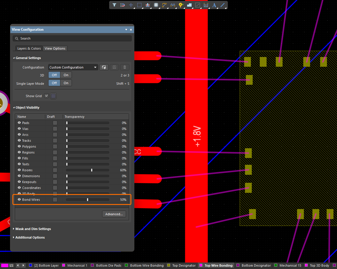
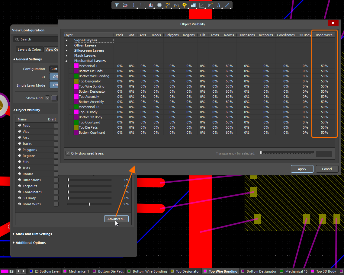
When viewing a PCB in 2D Layout Mode, you can now control the visibility of bond wires using the new Bond Wires entry (and associated controls) in the Object Visibility region on the View Options tab of the View Configuration panel.
When viewing a PCB in 3D Layout Mode, the visibility of bond wires and die pads is now controlled as part of the Show 3D Bodies option in the General Settings region on the View Options tab of the View Configuration panel.
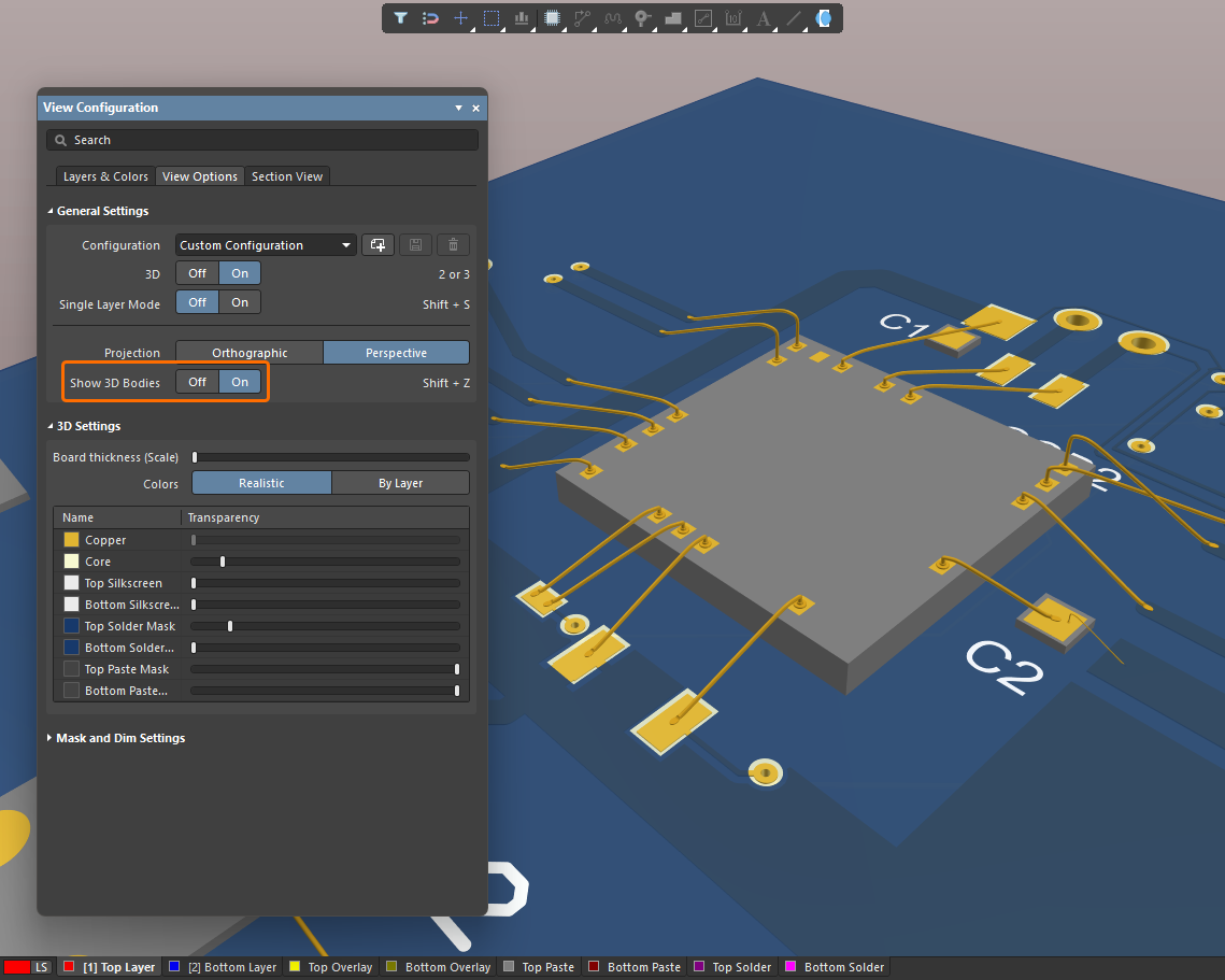
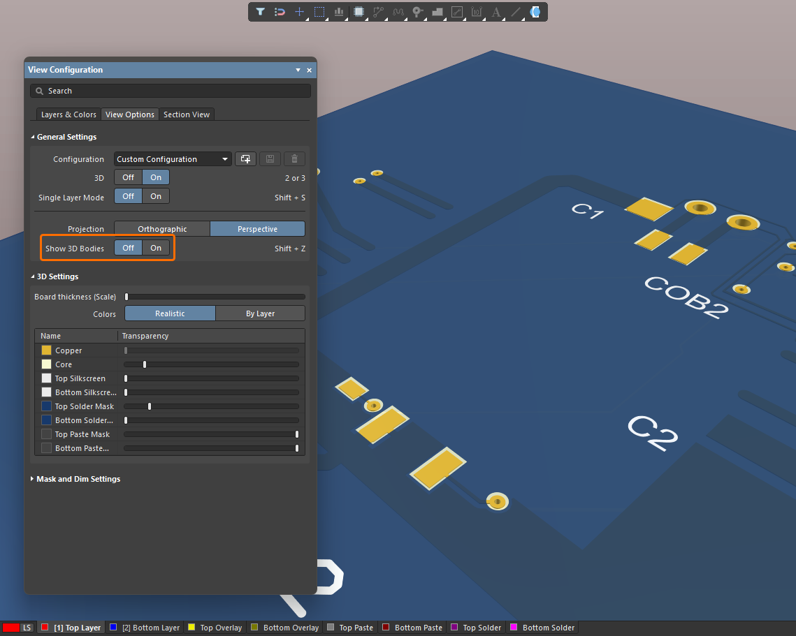
For more information about wire bonding, refer to the Wire Bonding page.
Platform Improvement
Ability to Roam an Author Seat in Altium Designer Develop
An Administrator of an Altium Develop Workspace can now reserve an author seat for a specified Workspace Member using the Admin – Usage and Billing page of the Workspace's browser interface. This allows the Workspace Member to work with Altium Designer Develop (26.7 and later) offline, without being connected to the Altium Develop Workspace or signed in to their Altium Account, for the duration of subscription. At any time, a Workspace Administrator can revoke that roamed seat.
When an author seat is being used in roaming mode in Altium Designer Develop, the  icon is shown next to the Active Server control.
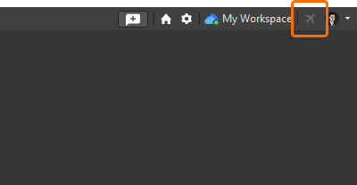
For more information, refer to the Authoring Access in Altium Designer Develop page.
Features Made Fully Public in Altium Designer 26.7
The following features are now officially Public with this release:
Version 26.6
Altium Designer Develop – Released: 19 May 2026 – Version 26.6.0 (build 14)
Altium Designer Agile – Released: 19 May 2026 – Version 26.6.0 (build 21)
Altium Designer – Released: 19 May 2026 – Version 26.6.0 (build 10)
Release Notes for Altium Designer
Key Highlights
PCB Design Improvement
Updated IPC Compliant Footprint Wizard Packages
Updated All Packages for Compliance with IPC Standard 7351, Revision B
The IPC Compliant Footprint Wizard has been updated for all existing supported packages to ensure footprint generation is in accordance with Revision B of the IPC Standard 7351 - Generic Requirements for Surface Mount Design and Land Pattern Standard. Several areas have been updated for compatibility. These include (but are not limited to):
-
Pad size and gap formulas
-
Stacking rounding issue
-
Layer mapping
-
Silkscreen and courtyard
-
Density table values
-
Set package outline output to maximum values
Added Ability to Control Pad Trimming for a Gullwing Package Footprint
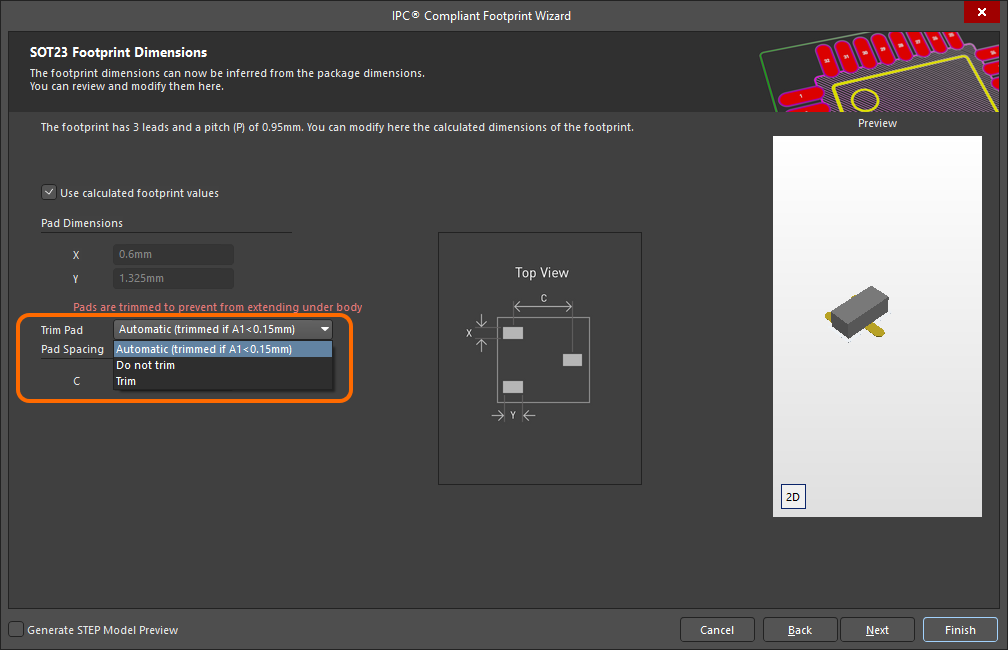
The Footprint Dimensions page of the Wizard has been enhanced with the ability to control whether or not pad trimming is applied when using calculated footprint values when generating a gullwing package footprint (SOT23 is used in the example image below). Use the Trim Pad drop-down to select the desired trimming option.
Additional Updates
-
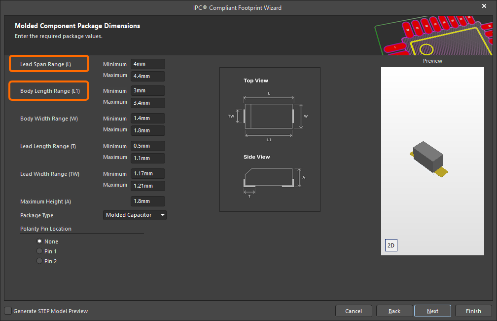
A new Lead Span Range (L) parameter has been added when defining the dimensions of a MOLDED package. This allows for specifying the minimum and maximum values for the distance between the outer sides of leads.
-
The Body Length Range (L) parameter has been renamed Body Length Range (L1) and imagery has been updated for a MOLDED package.
-
When creating a SODFL or MOLDED (polarized) package, the polarized pin (cathode) is now identified on the generated 3D STEP model by a white bar only (SODFL), or white bar and chamfer (MOLDED).
-
When creating a PQFP package footprint, the silkscreen outline is now generated using the same style/approach as for the QFN package. The outline now follows the maximum package outline with an offset towards the outside of the package outline of one half of the silkscreen line width. The default silkscreen line width is 0.127 mm.
-
When creating a PQFP or CQFP package footprint, the package outline is now built based on maximum dimension values versus nominal values, in line with SOIC, SOP, TSSOP, and SOT packages.
-
When generating a gullwing package footprint using the IPC Compliant Footprints Batch generator, a new PadTrimming parameter has been added to the Footprint Specifications section on the Data tab of the associated Excel template file to control whether or not pad trimming is applied. SOIC has been used in the image below.
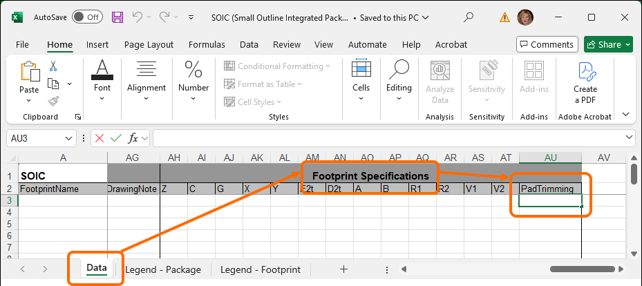
For more information, refer to the Creating a PCB Footprint page.
CAMtastic Improvement
Automatically Assign Color for Imported Gerber and ODB++ Files
Layer colors are now assigned according to the layer type (e.g., red for signal-top, blue for signal-bottom. etc.,) when Gerber and ODB++ files are imported into the CAM editor if the layer color information is missing from the files that are being imported. The new default color function has been implemented to remove instances when layers could possibly be assigned incorrect colors.
For more information, refer to the Preparing Fabrication Data page.
Harness Design Improvement
Ability to 'Split' Connection Table
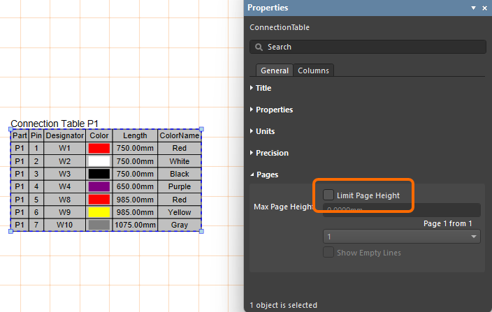
The connection table of an advanced harness design may have a large number of entries, which can be difficult to fit into a drawing document as a single table. Rather than resorting to font and table scaling, multiple custom table entries, or an external document, you now have the ability to 'split' a connection table in a Harness Draftsman document (*.HarDwf) so that the connection table will be presented over a number of 'pages.' In the Properties panel for a placed connection table, enable the Limit Page Height option in the Pages region to use the new feature. This will restrict the height of the connection table to the nominated height entry (Max Page Height) and, therefore, the number of lines shown in the table.
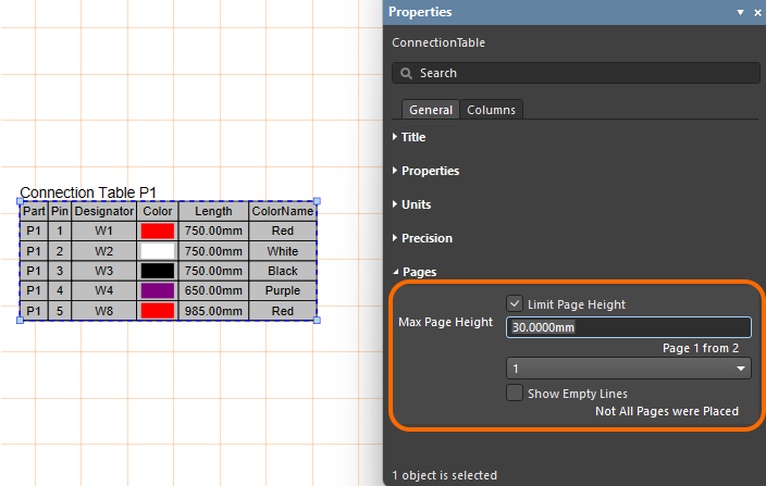
The editor detects that the entire connection table is not shown, as indicated by the panel's Page entry (for example, 1 from 2), and the associated drop-down menu allows you to nominate which page is shown. To add further pages of the connection table, place another connection table (Place » Connection Table) and specify the next Page in the Pages region of the Properties panel.
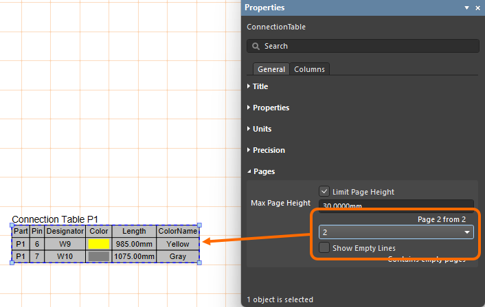
For more information, refer to the Creating a Manufacturing Drawing for a Harness Design page.
Data Management Improvements
Added Support for 'Temperature Coefficient' Data Type
When defining a user parameter as part of a component template in a connected Workspace on the Altium Platform, an additional unit-aware data type – Temperature coefficient (ppm/°C) – is now supported.
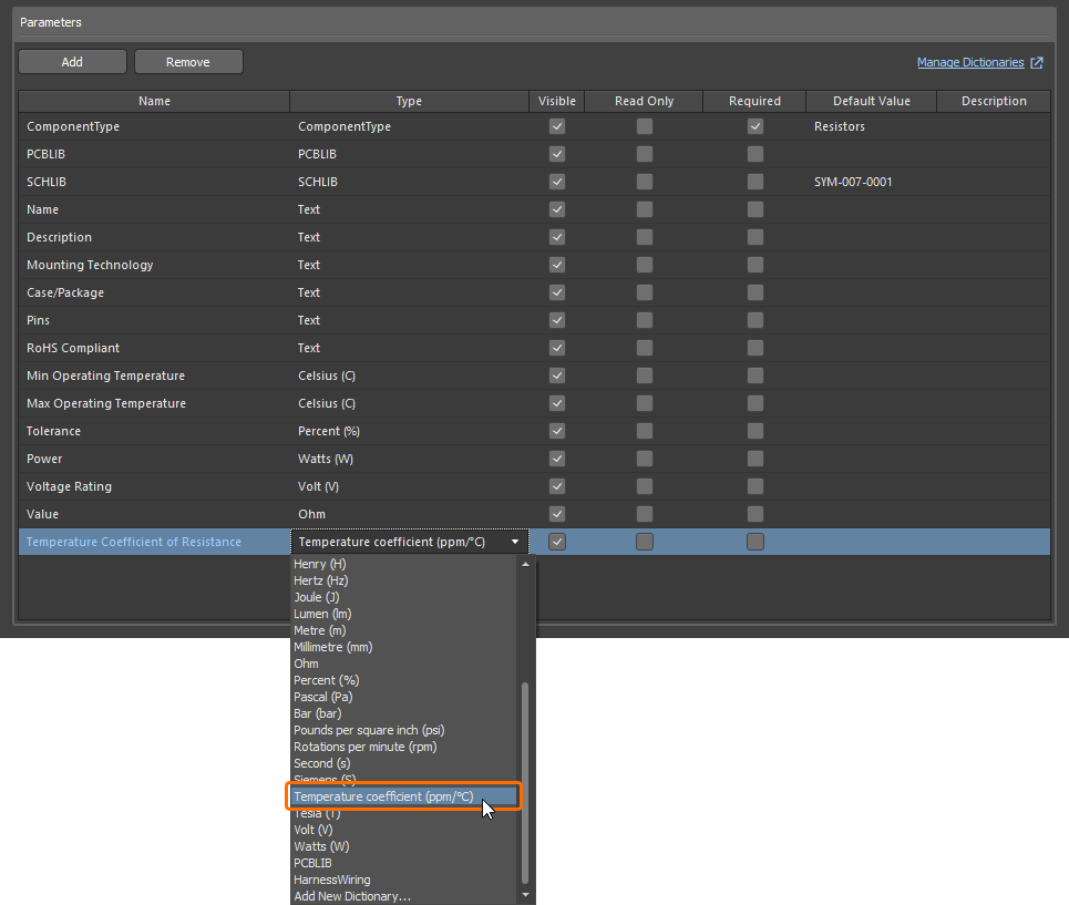
Parameters that use this new unit type are supported in various areas of the software, including the Components panel, the Component editor (in both single and batch editing modes), and by the Library Importer and Components Synchronization feature (in the Parameter Mapping section of the Properties panel).
For more information about the unit-aware component parameter data types, refer to the Component Templates page.
Ability to Change the Applied Environment Configuration
When connecting to an Altium Platform Workspace that has defined Environment Configurations, and where a user is assigned to several groups (multiple environment configurations can apply), it is now possible to change the applied configuration after having initially selected one and enabled the Remember my choice option in the Select a Configuration dialog. Catering for this, a new Connection Properties dialog, accessed from the Properties menu for the Workspace, on the Data Management - Servers page of Preferences, enables you to quickly change the configuration to use, from those available to you.
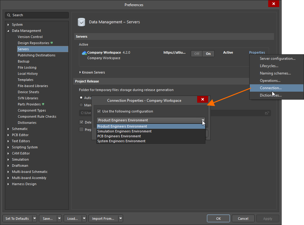
For more information about application of environment configurations, refer to the Accessing Your Workspace page.
Import/Export Improvement
Advanced Allegro Import Wizard (Open Beta)
This release introduces the enhanced Allegro Import Wizard that supports the import of padstack-level solder and paste masks for pads (regular and custom shapes, including tented pads) and vias (involving the calculation of expansions and including tented sides).
Also, when importing an Allegro design with the listed below defined sub-classes on Top or Bottom layers, a component layer pair is now created in the generated PCB document to accommodate values from these Top and Bottom layers, with these layers hidden by default with respect to their visibility.
Allegro Design Sub-class |
Altium Component Layer Pair |
|---|---|
Layers - Components - Comp value |
COMPONENT_VALUE_TOP and COMPONENT_VALUE_BOTTOM |
Layers - Components - Dev type |
DEVICE_TYPE_TOP and DEVICE_TYPE_BOTTOM |
Layers - Components - Tolerance |
TOLERANCE_TOP and TOLERANCE_BOTTOM |
Layers - Components - User part |
PART_NUMBER_TOP and PART_NUMBER_BOTTOM |
For more information, refer to the Importing a Design from Allegro page.
Feature Made Fully Public in Altium Designer 26.6
The following feature is now officially Public with this release:
Version 26.5
Altium Designer Develop – Released: 6 May 2026, Version 26.5.1 (build 12) – Additional Update
Altium Designer Agile – Released: 6 May 2026, Version 26.5.1 (build 30) – Additional Update
Altium Designer – Released: 6 May 2026, Version 26.5.1 (build 12) – Additional Update
Altium Designer Develop – Released: 8 April 2026 – Version 26.5.0 (build 11)
Altium Designer Agile – Released: 8 April 2026 – Version 26.5.0 (build 17)
Altium Designer – Released: 8 April 2026 – Version 26.5.0 (build 11)
Release Notes for Altium Designer
Key Highlights
Schematic Capture Improvement
Added Ability to Define Pin's Vertical Margin
You now define a custom vertical margin for a pin's designator and name. This gives you full control over horizontal (X) and vertical (Y) margins. Margins can be defined globally on the Schematic - General page of the Preferences dialog in the Pin Settings region in the Designator and Margin (X/Y) fields. To define margins locally, use the Margin (X/Y) fields in the Properties panel.
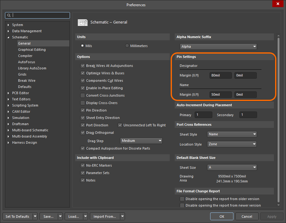
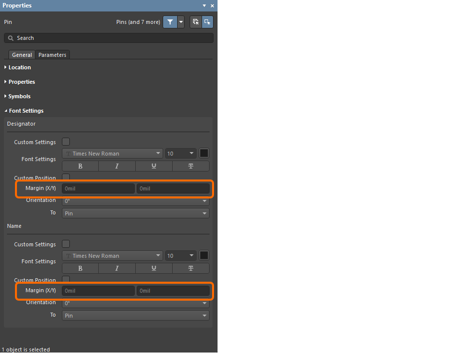
The pin's vertical margin is defined using the new Pin Designator Vertical Margin and Pin Name Vertical Margin fields in the List panels and the Find Similar Objects dialog. In addition, two new query keywords are available in the SCH Functions\Fields category – PinDesignator_CustomPosition_VerticalMargin and PinName_CustomPosition_VerticalMargin – for targeting the vertical margin of these two properties when crafting logical query expressions.
For more information, refer to the Creating a Schematic Symbol page.
PCB Design Improvement
ODB++ Intellectual Property Protection (Open Beta)
This release brings the ability to configure ODB++ setup to protect your valuable intellectual property (IP) by restricting what is generated.
In the ODB++ Setup dialog, you have the ability to select which signal layers to export as part of the generated data. In addition, you can control whether the netlist is included and, if so, whether to neutralize it (by replacing net names with Net_[1-…]). You also can control whether to include components, with the possibility to remove component properties (parameters).
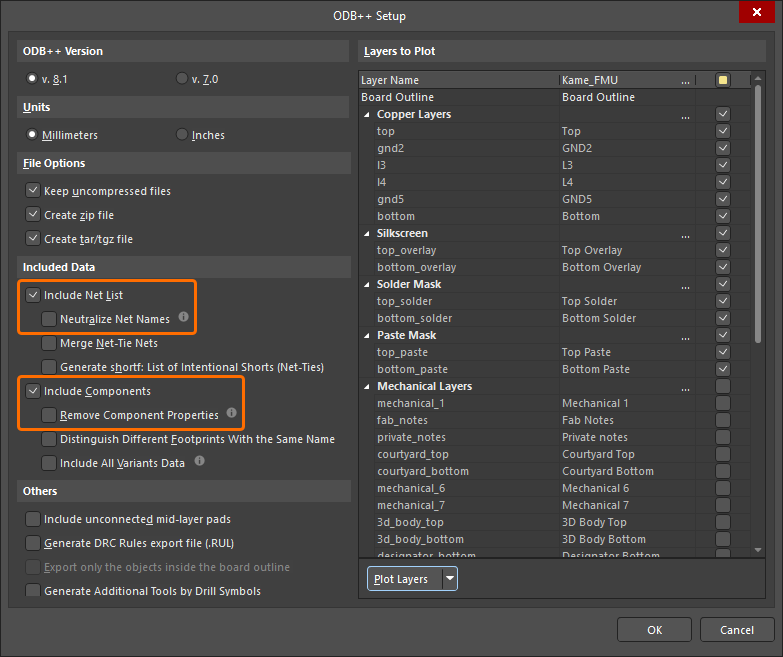
Folder path information will also be removed from generated report ([Design name].REP) and rule (odb\user\[Design name].RUL) files.
For more information about preparing ODB++ fabrication data, refer to the Preparing Fabrication Data page.
Wire Bonding Improvement
Wire Bonding 3D Enhancements (Open Beta)
This release brings enhanced support for bond wires in the 3D view of a board. This includes:
-
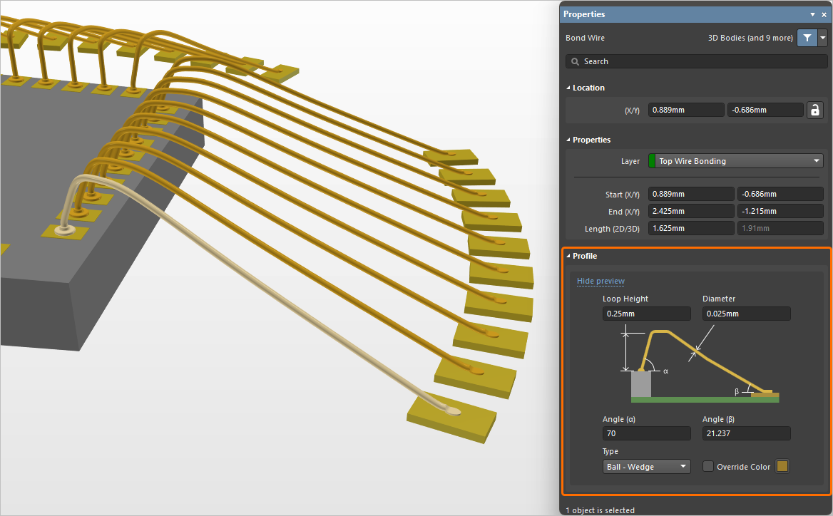
Additional editing controls for defining the shape/profile of a bond wire. You can now specify a start Angle (α) and end Angle (β).
The Die Bond Type option has been renamed Type, with a more intuitive selection that reflects the start and end of the bond wire (either Ball - Wedge or Wedge - Wedge). You also have the ability to enable and specify an Override Color for a bond wire. This facilitates being able to distinguish between different bond wire 'tiers' associated with different cycles of a wire bonding machine when generating a wire bonding assembly diagram.
-
The ability to place die pads and bond wires on generic 3D bodies (STEP, SOLIDWORKS Part and Parasolid model formats, as well as extruded 3D bodies). When placed on a generic 3D body, die pads will be automatically placed at the body height under the pad center.
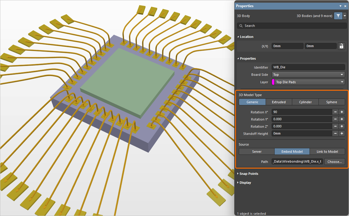
In this example, a Parasolid format model is used as a die. -
The inclusion of bond wire objects in Component Clearance checking, to detect clearance violations between bond wires and other (non bond wire) objects in the 3D space.
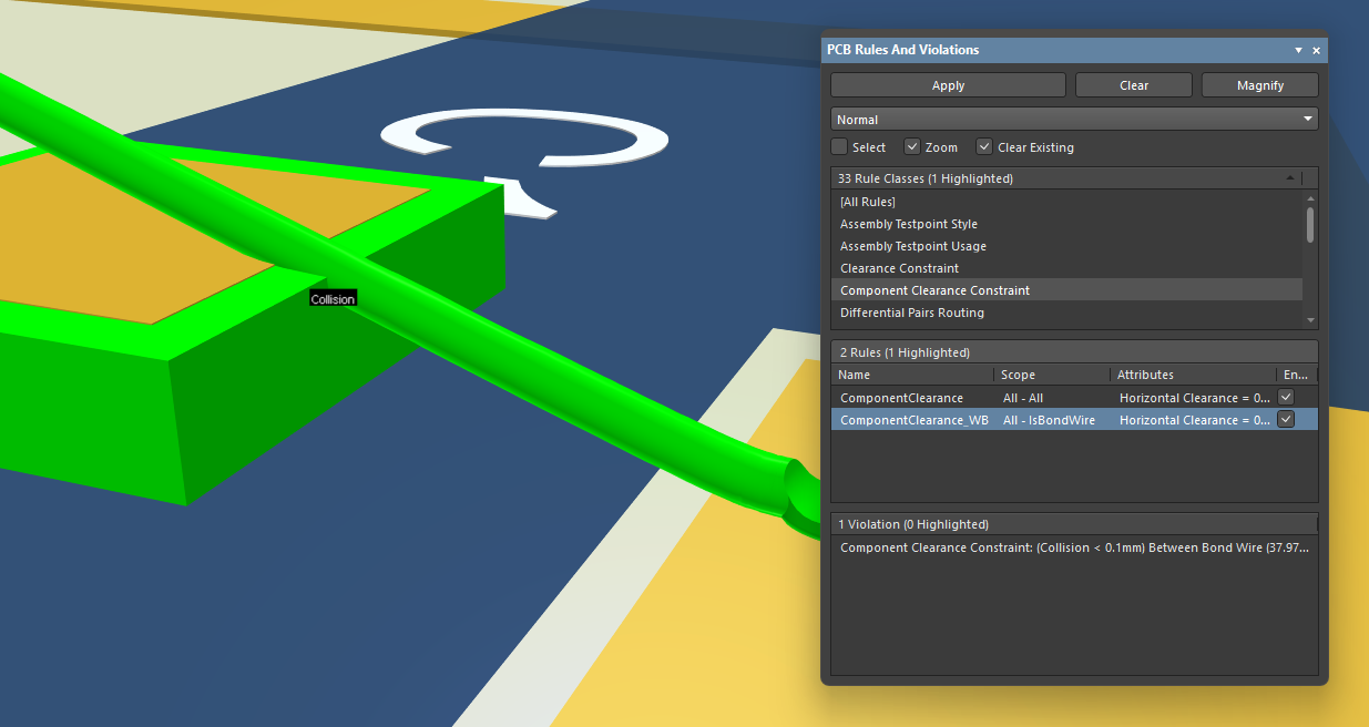
An example of a collision detected between a bond wire and a 3D body. -
Bond wire objects are now included when exporting a PCB to STEP and Parasolid formats.
In addition, colors used for bond wires in the PCB design are now taken into account when placing a board fabrication view, board assembly view and component view into a PCB manufacturing drawing (*.PCBDwf). You can choose to use the layer color or override color (if specified for bond wires on the PCB side).
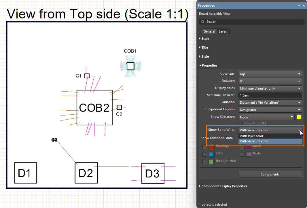
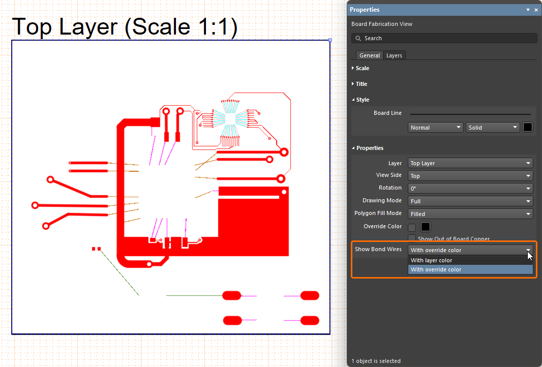
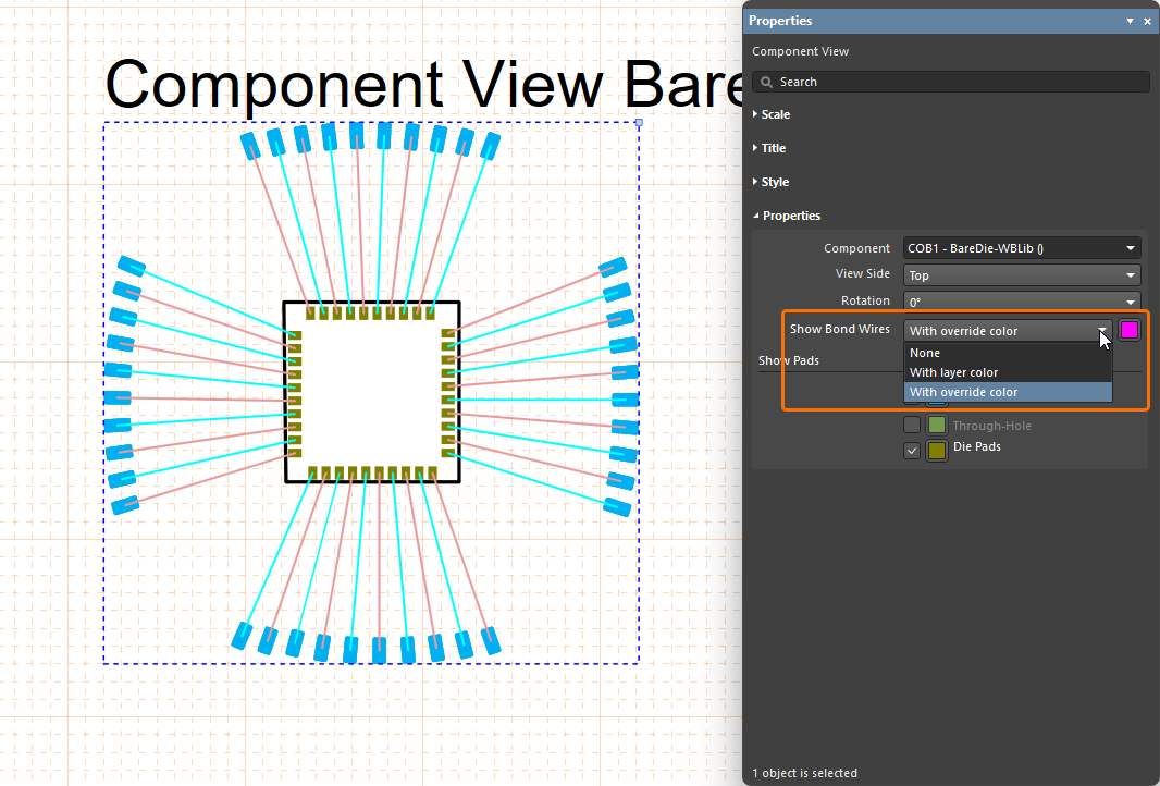
Also, when using the enhanced support for bond wires, the following features are available:
-
Bond Wires is available added as an object to the Selection Filter, accessed from the Active Bar and the Properties panel (pre- and post-selection filtering) –
 .
.
-
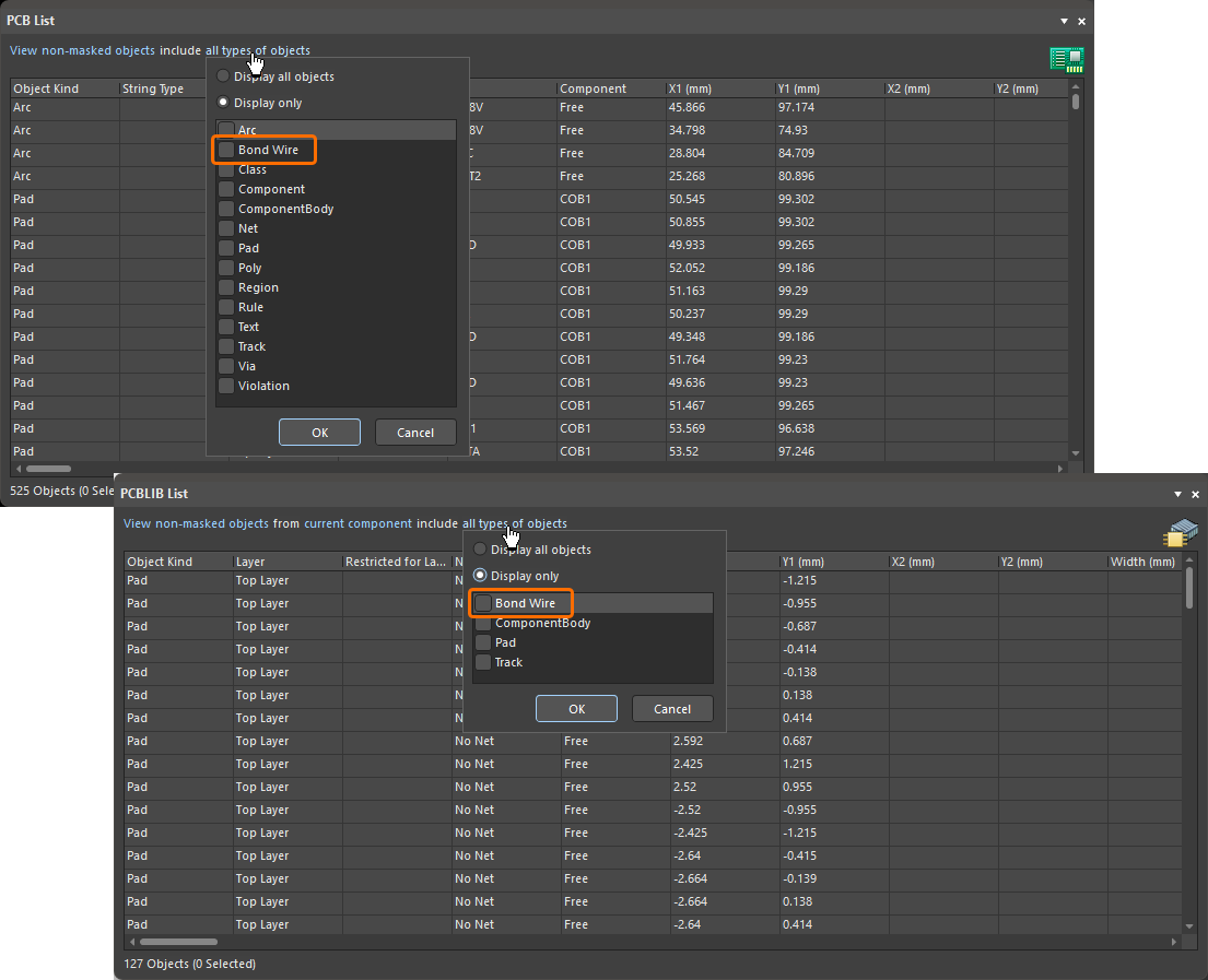
Bond Wire has been added as a distinct object type (when filtering the display of objects) in both PCB List and PCBLIB List panels –
 .
.
-
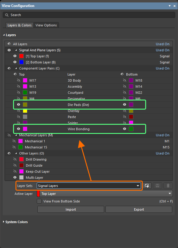
When using Layer Sets, the Die and Wire Bonding layers are now part of the Signal Layers layer set –
 .
.
For more information about wire bonding, refer to the Wire Bonding page.
Data Management Improvements
Enhanced Design Reuse Panel (Open Beta)
This feature gives you the latest, enhanced Design Reuse panel when working with reuse blocks and snippets.
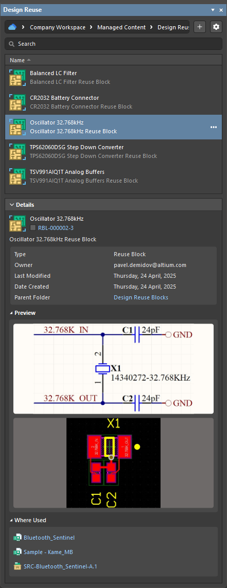
For more information, refer to the Working with Reuse Blocks page.
Enhanced Footprint Model Management in the Item Manager
The Item Manager has been enhanced to address the case where a Workspace component has multiple footprint models defined and the currently assigned model subsequently has its name changed.
A Workspace component can have multiple footprint models assigned. If the currently assigned footprint model subsequently has its name changed and saved back to the Workspace (which creates a new revision of the footprint model) and then the Workspace component itself is saved back to the Workspace (creating a new component revision that uses the new footprint model revision), instances of the component already placed in a design need an update to the latest revision. In this case, the Automatch and Update to latest revision commands of the Item Manager can be used. These features now correctly assign the latest revision of the footprint model whose name has changed.
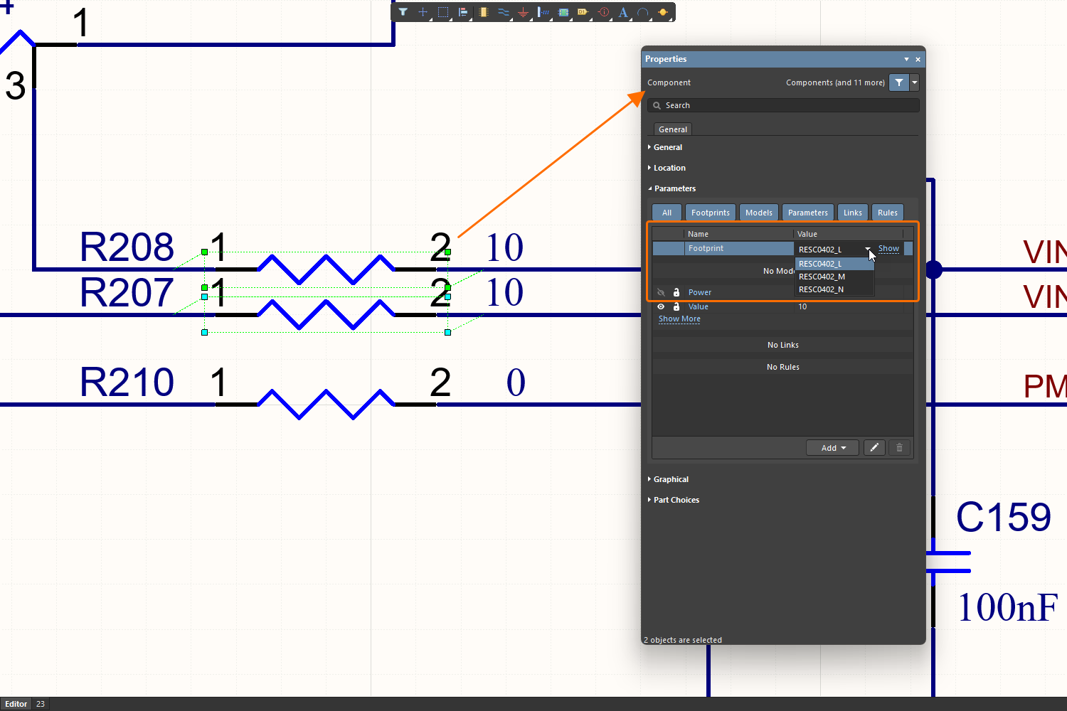
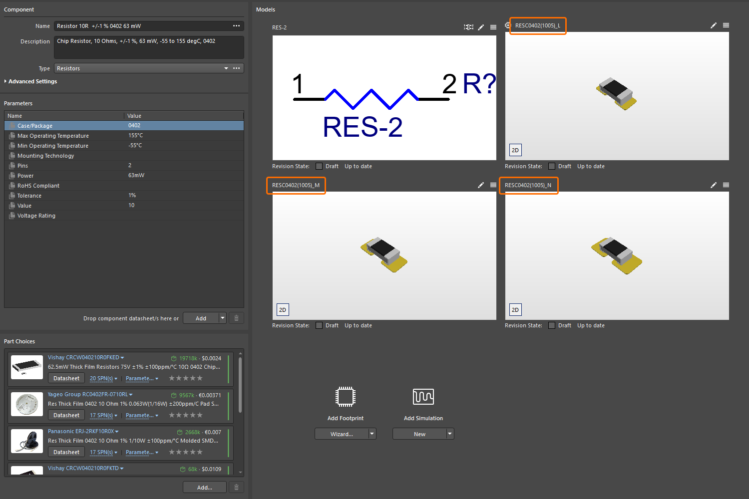
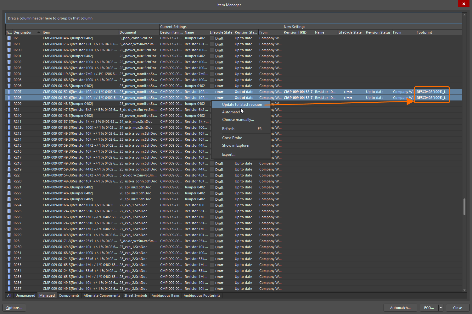
For more information about the Item Manager, refer to the Managing Content with the Item Manager page.
Latest Revision Check in Batch Component Editing
The component rule check Revision that is being edited is not latest is now correctly observed when editing one or more Workspace components using the Component editor in Batch Component Editing mode. This ensures that violations are flagged when editing a component that is not the latest revision available in the Workspace.
In the example shown below, four component revisions are being edited in the Component editor in Batch Component Editing mode. Each revision is not the latest (i.e., later revisions of these components are available in the Workspace), and a violation is flagged for each revision.
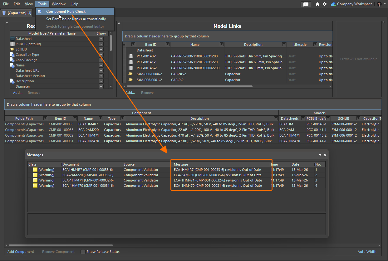
For more information about verifying a component before saving it to a Workspace, refer to the Validating a Component page.
Feature Made Fully Public in Altium Designer 26.5
The following feature is now officially Public with this release:
Additional Feature in Altium Designer 26.5
-
Partial LFS Repository Support: A new advanced settings option –
VCS.AllowLFSRepos– is available in the Advanced Settings dialog with this release which, when enabled, restores previous, partial ability to use LFS repositories when working with Git version control. CAUTION: Altium Designer does not fully support working with LFS repositories and, in some cases, doing so can lead to loss of user data.
Version 26.4
Altium Designer Develop – Released: 19 March 2026 – Version 26.4.1 (build 13)
Altium Designer Agile – Released: 19 March 2026 – Version 26.4.1 (build 25)
Altium Designer – Released: 19 March 2026 – Version 26.4.1 (build 12)
Release Notes for Altium Designer
Key Highlights
PCB Design Improvement
Z-Axis Clearance (Open Beta)
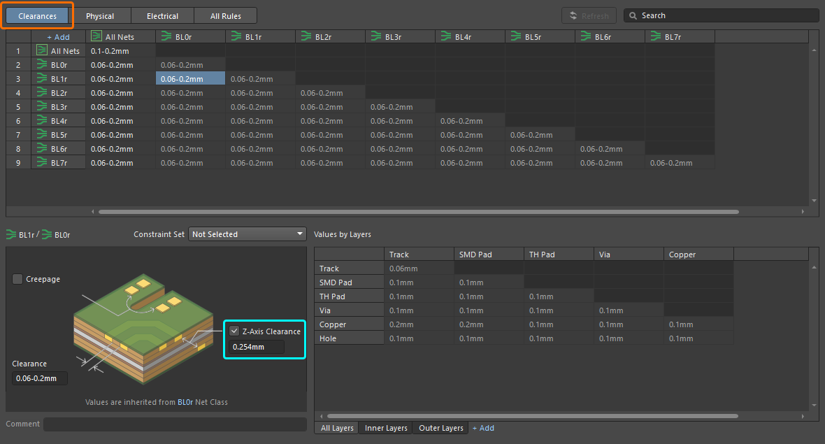
This release adds a new Z-Axis Clearance design rule to both the Constraint Manager and older PCB Rules and Constraints Editor dialog (not accessible in Document View). This rule, part of the Electrical category, can be used to check the minimum clearances between various primitives on different copper layers.
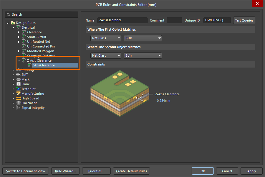
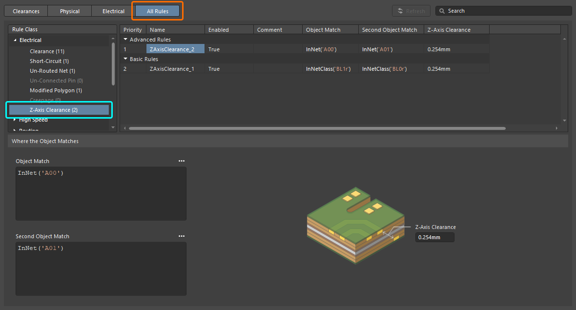
In the Constraint Manager, the Z-Axis Clearance constraint can be specified when defining electrical clearances between classes of nets and/or differential pairs (from the Clearances view) and also by adding a new advanced rule of this type (from the All Rules view, when the Constraint Manager is accessed from the PCB).
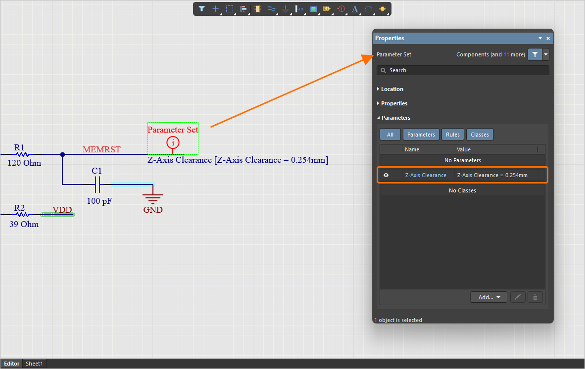
You can also add a rule of this type to a parameter set directive when placed on a schematic.
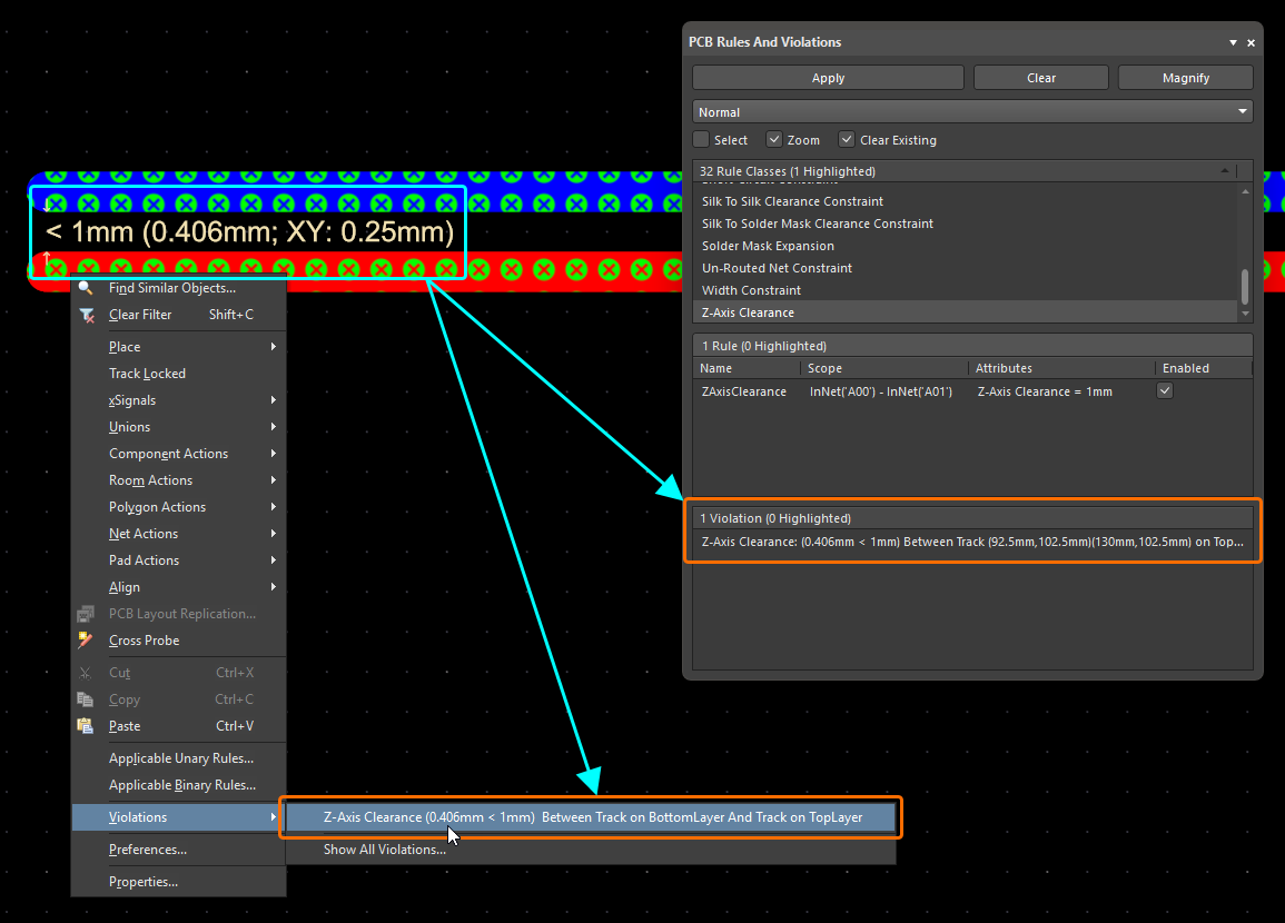
The new rule is supported by both Online and Batch DRC (enabled by default for Batch DRC) and the associated violation mechanisms (details/overlay – both disabled by default also). With display of Violation Details enabled for the rule (PCB Editor – DRC Violations Display page of the Preferences dialog), text in the PCB design space is presented in the format:
< [RuleValue] ([Actual Z-Axis Clearance Value]; XY: [Z-Axis Clearance Projected on XY])
Where the [RuleValue] is the constraint specified in the rule and the [Actual Z-Axis Clearance Value] is the shortest distance, diagonally, between edges of primitives on different layers.
In other places within the software, the following format is used:
Z-Axis Clearance: ([Actual Z-Axis Clearance Value] < [RuleValue]) Between [Object1Description] And [Object2Description]
The new rule is also supported by:
-
Polygon pours (solid and hatched) and internal planes
-
The PCB CoDesign feature
For more information, refer to the Electrical Rule Types page.
Constraint Manager Improvement
Added Min, Max and Preferred Values for Diameter and Hole Size
You now can specify separate minimum (Min), maximum (Max) and preferred (Preferred) values for Diameter and Hole Size when defining a Routing Via Style rule in the Physical view, in addition to the template-preferred definition. This allows for more specific constraints to be defined.
In addition, when accessing the Constraint Manager from the PCB or when configuring constraints for a specific layer stack, you can now switch between the Min/Max Preferred expanded view and the Templates view by choosing the desired tab.
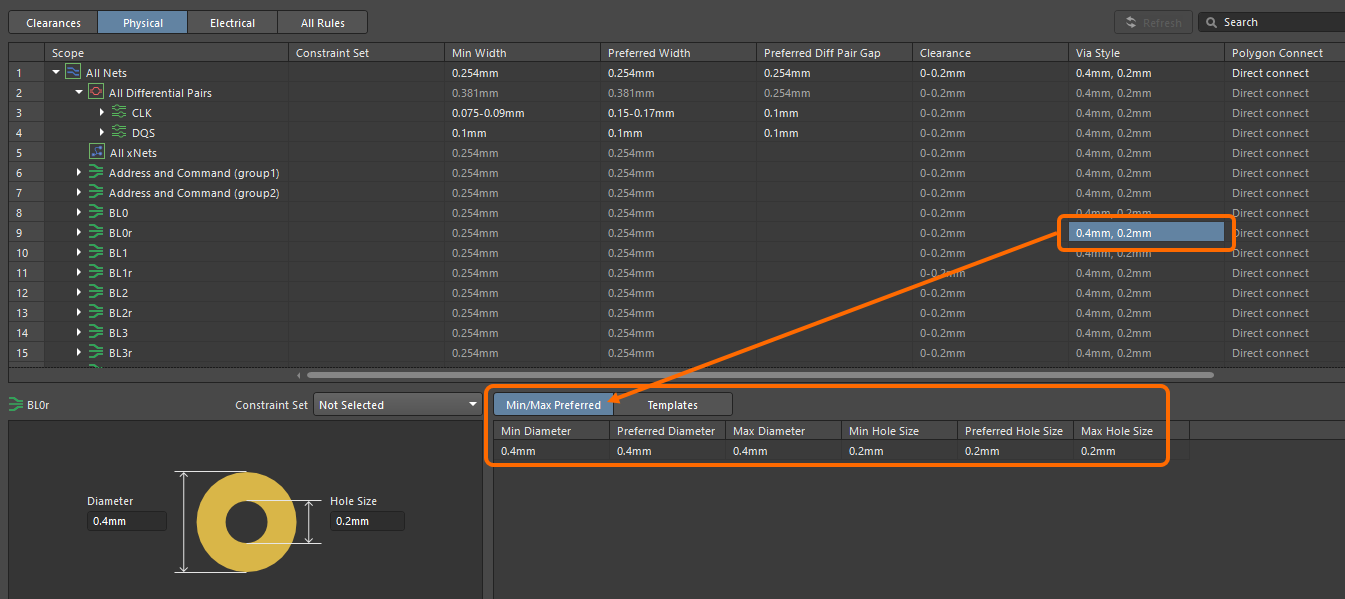
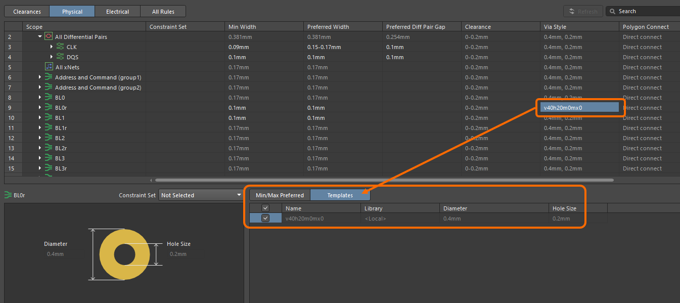
For more information, refer to the Defining Design Requirements Using the Constraint Manager page.
Data Management Improvements
Supplier Data Merging (Open Beta)
This release brings a key enhancement when using the Altium Designer Custom Parts Provider Synchronization feature (learn more) to map supplier data from a specified database source to Workspace supply chain data.
Supplier data from your configured Custom Parts Provider is now merged with the Altium Parts Provider to present all supplier information combined, wherever supplier data (SPNs) is presented in the software UI, including the Manufacturer Part Search panel, ActiveBOM, and whenever adding part choices.
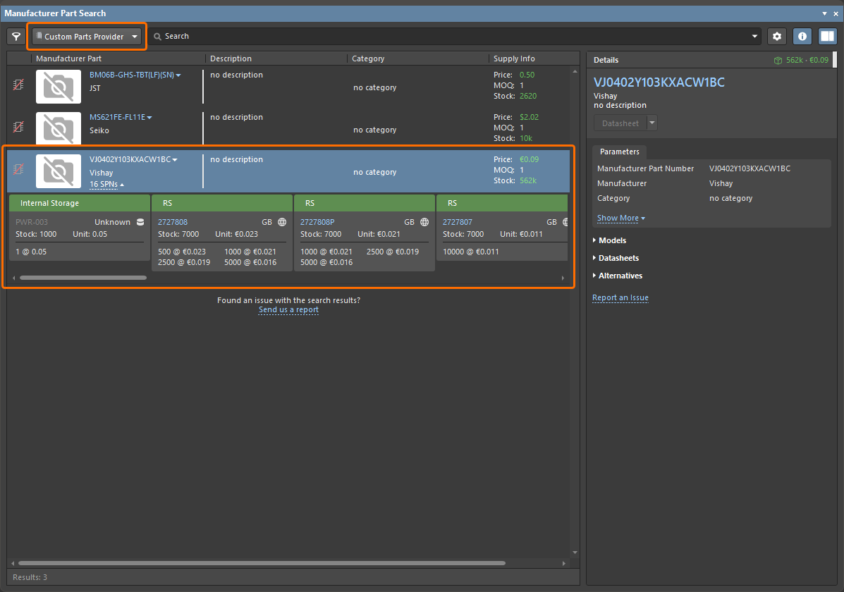
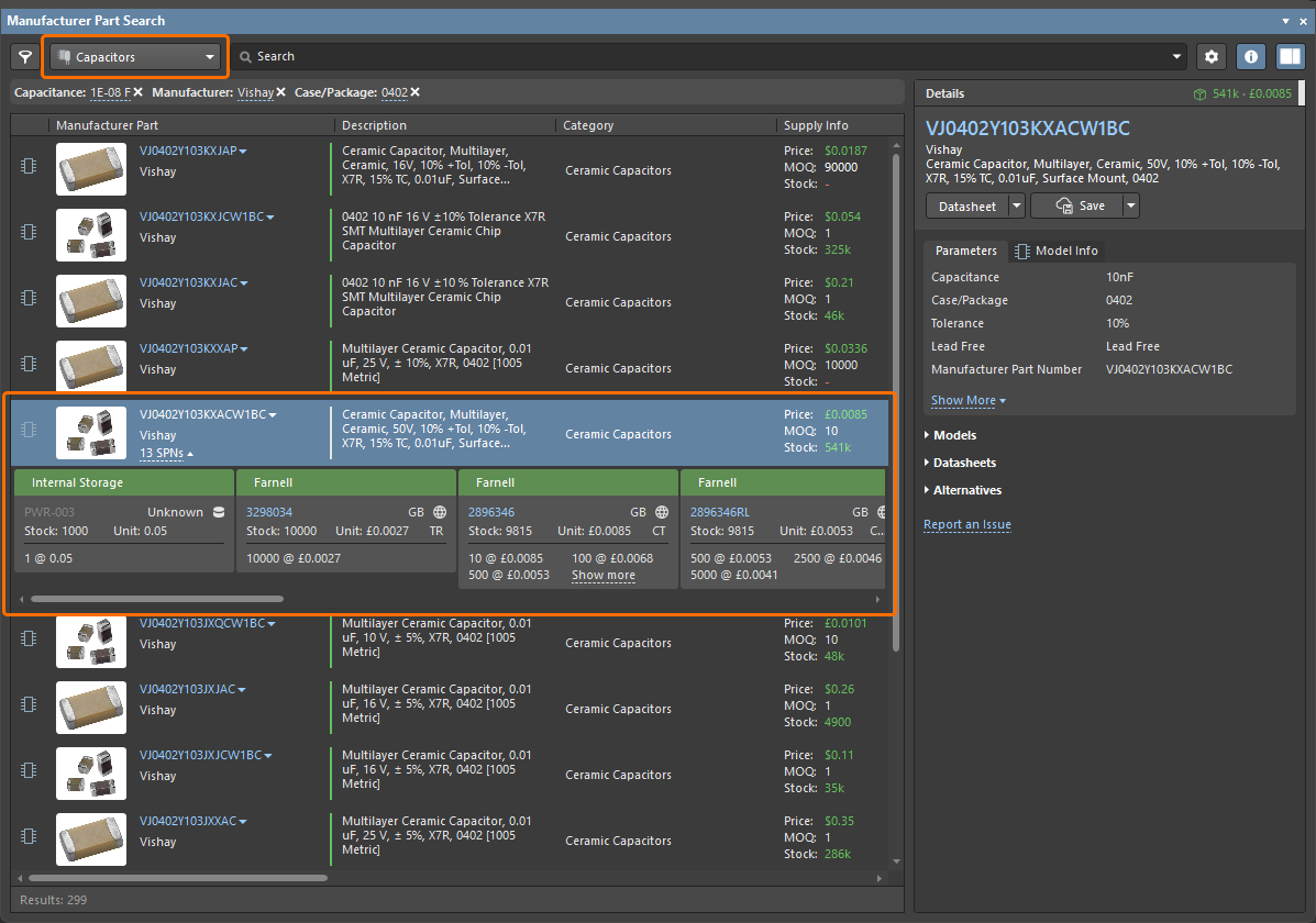
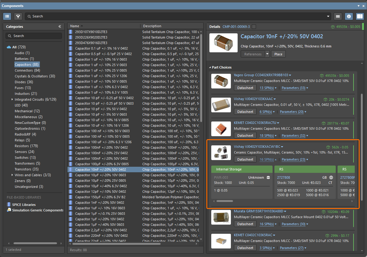
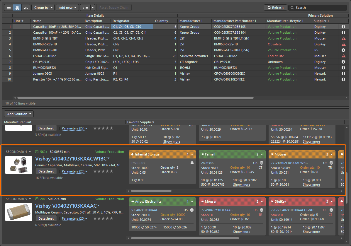
For more information about synchronizing a supply chain database to Workspace data, refer to the Supply Chain Database to Workspace Data Synchronization page.
Ability to Change the Lifecycle State from ActiveBOM
You now have the ability to change the lifecycle state of selected component(s) directly from within an ActiveBOM document (*.BomDoc). A new Change State command can be found on the ActiveBOM’s right-click Operations sub-menu.
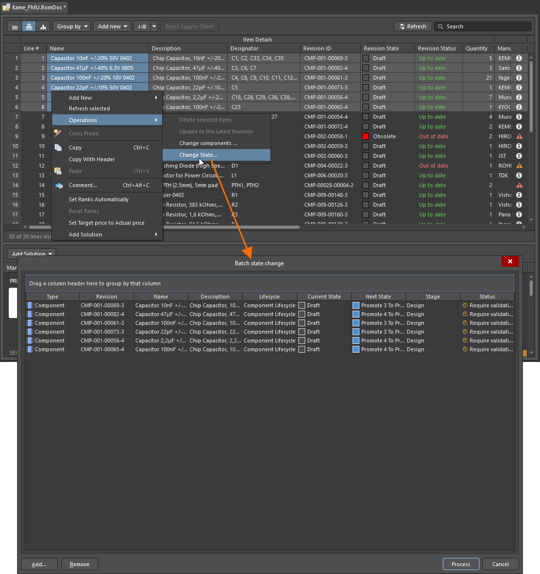
For more information, refer to the Managing Item Revision Lifecycle page.
Advanced Sharing Settings UI Changes
When sharing a live design or design snapshot through the Share dialog, the former dialog accessed from the Advanced Settings control has been redesigned as a pop-up window.
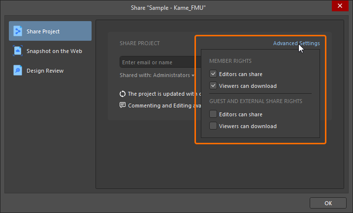
When sharing a live design, share and download options are now gathered by Member Rights (for Workspace members) and Guest and External Share Rights (for external guest users with whom projects have been shared). Confirmation of changes is made by clicking a dedicated  button back in the main Share dialog.
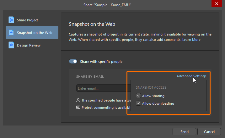
For more information about design sharing, refer to the Sharing a Design page.
Enhanced 'Create Tag' Command
The Create Tag command has been restored on the History & Version Control sub-menu. The command also has been enhanced when entering a value for the tag. If an invalid character is used, the  icon appears in the Create Tag dialog. Hover over the icon to view a 'hint' of which characters are allowed, i.e. letters, numbers, dot ('.'), dash ('-'), number sign ('#') and underscore ('_'); update the tag as necessary.
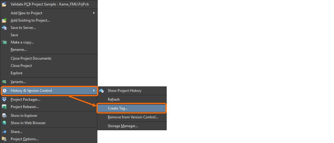
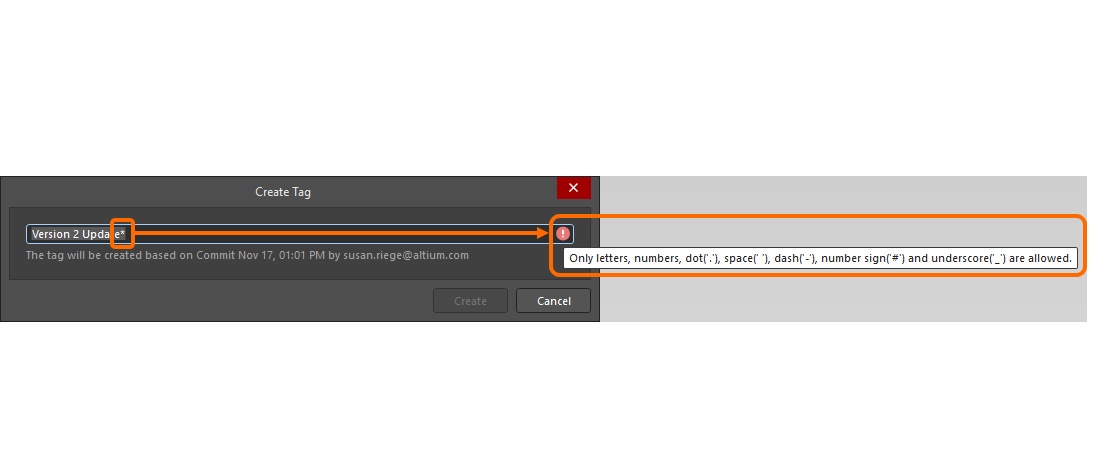
For more information, refer to the Browsing the History of a Project page.
Support PostgreSQL Databases in Synchronization Features
Altium Designer's Custom Parts Provider Synchronization and Components Synchronization features have been improved to now support PostgreSQL databases.
For more information about synchronization features, refer to the Component Database to Workspace Data Synchronization and Supply Chain Database to Workspace Data Synchronization pages.
BOM CoDesign Improvement
Enhanced 'Explore Suggested Component' Command
When using the BOM CoDesign feature and in particular the Explore Suggested Component command (from the Differences section of the Properties panel), if the suggested component is not the latest revision, that specific revision will now be opened in the Components panel.
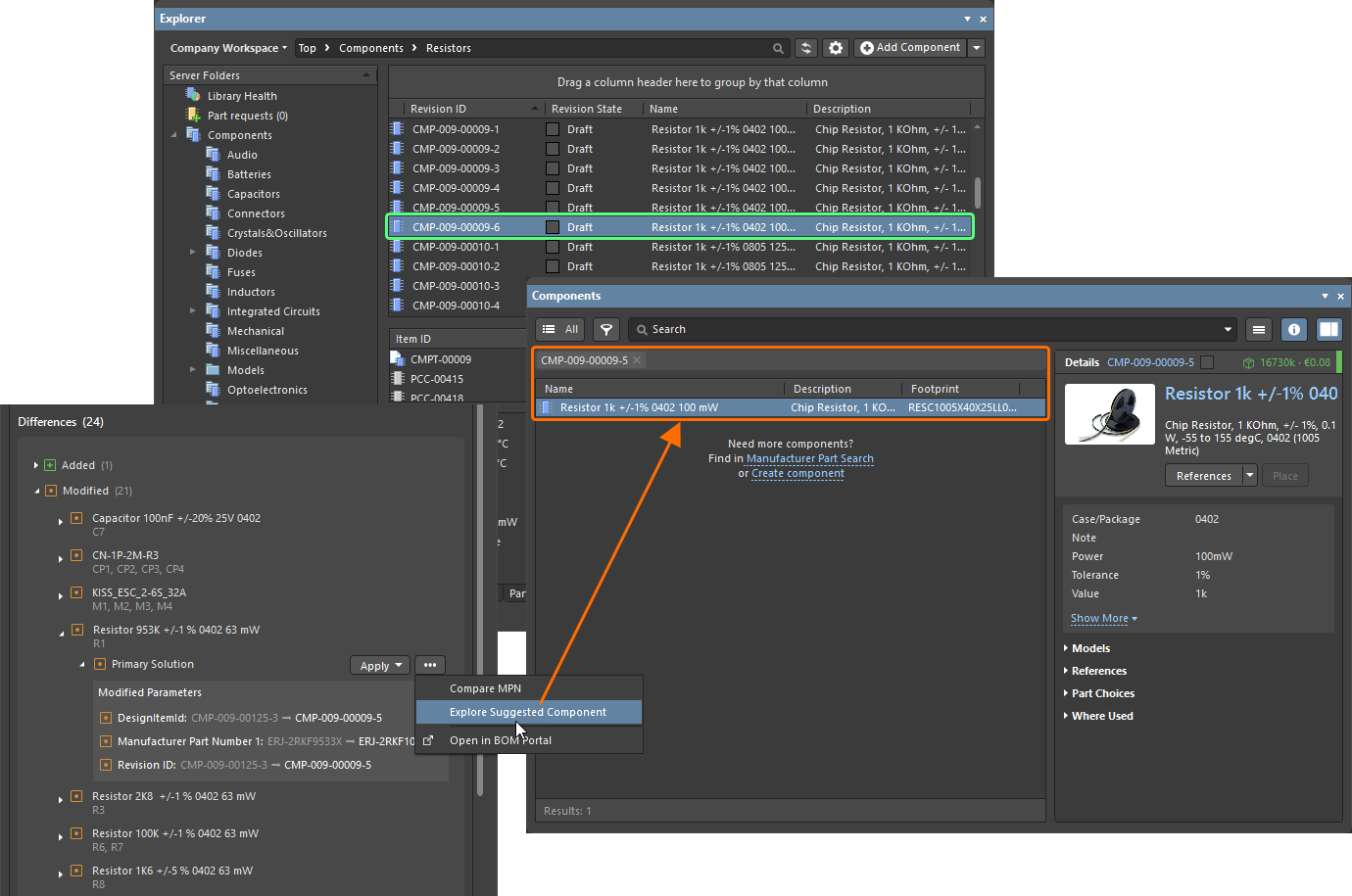
While the suggested component revision CMP-009-00009-5 is not the latest (revision CMP-009-00009-6 of the same component exists in the library), the Explore Suggested Component command now opens the suggested revision in the Components panel.
For more information about the BOM CoDesign feature, refer to the BOM CoDesign page.
Feature Made Fully Public in Altium Designer 26.4
The following feature is now officially Public with this release:
Additional Features in Altium Designer 26.4
-
The Open CASCADE library for Multi-board Assembly Documents (Open Beta): A new advanced settings option –
System.MBAEngine.UseOpenCascade– is available in the Advanced Settings dialog with this release that switches from using the C3D library for geometric modeling of a multi-board assembly document (*.MbaDoc) to using the Open CASCADE library when enabled. Note that when opening an older multi-board assembly document (from a previous version of the software) in this release with the option enabled, created mates will be removed. You can choose between keeping relative positions of assembly parts or placing them in a line. You will have the option to create a backup of the older version at the time of opening. -
JSON Web Token (Open Beta): A new advanced settings option –
EDMS.CloudLoginByJWT– is available in the Advanced Settings dialog with this release which, when enabled, uses a JWT (JSON Web Token) for user identification and authentication when connecting from Altium Designer to a Workspace on the Altium Platform.
Version 26.3
Altium Designer Develop – Released: 5 February 2026 – Version 26.3.0 (build 5)
Altium Designer Agile – Released: 5 February 2026 – Version 26.3.0 (build 18)
Altium Designer – Released: 5 February 2026 – Version 26.3.0 (build 6)
Release Notes for Altium Designer
Key Highlights
PCB Design Improvement
Enhanced Support for SOLIDWORKS and Parasolid Formats
-
Support has been added for SOLIDWORKS 2024 and 2025 models (
*.SldPrt) when working with 3D bodies. -
Exporting a PCB into Parasolid file format (
*.x_t) now uses Parasolid version 35.1. This enables later versions of SOLIDWORKS (2024 and 2025) to correctly open/import the file.
For more information, refer to the Mechanical Data Import-Export Support page.
Harness Design Improvements
Displaying Jumper Wires
Jumper wires defined in a wiring diagram are now correctly accommodated in the associated layout drawing. A jumper wire connects two cavities of the same connector. With a bundle selected in the layout drawing, the Bundle Objects region of the Properties panel will now include such jumper wires that start and end at the same connection point as part of that bundle.
Such wires will only have the option to define their length manually. The entered value will then be included in the harness project's ActiveBOM document and manufacturing drawing (BOM table and wiring list).
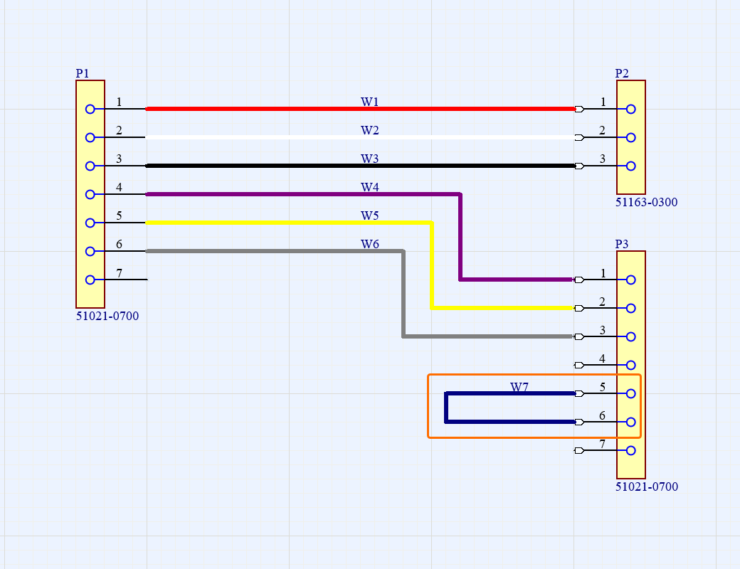
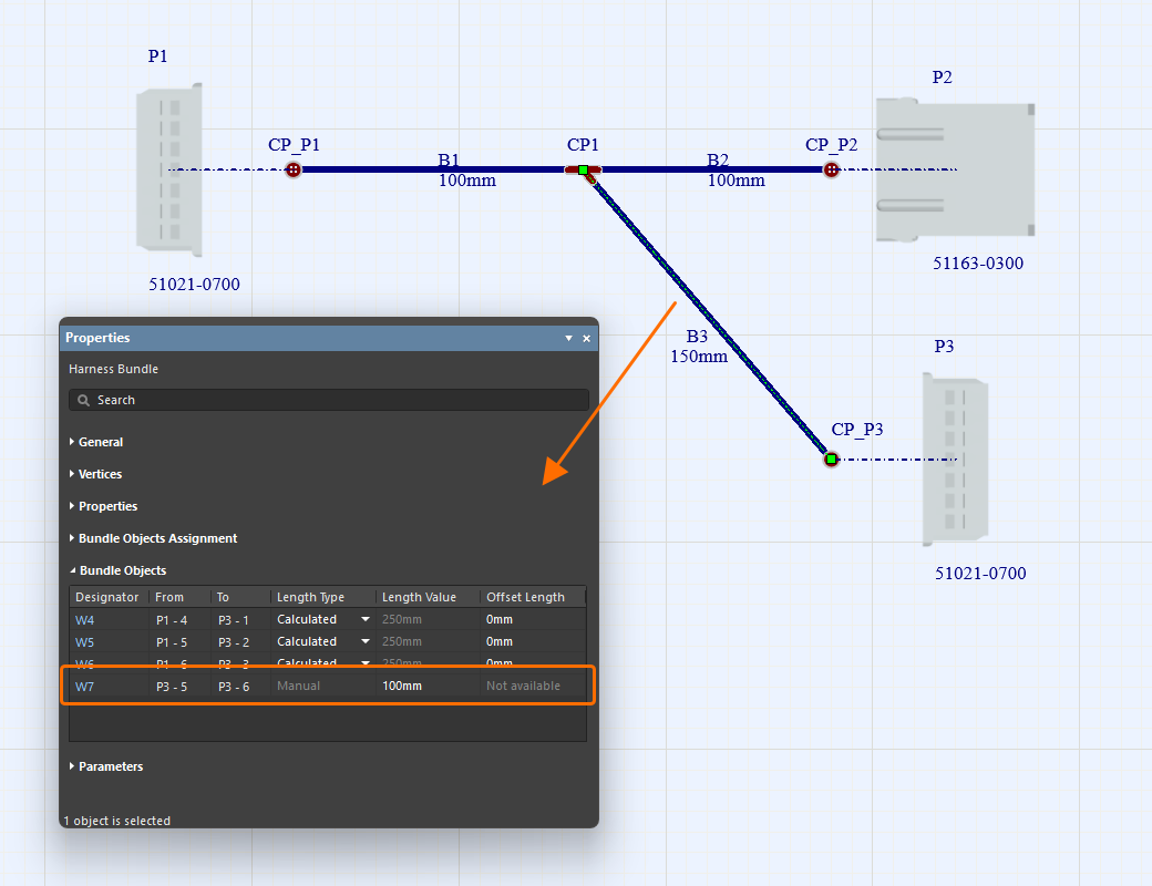
For more information, refer to the Creating the Layout Drawing page.
Improved 'Update From Libraries' Feature
Updating from libraries (Tools » Update From Libraries) has been improved for wiring diagrams (*.WirDoc) and layout drawings (*.LdrDoc) of harness designs.
-
When the feature is accessed from a wiring diagram, wires, cavity components, and associated parts are now also included.
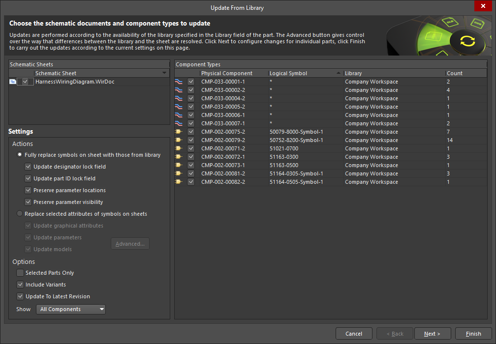
-
When the feature is accessed from a layout drawing, harness coverings, layout labels, and associated parts are now also included.
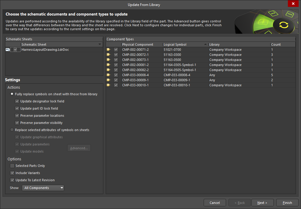
For more information, refer to the Defining the Wiring Diagram and Creating the Layout Drawing pages.
Platform Improvement
Master Services Agreement Replaces EULA
The End User License Agreement (EULA) has been replaced with the Master Services Agreement (MSA) when installing Altium Designer Develop or Altium Designer Agile.
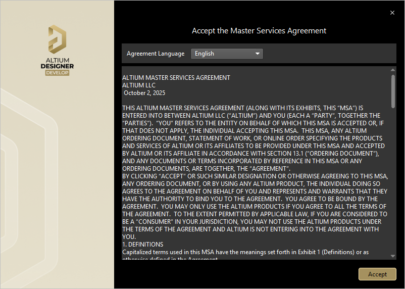
For more information, refer to the Installing & Managing Altium Designer Develop and Installing & Managing Altium Designer Agile pages.
Version 26.2
Altium Designer Develop – Released: 8 January 2026 – Version 26.2.0 (build 10)
Altium Designer Agile – Released: 8 January 2026 – Version 26.2.0 (build 28)
Altium Designer – Released: 8 January 2026 – Version 26.2.0 (build 7)
Release Notes for Altium Designer
Key Highlights
Wire Bonding Improvements
Support for Panelized PCBs
Bond wires and die pads are now displayed when viewing a panelized PCB document in 3D.
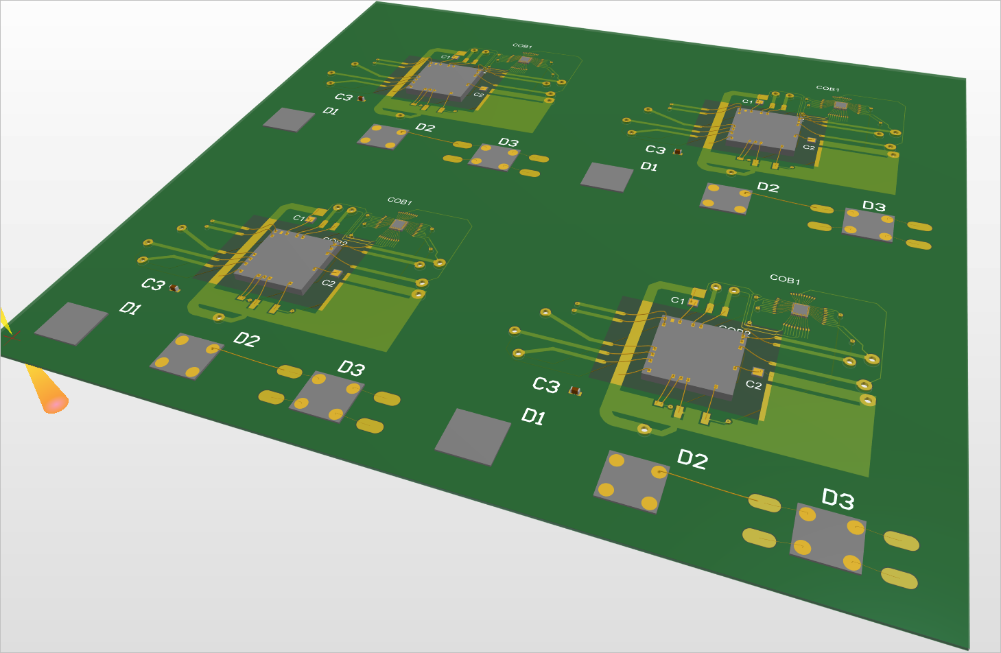
Also, generation of a Wire Bonding Table Report from a panelized PCB document is now supported.
For more information about panelized PCBs, refer to the Board Panelization page.
A New Query Keyword for Detecting Bond Wires
A new IsBondwire query keyword (PCB Object Type Check) is available, when constructing logical query expressions to use in the filtering of objects in a PCB/PcbLib or in the scoping of a design rule.

For more information, refer to the Object Type Checks page.
Harness Design Improvement
Ability to Place a Harness Bundle Break Point
A break point, which is used as an indication that the bundle is Not to Scale (NTS), can now be placed on a harness bundle in the harness layout drawing (*.LdrDoc). The bundle will display a break symbol in the middle of its longest segment as shown in the first image below, and the properties will display the Drawn Length, which reflects the length of the bundle as drawn in the design space. Typically, the physical bundle length will be considerably larger. When the Length field (actual physical length) is set and it differs from the drawn length, the bundle will display a break symbol at the center of its longest segment to indicate that the bundle is Not to Scale (NTS). To place a break, enable the Add Break Symbol option in the Properties region of the bundle properties. Harness coverings that cover a harness bundle with a break point will also display the break in the same location. If the harness covering ends at the harness bundle break point, the covering will be drawn slightly longer, as shown in the second image.
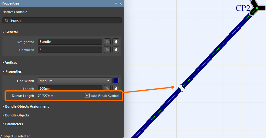
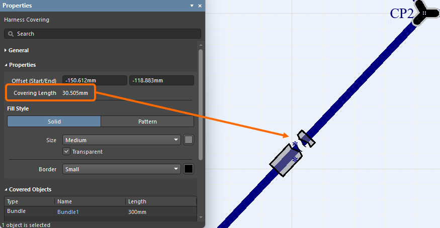
For more information, refer to the Creating the Harness Layout Drawing page.
Data Management Improvement
Ability to Preserve Lifecycle State When Synchronizing Components
With this release, you now have the ability to preserve the lifecycle state when performing component synchronization between your Workspace and your component database using Altium Designer’s Components Synchronization feature.
This ability is facilitated by a new Preserve lifecycle state option. With the data source (table) selected in the Components Synchronization Configuration document (*.CmpSync), this option can be found in the Advanced section of the Properties panel.
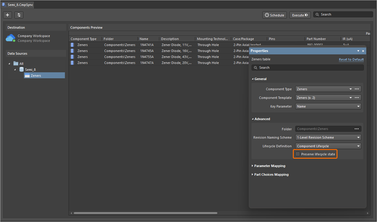
Note that this ability is available for those who are assigned Allow to skip lifecycle state change for new revisions operational permission (learn more about Setting Global Operation Permissions for a Workspace).
For more information about the Components Synchronization feature, refer to the Component Database to Workspace Data Synchronization page.
Features Made Fully Public in Altium Designer 26.2
The following features are now officially Public with this release:
-
BOM CoDesign - available since 25.1
-
Excluding Supplier-related Fields from BOM Comparison Result - available since 26.1
Version 26.1
Altium Designer Develop – Released: 3 December 2025 – Version 26.1.0 (build 6)
Altium Designer Agile – Released: 3 December 2025 – Version 26.1.0 (build 13)
Altium Designer – Released: 3 December 2025 – Version 26.1.0 (build 7)
Release Notes for Altium Designer
Key Highlights
PCB Design Improvement
Solder Mask Expansion Rule Default Now 0 Mils (Open Beta)
Observing the IPC-7351B standard in relation to padstack defaults, where the solder mask openings are typically a 1:1 ratio of the land size, the values for the Solder Mask Expansion rule (in PCB documents) and rule-driven solder mask expansion (in PCB library documents) are now set to 0 mil by default (previously 4 mil).
For a PCB library (*.PcbLib), support for these new default values are at the library level, inherited by all component footprints created therein. The same PCBlib will show, for all object rule-driven solder mask expansion, 4 mils expansion when opened in a previous version of Altium Designer and 0 mils expansion when opened in this release and later, as shown below for a pad object.
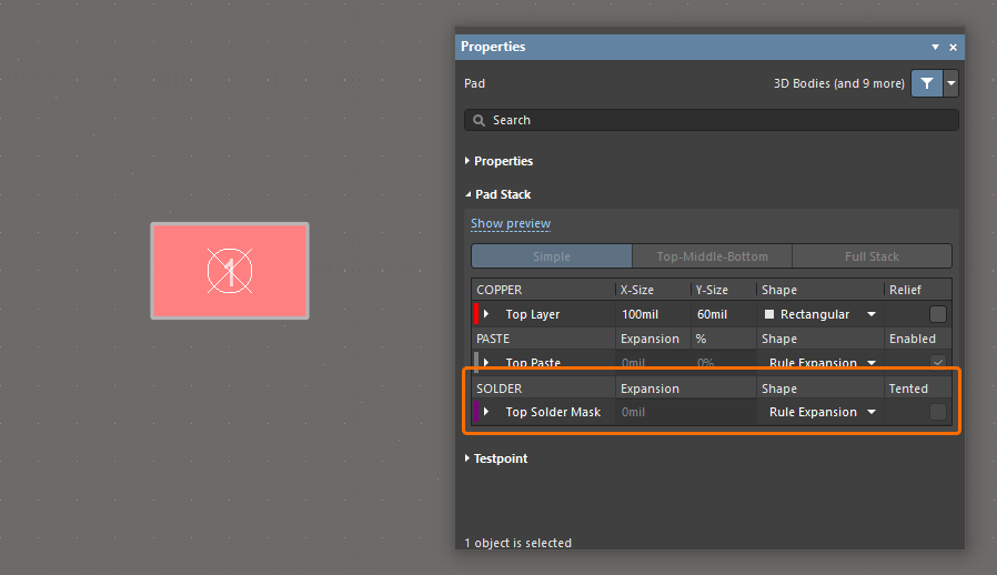
For a PCB document (*.PcbDoc), all existing Solder Mask Expansion rules store their initial values. The default values used for any newly created rule are determined by the version of Altium Designer where that rule was created and will not change while opening in another version of Altium Designer. Therefore, the default is 4 mils expansion when created in a previous version of Altium Designer and opened in any other version, and 0 mils expansion when created in this release (or later) and opened in any other version, as shown below.
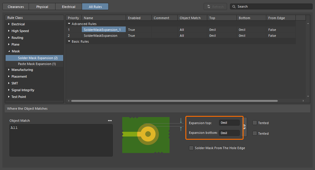
A newly created Solder Mask Expansion design rule in the Constraint Manager.
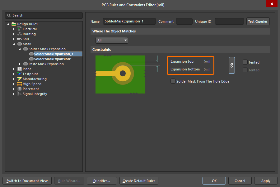
A newly created Solder Mask Expansion design rule in the PCB Rules and Constraints Editor dialog.
For more information about the Solder Mask Expansion design rule, refer to the Mask Rule Types page.
Constraint Manager Improvement
Added Ability to Filter Classes
An ability to filter classes has been implemented in the Constraint Manager's Clearances view to leverage your work with a large number of classes. This enables the construction of filters (or groupings) of classes to allow switching between, and working with, focused sub-sets of the clearances matrix.
Use the  button at the top right of the Clearances view to access a pop-up from where you can create, edit, remove, and enable/disable filters.
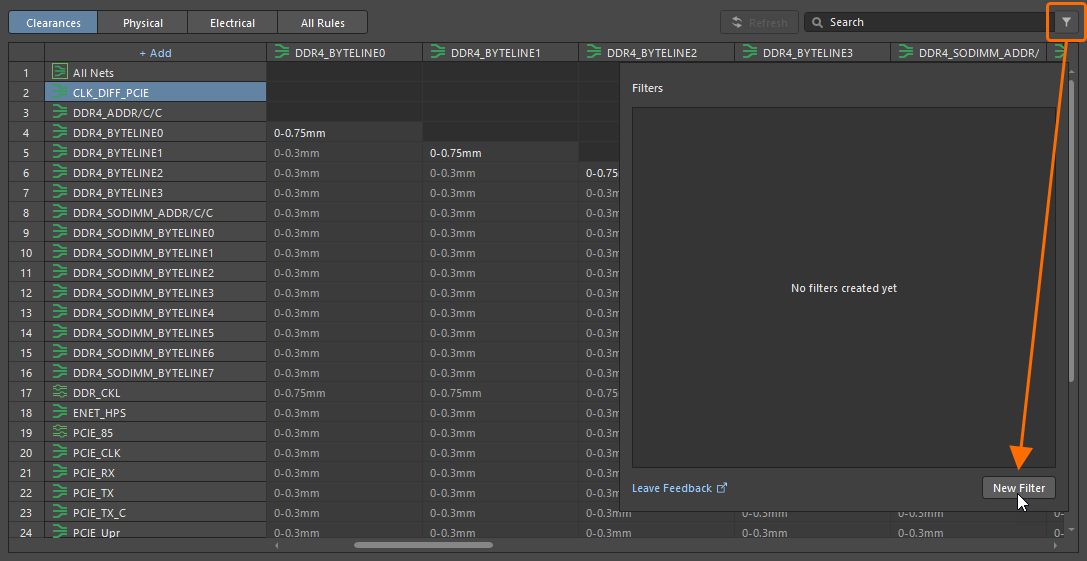
To create a new filter, click the button and then click the  button in the pop-up that appears.
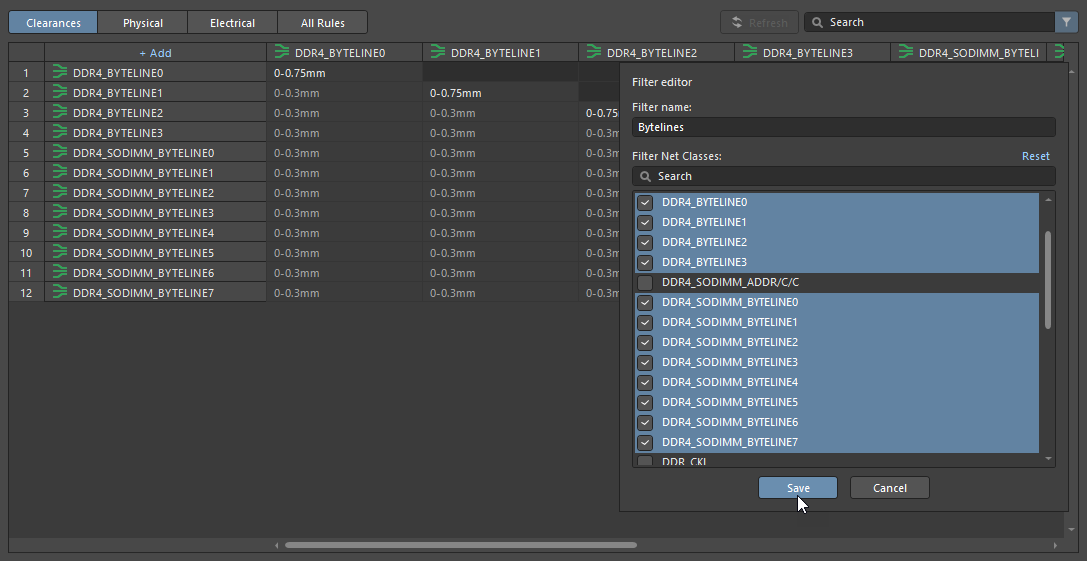
Define a unique name for the new filter, enable the required group of classes, and click  .
.
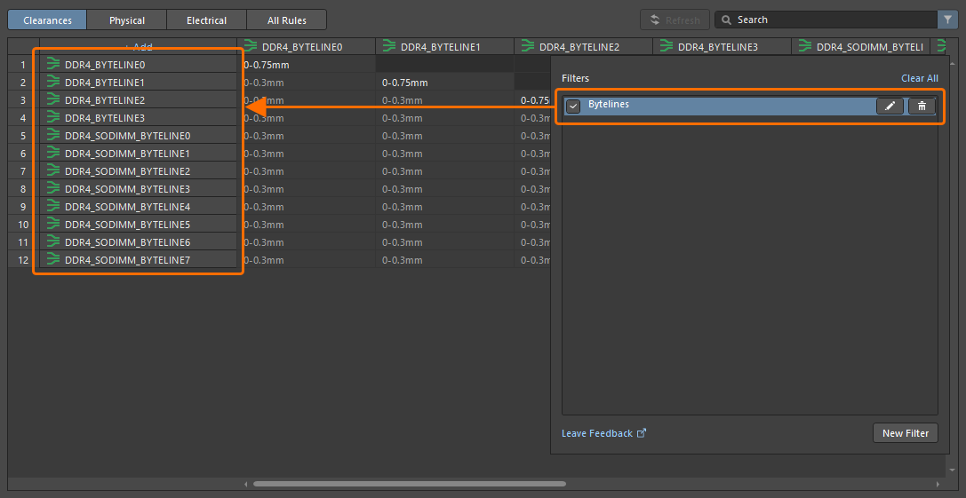
With a filter created, use the available controls in the pop-up to enable, disable, edit, or remove it as needed. Note that when a filter is enabled, the button at the top right is shown as  .
.
For more information about working with the clearance matrix, refer to the Defining Design Requirements Using the Constraint Manager page.
Draftsman Improvement
Enhanced DXF Import to Draftsman Documents (Open Beta)
This feature adds support for importing DXF files version R12 and later into manufacturing drawing documents (*.PCBDwf, *.HarDwf, *.MbDwf). Importing DXF files including splines is also now supported.
For more information about importing DXF files, refer to the Draftsman Placement & Editing Techniques page.
Wire Bonding Improvement
Bond Wire Primitives in Panels
Bond wires are now presented with the correct type (Bond Wire) in the following places:
-
The Primitives region of the PCB panel, with a selected component in Nets mode
-
The Component Primitives region of the PCB panel, with a selected net in Components mode
-
The PCB Library panel, with a selected footprint.
Selecting a bond wire primitive will select/highlight that bond wire within the design space.
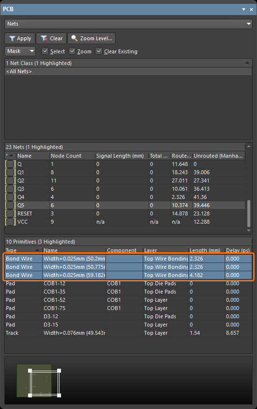
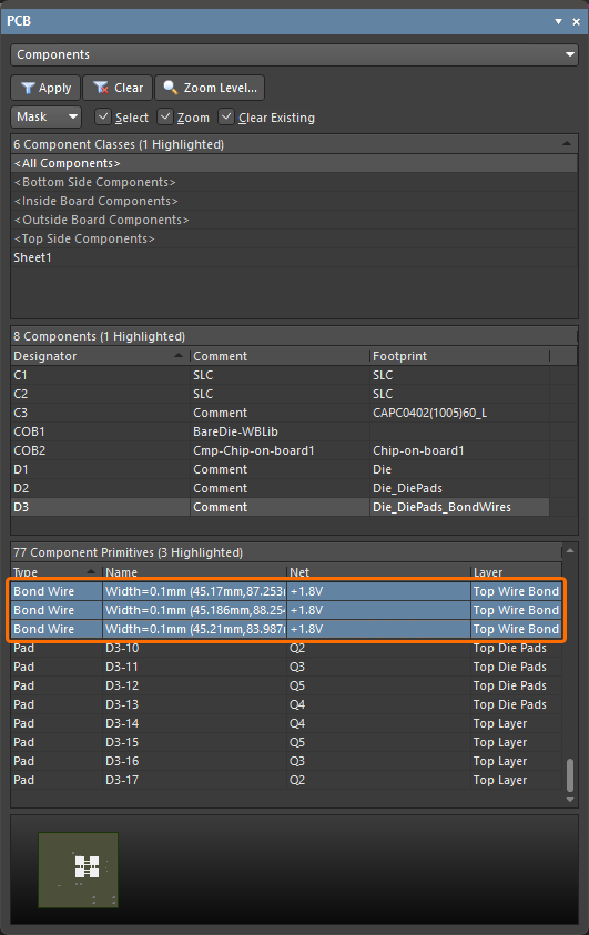
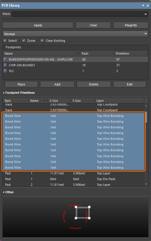
In addition, a corresponding Show Bond Wires option is now available on a region's right-click context menu, for toggling bond wire visibility.
For more information about wire bonding, refer to the Wire Bonding page.
3D-MID Design Improvement
3D-MID Design Rule Check (Open Beta)
This release provides batch Design Rule Checking (DRC) for Width, Clearance, Length and Matched Lengths rule violations, in respect to routed tracks on your 3D substrate. Note that while a generated DRC report will provide information for all of these checks, only clearance violations will be highlighted within the design space.
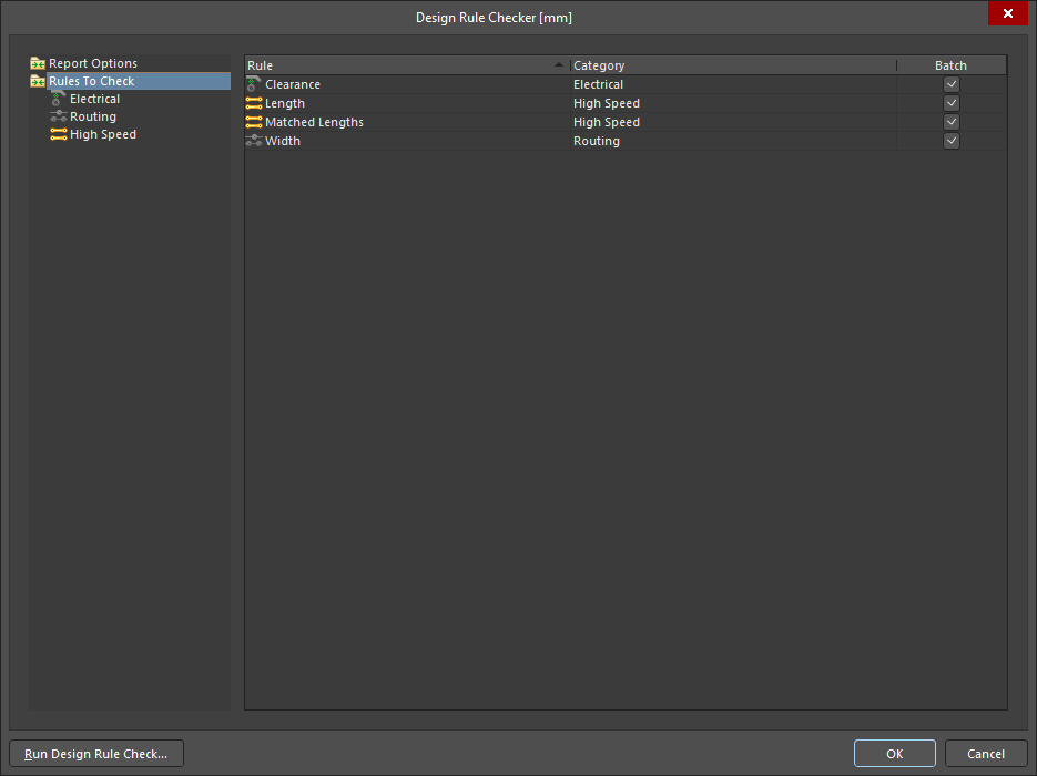
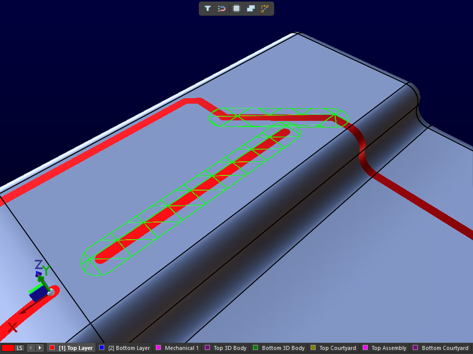
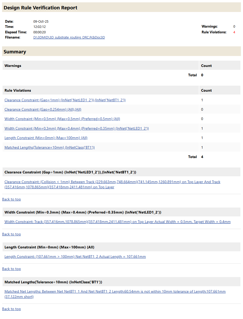
For more information, refer to the 3D-MID Design page.
Multi-board Design Improvement
Ability to Define 'Termination Type' for Harness Entries
The Termination Type for a harness entry can now be defined on a multi-board schematic. The termination types available are:
-
Connector – the standard option used when connecting to a mating connector on the PCB. It typically involves standard board-mounted connectors.
-
Crimps/Ferrules – individual wires are terminated with crimps or ferrules before being inserted into the connector on the PCB side.
-
Wire termination – wires are blunt-cut at the harness end and either screwed down or soldered directly to the PCB. This is common with direct wire-to-board connections such as with some JST connectors.
The information is reflected in the properties for the selected harness entry and the corresponding module entry.
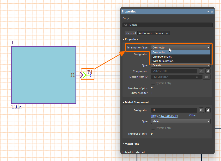
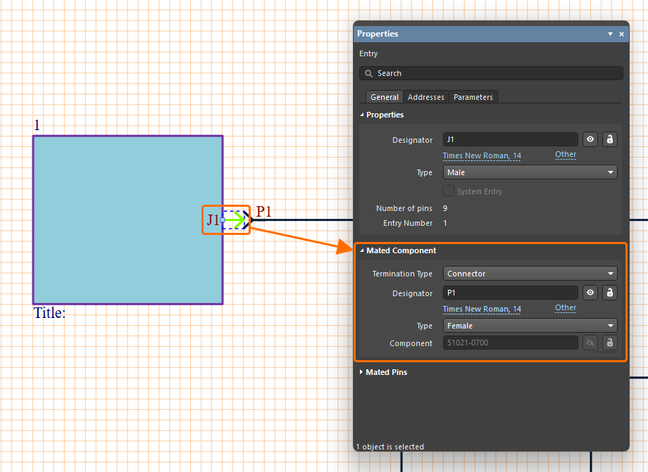
For more information about working with connections on a multi-board schematic, refer to the Working with Connections page.
Harness Design Improvements
Enhanced Synchronization of Wires
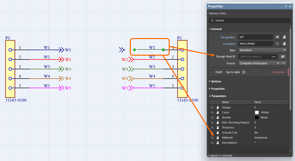
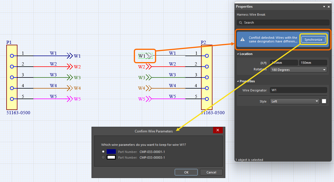
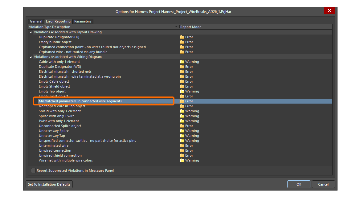
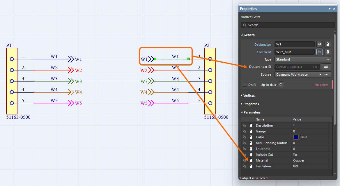
Harness wires connected with a wire break are now recognized even if they have different Design Item IDs. In addition, all wire segments with the same designator connected by the same wire break are now compared (for part number, comment, color, and all parameters). If any differences are found, the Mismatched parameters in connected wire segments violation is reported. A warning also appears in the Properties panel of the wire and wire break signifying that a conflict has been detected between the parameters. Click Synchronize within the warning to open the Conflict Wire Parameters dialog, which gives you the choice of which parameters to use for the wire segment.
Ability to Place a Covering over a Junction Point
You can now apply/extend a harness covering over a junction point (a connection point in the layout drawing where two or more bundles come together) on the harness layout drawing (*.LdrDoc). This removes the need to have separate harness coverings between junction points in a section that contains several connectors.
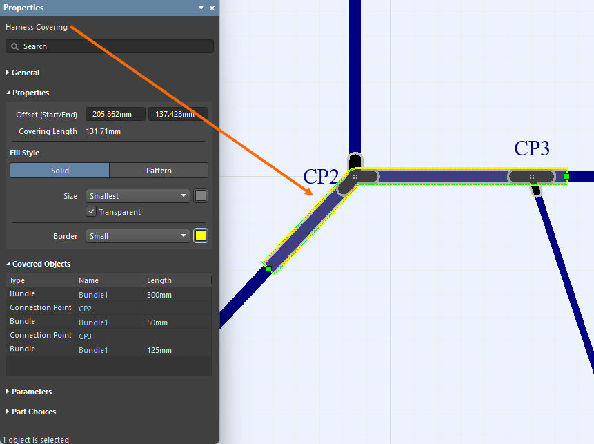
In addition, the start of a covering is now taken as the left-most, top-most point of its path, and that path now includes only the bundles the covering lays on.
For more information, refer to the Creating the Layout Drawing page.
Quantity Field in BOM Changed to 'As Required' for Certain Objects
Wire, cable, and harness coverings are length-based objects and the value is displayed in the Length field. To avoid confusion, the Quantity field for wire, cable and harness covering entries in a Bill Of Materials table and an ActiveBOM document in a manufacturing drawing document (*.HarDwf) is now As Required.
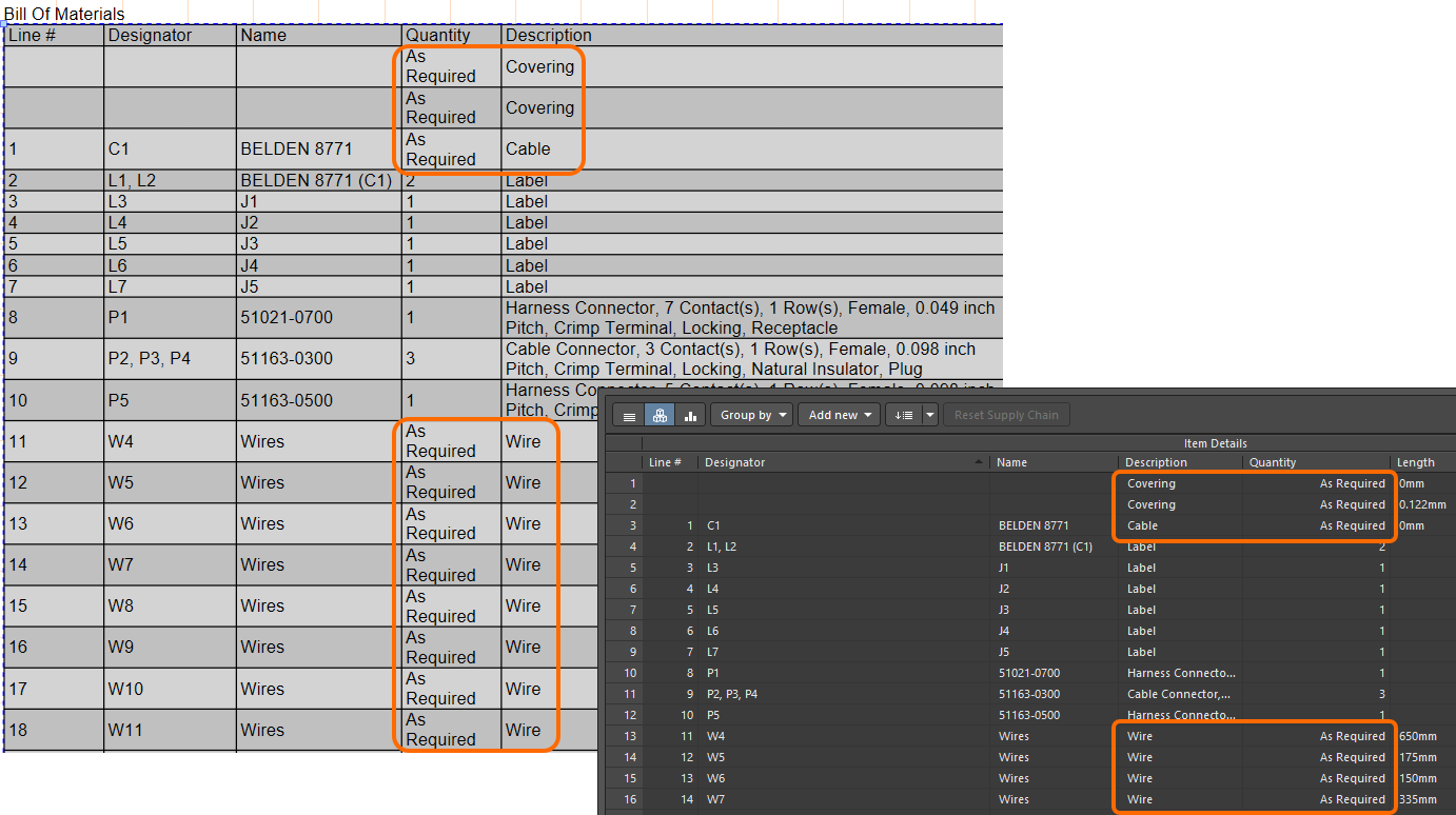
For more information, refer to the Managing Your Bill of Materials (BOM) with ActiveBOM page.
Improved Pin Grouping in Wiring List
Pin grouping in a wiring list that is placed in a harness manufacturing document (*.HarDwf) has been improved. Starting with this release, automatic grouping is applied to the connector with the most wires, and all of its cavities are correctly grouped in the From column of the wiring list as shown in the image below.
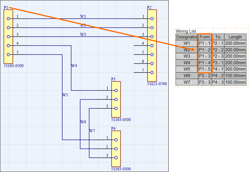
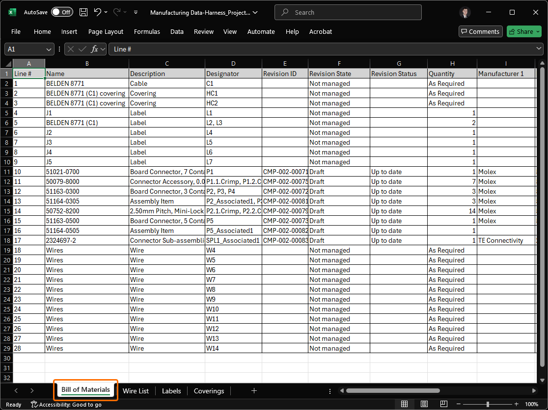
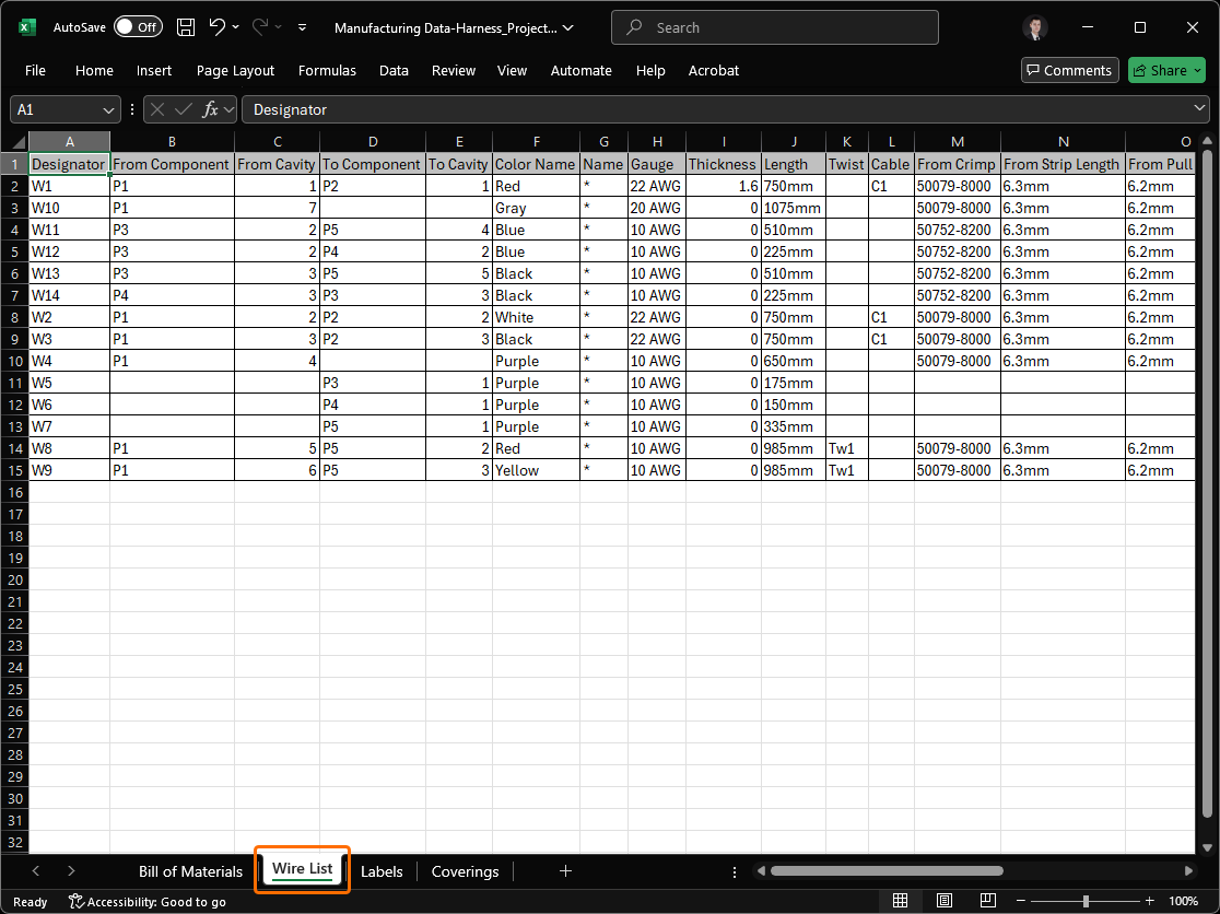
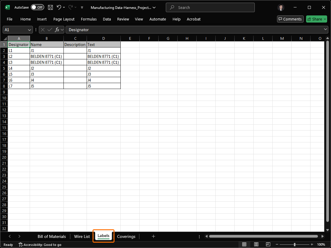
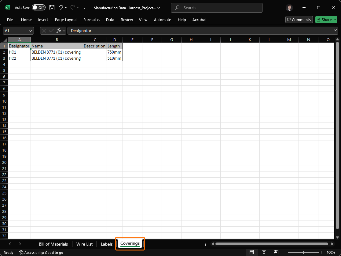
Excel Workbook for Harness Manufacturers
Added the ability to generate, through an Output Job, a single Excel Workbook containing data for use by harness manufacturers. To facilitate this, a new outputter – Manufacturing Data – is available under the Report Outputs section.
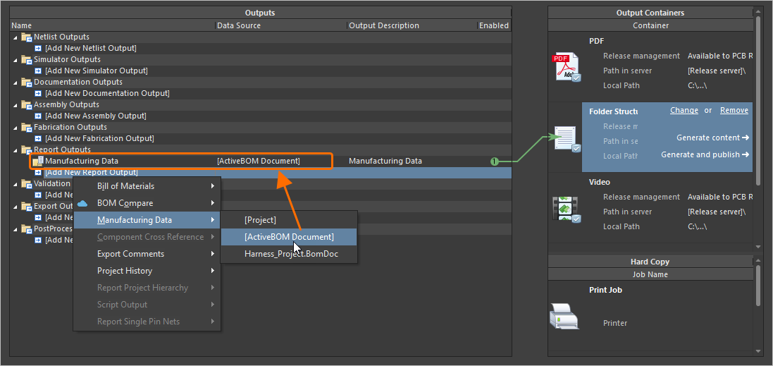
The generated Workbook includes four distinct sheets:
-
Bill of Materials – useful for quick quote generation.
-
Wiring List – for use with wire processing machines.
-
Labels – a summary of the physical labels to be printed for harness bundles, for use with Zebra or other printers.
-
Coverings – a summary of the coverings to be applied over harness bundles.
For more information, refer to the Preparing Reports page.
Platform Improvement
Switching to .NET 8
With this release, Altium Designer switches from using .NET 6 to .NET 8. This is bundled as a part of Altium Designer and enables it to take advantage of later functionality and developments with .NET, including general performance enhancements.
For more information, refer to the System Requirements page.
WebView2 (Open Beta)
Starting from this release, WebView2 is used for browser-related elements within Altium Designer (e.g., the Home page). This delivers access to the latest web browser engine within Altium Designer, just by updating Windows.
Data Management Improvements
Ability to Copy Workspace Project Using Process Workflow
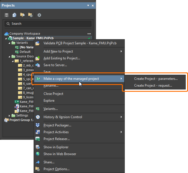
Added support for making a copy of a Workspace project using defined (and enabled) process workflows. When a Workspace project is opened, right-click the project entry in the Projects panel and select an activated process definition (that is part of the Project Creations theme) from the Make a copy of the managed project sub-menu to start copying the project in accordance with the underlying workflow for that process.
For more information, refer to the Process-based Project Creation page.
Added Ability to Preserve Lifecycle State when Releasing Models
When releasing a new revision of a component model (schematic symbol, PCB footprint, simulation model, or harness wiring) to the connected Workspace, you can now preserve the model's current lifecycle state.
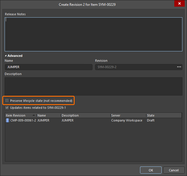
Note that this ability is available for those with assigned Allow to skip lifecycle state change for new revisions operational permission (learn more about Setting Global Operation Permissions for a Workspace).
For more information about editing Workspace content, refer to the Creating & Editing Content page.
Design Review Comment Links
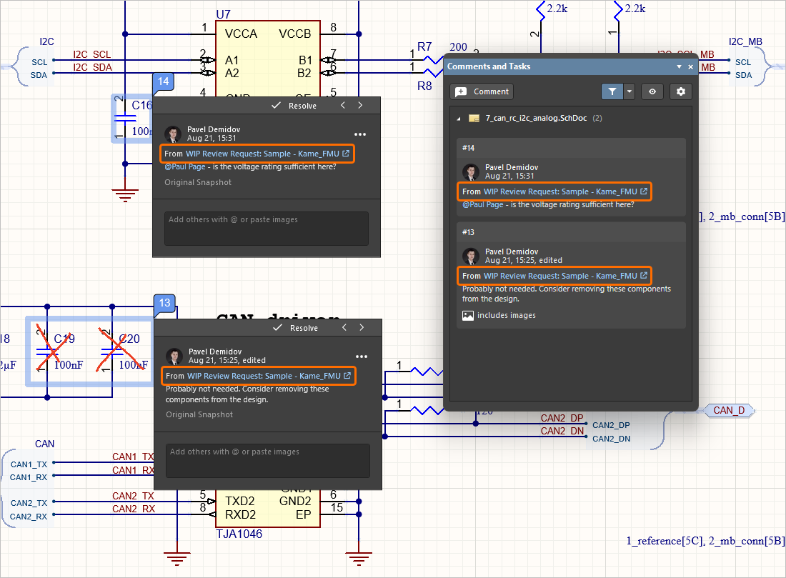
When a comment is added as part of a design review, a link to that review (From <DesignReviewName>) is now presented within a corresponding entry in the Comments And Tasks panel and the contextual commenting window for that comment (within the design space). Click the link to open the review's Overview page in a new tab of your default browser.
For more information about document commenting, refer to the Document Commenting page.
Support for Additional Unit-aware Data Types
When defining a user parameter as part of a component template in a connected Workspace on the Altium Platform, the following additional unit-aware data types are now supported:
-
Area (mm2)
-
Bar (bar)
-
Bit
-
Candela (cd)
-
Decimal
-
Integer
-
Joule (J)
-
Lumen (lm)
-
Millimetre (mm)
-
Pascal (Pa)
-
Pounds per square inch (psi)
-
Rotations per minute (rpm)
-
Siemens (S)
-
Tesla (T)
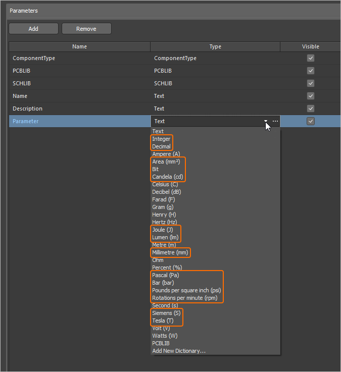
Parameters using these new unit types are supported in various areas of the software, including the Components panel, the Component editor (in both single and batch editing modes), and by the Library Importer and Components Synchronization feature (in the Parameter Mapping section of the Properties panel).
For more information about the unit-aware component parameter data types, refer to the Component Templates page.
Ability to Sync Part Choices when Using Components Synchronization
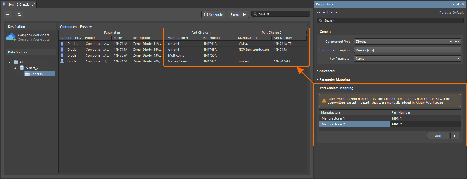
The ability to define and sync part choice information using the Components Synchronization feature and its related Components Synchronization Configuration document (*.CmpSync) has been added. Control of the synchronized parameters is available in the Part Choices Mapping region of the Properties panel when a table is selected in the document. Use the buttons to add and remove part choice parameter pairs (Manufacturer / Part Number) and drop-down menu options to define the mapping. When mappings are defined, the corresponding parameters appear under Part Choice n columns in the document grid area.
For more information about the Components Synchronization feature, refer to the Component Database to Workspace Data Synchronization page.
New Warning Regarding Problems Connecting to a Workspace
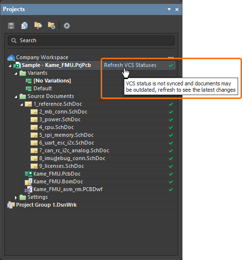
If there is an issue connecting to a Workspace and the latest VCS states of project documents are not able to be refreshed, the Refresh VCS Statuses control (with associated tool-tip warning) now appears next to the project entry in the Projects panel. Once connection resumes, click the entry to bring the VCS states back into sync and to see the latest changes.
For more information about indicating document status, refer to the Managing Project Documents page.
BOM CoDesign Improvement
Excluding Supplier-related Fields from BOM Comparison Result (Open Beta)
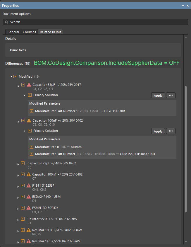
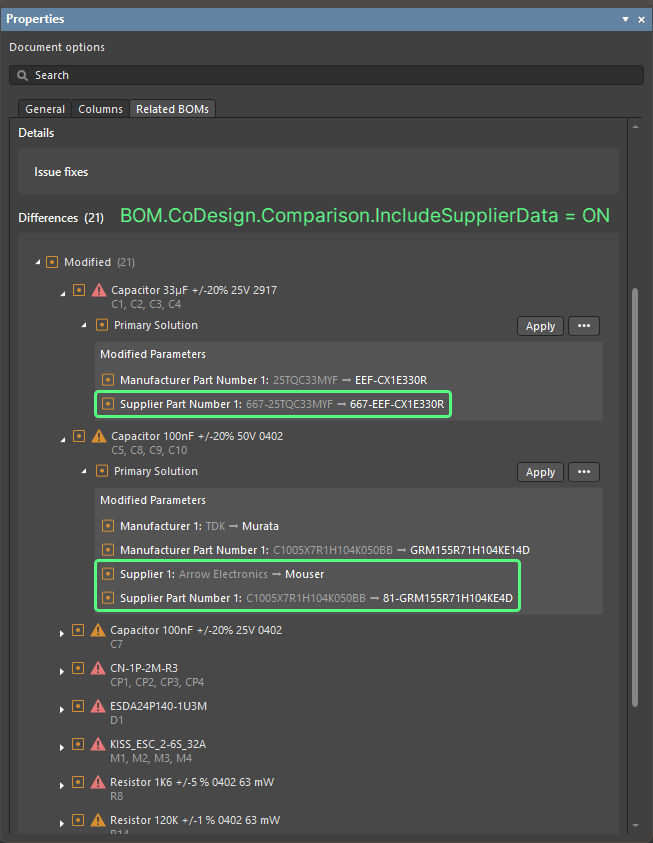
When comparing an ActiveBOM with a selected Managed BOM by using the BOM CoDesign feature, when the advanced setting is disabled, supplier-related data (Supplier and Supplier Part Number parameters) is excluded from the Differences section on the Related BOMs tab of the Properties panel when it has been accessed from an ActiveBOM document.
For more information about exploring comparison results, refer to the BOM CoDesign page.
Import/Export Improvements
Enhanced Allegro Design Imports
All configuration files that are required are now included in the Allegro2Altium.bat file, a batch file included in your Altium Designer installation and used to convert an Allegro binary (*.brd or *.dra) file to ASCII format (when such a design/library is not on the same PC as Altium Designer). Therefore only the bat file is required for the import and no additional files.
For more information about exploring comparison results, refer to the Importing a Design from Allegro page.
Support for Component Alternative Views from xDX Designer Designs
Alternate view modes for components are now supported, in both generated schematic and schematic library documents, when importing an xDX Designer design.
For more information about exploring comparison results, refer to the Importing a Design from xDX Designer or DxDesigner page.
Features Made Fully Public in Altium Designer 26.1
The following features are now officially Public with this release:
-
Detailed Pad Stack for Allegro Imports - available since 25.7
-
Properties Panel Optimization for PCB Object Properties - available since 25.7
Additional Features in Altium Designer 26.1
-
Hidden Links to External VCS Repositories (Open Beta): A new advanced settings option –
VCS.HideProjectExternalRepositoriesLinks– is available in the Advanced Settings dialog with this release which, when enabled, hides links to external VCS repositories (created automatically when making a project under external VCS available to a connected Workspace) on the Data Management – Design Repositories page of the Preferences dialog (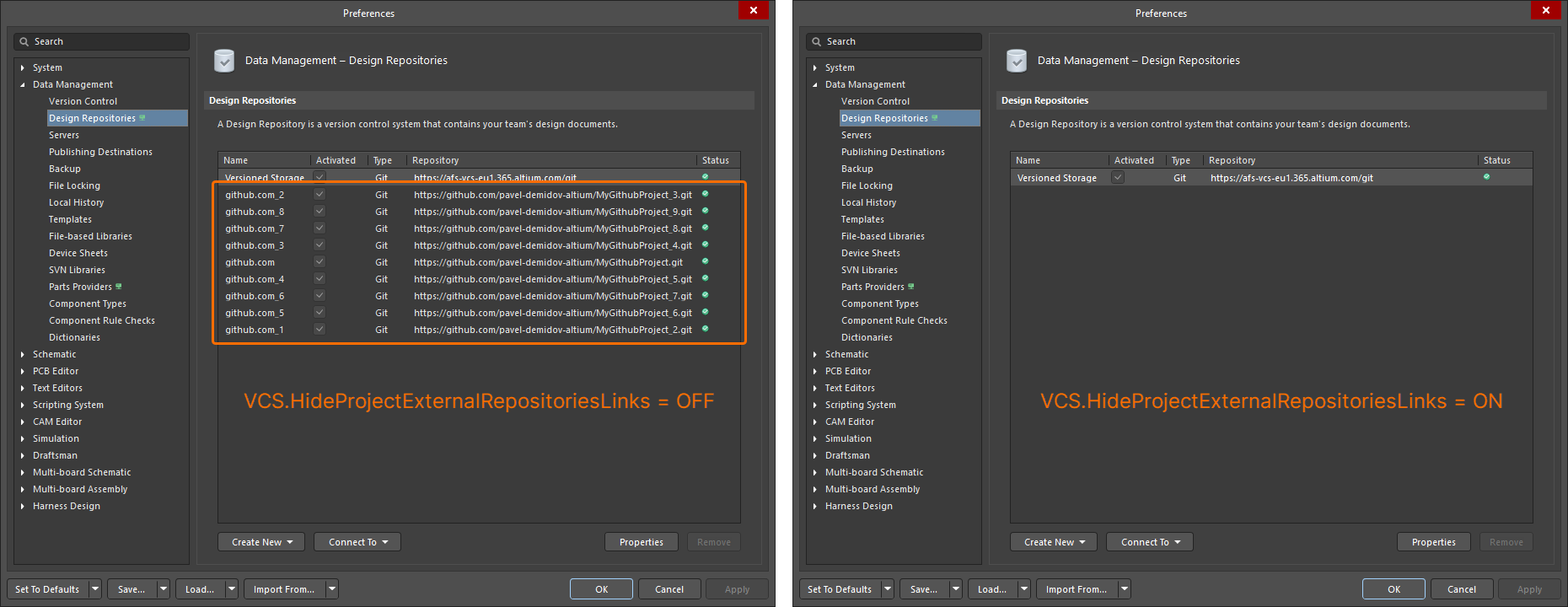 ).
).
-
Simbeor Version (Open Beta): A new advanced settings option –
PCB.SimbeorVersion– is available in the Advanced Settings dialog with this release. This feature controls the version of Simbeor used in the calculation of delay and impedance (Simbeor 2020.3 (option '0') or Simbeor 2023.1 (option '1')). -
Via Instancing (Open Beta): A new advanced settings option –
PCB.ViaInstancing– is available in the Advanced Settings dialog with this release. When this option is enabled, the concept of 'via instancing' is utilized, an approach for building the geometry of an instance of a via, rather than a via template. This enhances performance while reducing both memory consumption and scene building time. -
Loading Optimization of Pad and Via Templates (Open Beta): A new advanced settings option –
PCB.Performance.PadViaTemplate.LoadingOptimization– is available in the Advanced Settings dialog with this release, which speeds up loading of PCBs by optimizing pad and via templates loading. -
ECO Processing Optimization (Open Beta): A new advanced settings option –
WSM.DotNetECOImplementation– is available in the Advanced Settings dialog with this release, which enables the use of accelerated ECO processing functionality.