
QuickNav - Multi-board Schematic Design Objects
This page provides quick reference information about the design objects that can be used in a multi-board schematic document (*.MbsDoc), giving you a means to quickly navigate to more detailed information about each.
Graphical Overview
The following image provides a collated visual of commonly used multi-board schematic design objects.

Design objects that are commonly used in a multi-board schematic document.
Key Objects Slideshow
Take a look through the slides below to see a variety of design objects highlighted 'in action' within a real multi-board design. A high-level intro to each object is given, along with a link to more detailed information. Note that focus is primarily on the objects that you'll use time and again to capture your logical multi-board designs.
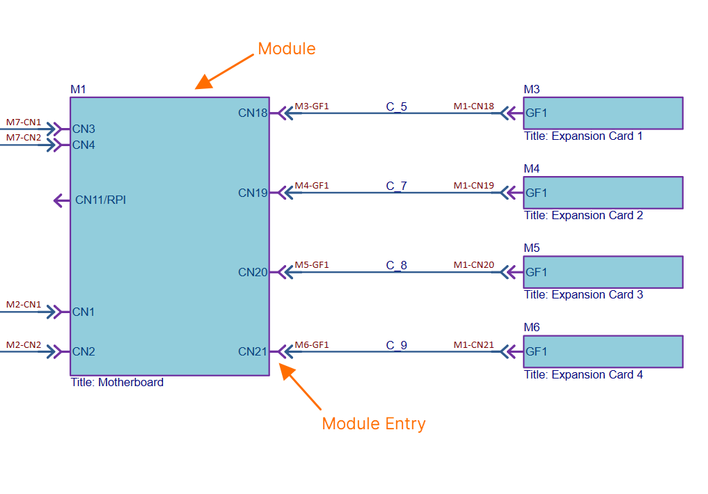
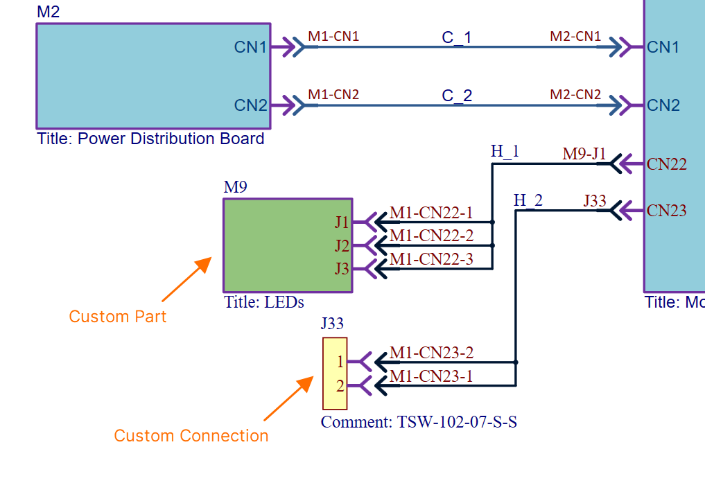
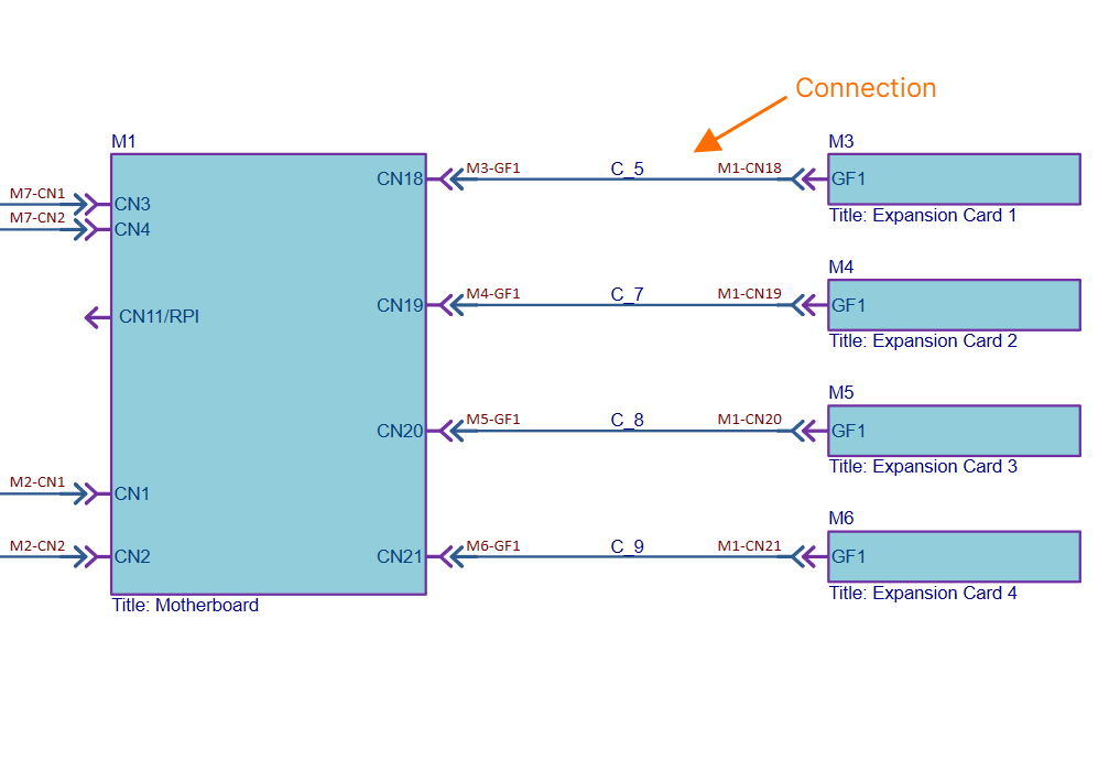
ModuleA module represents a child PCB project (and specific PCB therein) within the overall multi-board design. The number of modules placed on the multi-board schematic document will depend on the number of such child boards involved in capturing the complete system design. A module is populated with design data from its linked PCB project during an import process. This processes the pin and net data from the corresponding connector in the child project, which is identified using the special System parameter (with value Module EntryA module entry is a graphical object that is automatically or manually placed on a module in a multi-board schematic document to represent a connection point (such as a header or plug/socket) of a child PCB project design. After an import process is complete (importing design data from a module's linked child PCB design project), a module entry is automatically created for each of the connectors on the parent module block graphic. The module entry is actively associated with pins and nets on the corresponding connector in the child PCB project. Learn more... The multi-board schematic document supports external peripherals/components not part of the regular child PCB board assemblies (i.e. ‘non-PCB’ components). This capability is facilitated with support for two object types. Custom PartA module-like entity that provides the ability to link one or more library components. An entry is automatically added for each linked component. Custom ConnectionProvides the ability to add a single library component to the multi-board schematic document by dragging and dropping the required component from the Components panel into free space on the sheet. An entry is automatically added for each pin of the component. ConnectionA connection is an object that is placed between module entries in a multi-board schematic document to provide the logical connectivity between modules. Multi-board connections represent the physical connections (plugs and sockets, cables, or harnesses) that are used between the child PCB board designs. Three types of connection are supported:
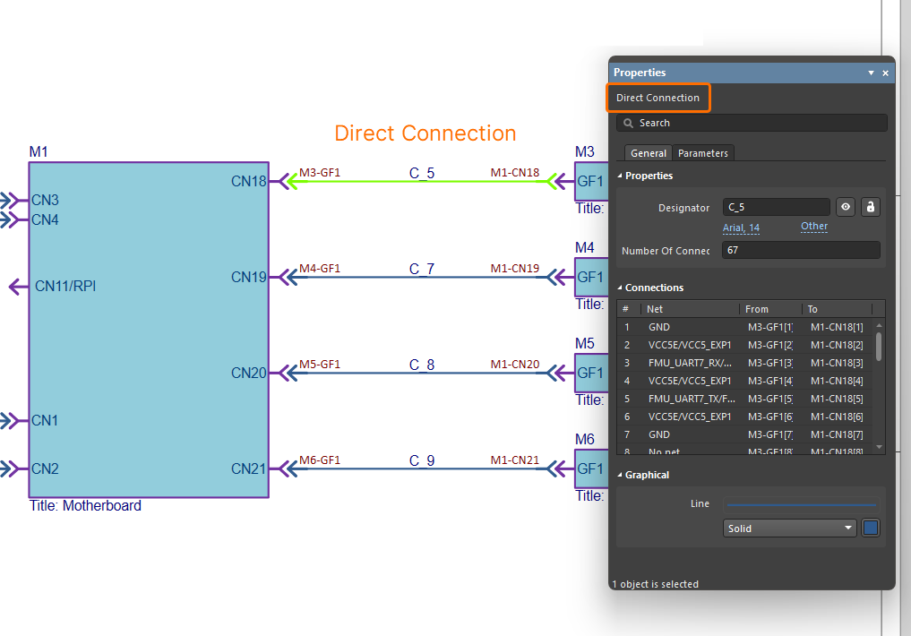
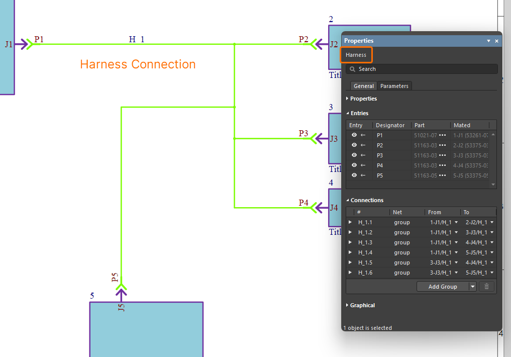
The connections established between modules in the multi-board schematic ultimately represent the connectivity between child project connectors, connector pins and nets in the overall system design. Learn more... Here is an example of a direct connection between two modules in a multi-board design. In this case connector GF1 on an expansion board (represented by module M3) is to plug in directly to connector CN18 on the system's motherboard (represented by module M1). Here is an example of using a single harness to interconnect all modules in a multi-board design. The harness has five connectors (P1-P5) that will plug into the corresponding connectors (J1-J5) on the five child boards in the captured system. You can also benefit from Altium Designer's support for harness design, allowing you to create a full wiring harness design, from the individual pin-to-pin connections right through to manufacturing documentation. A harness is designed within its own design project ( |
Multi-board Schematic Document Commenting
A comment can be applied to an object, a specific point, or an area in a multi-board schematic document. A comment is a user-added note that may be replied to by other users. Comments promote collaboration between users without altering the shared data itself, because comments are stored by the connected Workspace independently of that data. Comments are posted, replied to, and managed directly within the design space using a contextual commenting window in conjunction with the Comments and Tasks panel.
For more information, refer to the Document Commenting page.
A-Z Listing
The following is a convenient alphabetical listing - no frills, no fuss - to be able to get at more detail for a particular design object in true QuickNav fashion.