
Browsing through the PCB Rules and Violations Panel
Parent page: PCB Panels

The PCB Rules And Violations panel
Summary
Design Rule Checking (DRC) is a powerful automated feature that checks both the logical and physical integrity of your design. The PCB Rules And Violations panel allows easy browsing of the enabled design rules and violations in the current board layout workspace. The panel provides a central point for browsing and editing rules, instigating design rules checks, and viewing individual violations as graphic overlays in the editor workspace.
Panel Access
- To display the PCB Rules And Violations panel, click the Panels button at the bottom-right of Altium NEXUS when the PCB Editor is active then select the PCB Rules And Violations entry.
- Alternatively, you can access the panel by clicking View » Panels » PCB Rules And Violations.
- When a DRC batch process completes, the PCB Rules and Violations panel automatically launches.
Selecting Rules and Violations
The body of the PCB Rules And Violations panel has four sections, each offering a finer scope of the design rules and violations:
- Rule Classes - Design rules grouped by classes, such as Clearances and Widths.
- Rules - The individual design rules of the selected class. The specific DRC can be run via the right-click menu.
- Violations - Details of each rule violation reported by activated design rules checks.
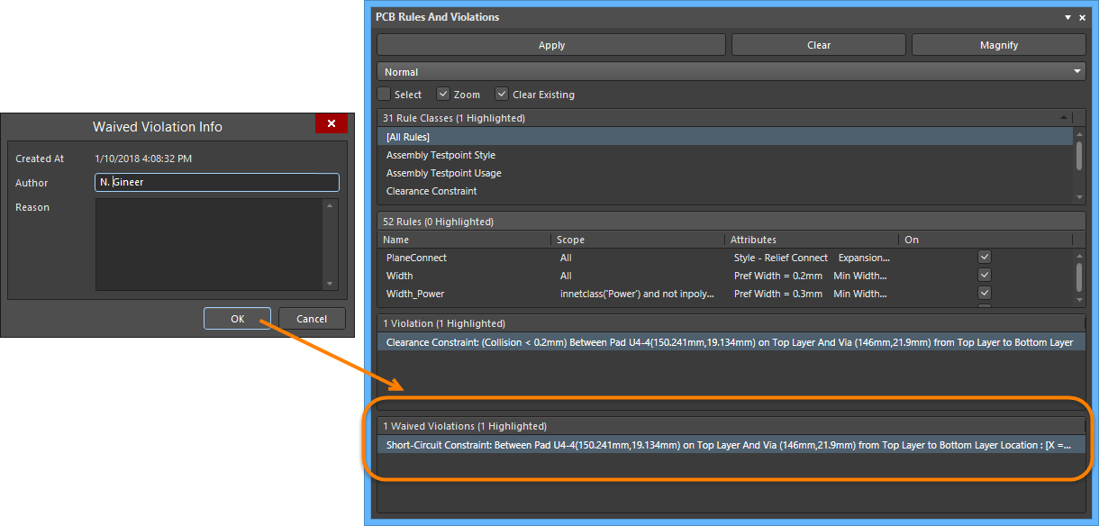
- Waived Violations - Details of each waived rule violation reported using the Waive Selected Violations command. This section is visible only after at least one violation has been waived.
Selecting an individual rule violation causes the design workspace to graphically highlight that violation. Enhanced violation graphics are drawn only on the layers on which the offending primitives reside, and that layer (if enabled) will become the active layer in the workspace. When the rule violations details are enabled (see below), the editor's graphics will display the constraint value defined for the rule and indicate how the offending primitive(s) are either below or above this value.

Violation of a minimum Width rule set to 12mil.

Violation of a Via dimension rule set to minimums of 50mil diameter and 28mil hole size.
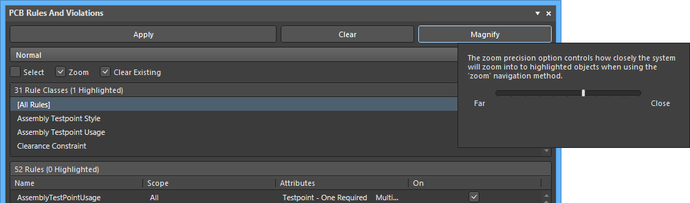
Note that if you have the Zoom highlighting method enabled, the workspace will be zoomed-in to fit the browsed violation for a much more precise 'view' of the violating area. The level of that zoom can be varied via the panel's Magnify button.
You can also directly access violations from within the design workspace. With the cursor over an offending primitive, right-click and select Violations from the context menu, then select the appropriate violation to open the Violation Details dialog.

Controlling the Display of DRC Violations
The visual display of DRC violations can be configured to maximize clarity and/or suit your own preferences by setting the style, number and color of the graphic markers. Along with the graphic display of violation details, the design primitives can be overlaid with a graphic pattern selected from a number of styles.
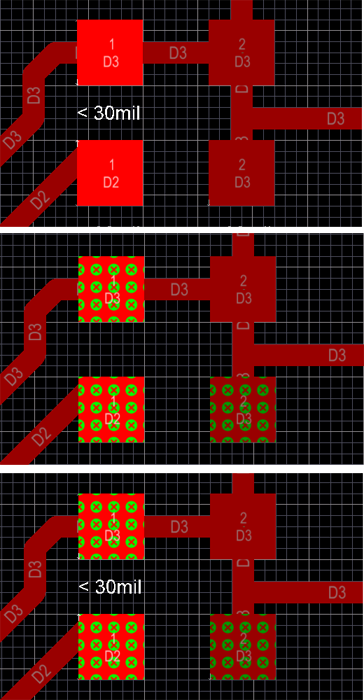
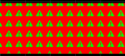
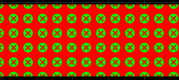
Top: Violation details enabled. Middle: Violation error overlay enabled.
Bottom: Both details and error overlay enabled.
Violation Display Preferences
Control over how DRC violations are displayed using the custom violation graphics and/or a defined violation overlay is specified on the PCB Editor – DRC Violations Display page of the Preferences dialog.

Choose how you want DRC violations to be displayed in the workspace - using custom graphics and/or a defined violation overlay.
Specifying the Overlay Style
Use the options in the Violation Overlay Style region of the page to specify the style of violation overlay to use. The table below illustrates example results for a routed track on the Top Layer in violation of a Width rule based on the chosen violation overlay style.
|
Selected Style
|
Description
|
Example Result
|
|---|---|---|
|
None (Layer Color)
|
The DRC override color is ignored, |
|
|
Solid (Override Color)
|
The DRC override color is used, |
|
|
Style A
|
The DRC override color is used in the display |
|
|
Style B
|
The DRC override color is used in the display |
|
Specifying Violation Display Style for each Rule Type
The Choose DRC Violations Display Style region of the dialog presents a grid allowing you to choose the display style used on a per-rule basis. Enabling the Violation Details field for a rule type will use the associated custom violation graphics to display the DRC violations of that rule. Enabling the Violation Overlay field will display the violations using the specified overlay style.
Right-click within the grid to access a menu of commands to quickly enable or disable use of a violation display type for all rule types. You can also quickly enable the display of violations – detailed graphics or overlay styles – for only those rules currently being used in the design.

Use the grid and related commands to set up exactly how DRC violations will be displayed in the workspace.
Using the two display types together can prove useful in terms of providing a 'coarse' and 'fine' indication of violations.
Right-Click Menus
The entries in each section of the panel offer a range of options via the right-click context menu. Notable right-click options for each section are:
Rule Classes
- Run DRC Rule Class - runs all rules contained in the class. Classes may only contain a single rule (such as Short-Circuit Constraint) or a large number (typically, the Clearance Constraint class).
- Clear Violations For Rule Class - clears the violations (both graphically and listed in the panel) for all rules contained in the class.
Rules
- Run DRC Rule - runs the selected rule.
- Clear Violations - clears the violations reported by the selected rule.
- Properties - opens the Edit PCB Rule dialog that allows the rule configuration to be changed on the fly.

Violations
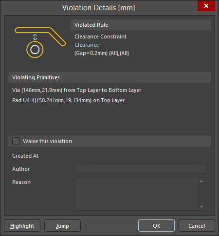
- Properties - opens the Violation Details dialog, which provides full details of the rule constraint and the current violation.
- Waive Selected Violations - opens the Waived Violation Info dialog in which information can be entered and saved about the violation selected to be waived. After entering the necessary information and clicking OK, the waived violations are displayed under the Waved Violations region.
Tips
- For full access to the PCB Constraint Classes and Rules, open the PCB Rules and Constraints Editor dialog by clicking Design » Rules.
- Online Design Rule Checking can be enabled/disabled in the PCB Editor - General page of the Preferences dialog.
- Design Rules can be individually enabled for Online or Batch checking (or both) in the Design Rule Checker dialog (Tools » Design Rule Check).