
Harness Connector Properties
Created: April 08, 2021 | Updated: November 22, 2021
| Applies to version: 4
This document is no longer available beyond version 4. Information can now be found here: Harness Connector Properties for version 5
Parent page: Harness Connector
Schematic Editor object properties are definable options that specify the visual style, content and behavior of the placed object. The property settings for each type of object are defined in two different ways:
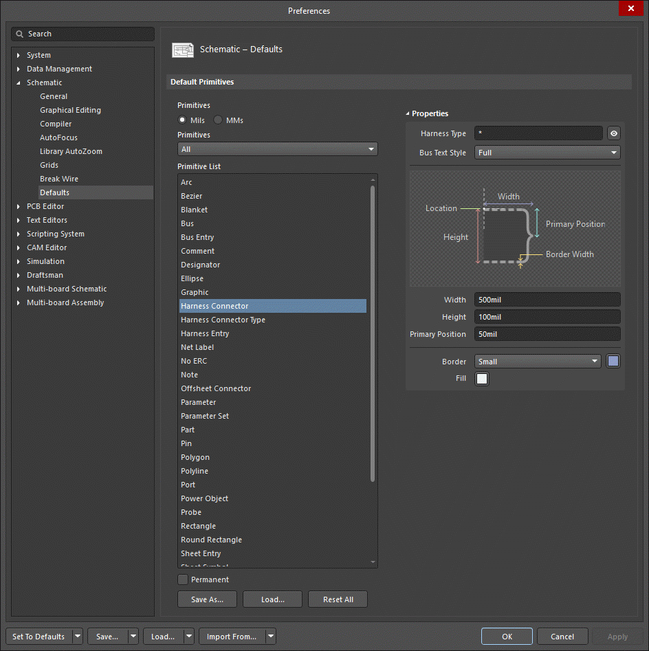
- Pre-placement settings – most Harness Connector object properties, or those that can logically be pre-defined, are available as editable default settings on the Schematic - Defaults page of the Preferences dialog (accessed from the
 button at the top-right of the design space). Select the object in the Primitive List to reveal its options on the right.
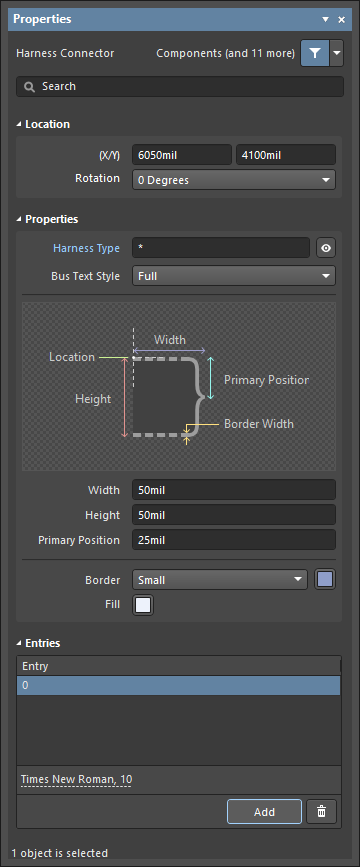
- Post-placement settings – all Harness Connector object properties are available for editing in the Properties panel when a placed Harness Connector is selected in the design space.
Location (Properties panel only)
- (X/Y)
- X (first field) - the current X (horizontal) coordinate of the reference point of the object, relative to the current design space origin. Edit to change the X position of the object. The value can be entered in either metric or imperial; include the units when entering a value whose units are not the current default.
- Y (second field) - The current Y (vertical) coordinate of the reference point of the object, relative to the current origin. Edit to change the Y position of the object. The value can be entered in either metric or imperial; include the units when entering a value whose units are not the current default.
- Rotation - use the drop-down to select the rotation.
Properties
- Harness Type - enter the name of the harness. Click the eye icon to show/hide harness name.
- Bus Text Style - use the drop-down to select the style:
- Full - select to show full identifiers of the connected buses in format <Name>[<StartingNumericalIdentifer>..<EndingNumericalIdentifier>] (for example,
SW[0..7]). - Prefix - select to show only prefixes of connected buses in format <Name> (for example,
SW).
- Full - select to show full identifiers of the connected buses in format <Name>[<StartingNumericalIdentifer>..<EndingNumericalIdentifier>] (for example,
- Width - can be edited.
- Height - can be edited.
- Primary Position - can be edited.
- Border - use the drop-down to select the default from the available choices.
- Fill - click on the colored box to access a drop-down from which you can select the default color.
Entries (Properties panel only)
Use this region to manage the connector's associated harness entries.
- Harness Entries Grid - the grid lists all of the harness entries currently defined for the harness connector.
- Add - click to add a new harness entry to the connector. The new entry will be added at the bottom of the list and given the default name of 0. Click
 to delete the currently selected entry from the grid.
 - Font - click on the displayed font to change the font style in various ways.