
Off Sheet Connector Properties
Created: December 15, 2020 | Updated: August 23, 2021
| Applies to version: 4
This document is no longer available beyond version 4. Information can now be found here: Off Sheet Connector Properties for version 5
Parent page: Off Sheet Connector
Schematic Editor object properties are definable options that specify the visual style, content and behavior of the placed object. The property settings for each type of object are defined in two different ways:
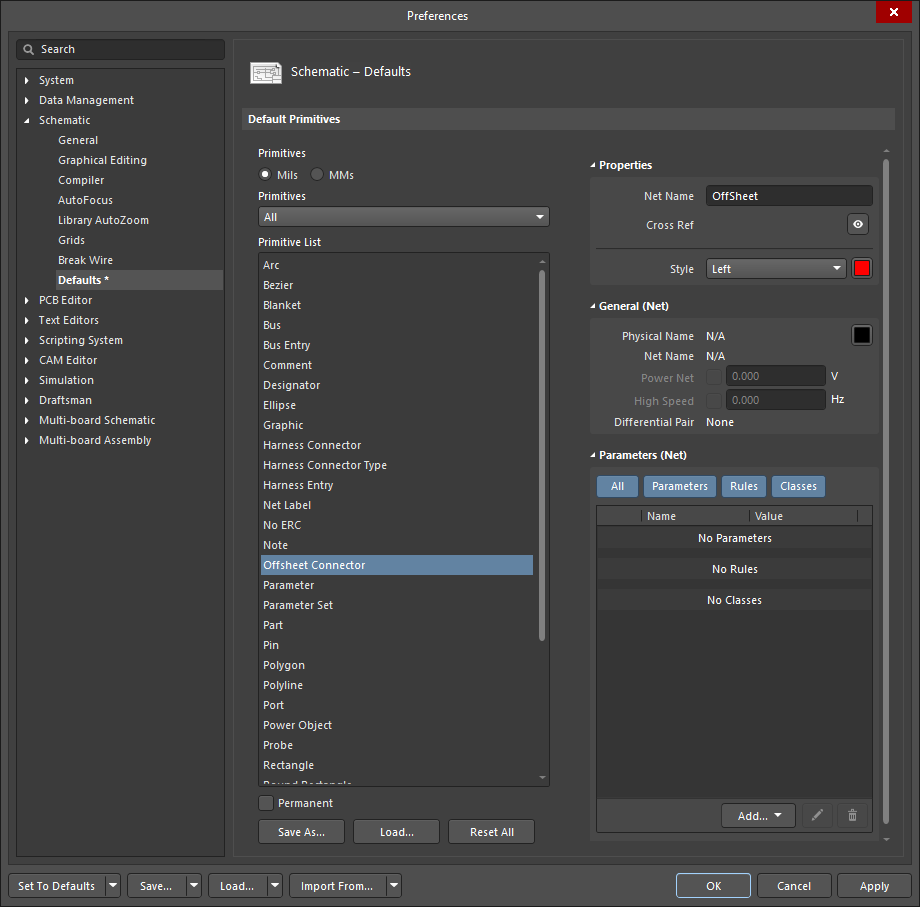
- Pre-placement settings – most Off Sheet Connector object properties, or those that can logically be pre-defined, are available as editable default settings on the Schematic - Defaults page of the Preferences dialog (accessed from the
 button at the top-right of the workspace). Select the object in the Primitive List to reveal its options on the right.
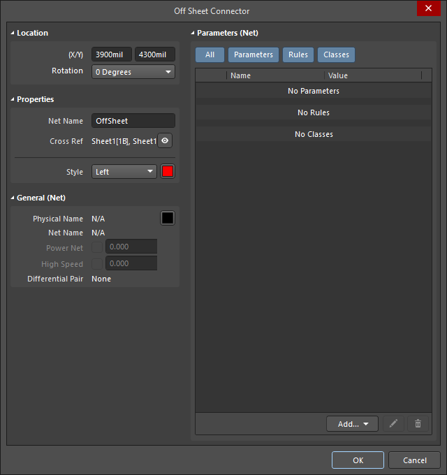
- Post-placement settings – all Off Sheet Connector object properties are available for editing in the Off Sheet Connector dialog and the Properties panel when a placed Off Sheet Connector is selected in the workspace.
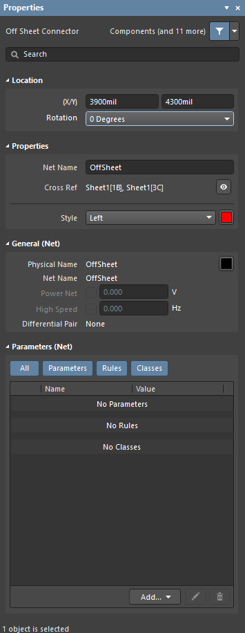
Location (Properties panel only)
- (X/Y)
- X (first field) - the current X (horizontal) coordinate of the reference point of the object, relative to the current workspace origin. Edit to change the X position of the object. The value can be entered in either metric or imperial; include the units when entering a value whose units are not the current default.
- Y (second field) - The current Y (vertical) coordinate of the reference point of the object, relative to the current origin. Edit to change the Y position of the object. The value can be entered in either metric or imperial; include the units when entering a value whose units are not the current default.
- Rotation - use the drop-down to select the rotation. Choices are: 0 Degrees, 90 Degrees, 180 Degrees, and 270 Degrees.
Properties
- Net Name - enter the net name.
- Cross Ref - this field displays cross reference values that are applied to the offsheet connector.
- Style - use the drop-down to select the default from the available choices: Left or Right. Click on the color box to access a drop-down from which you can select the default color.
General (Net)
Displays the properties of the nets assigned to the off sheet connector. Update as needed.
Parameters (Net)
- Selection buttons - click the desired objects to display in the grid.
- Add - use the drop-down to add the desired object(s) then define the values.