
Parameter Set Properties
This document is no longer available beyond version 4. Information can now be found here: Parameter Set Properties for version 5
Parent page: Parameter Set
Schematic editor object properties are definable options that specify the visual style, content and behavior of the placed object.
The property settings for each type of object are defined in two different ways:
-
Pre-placement settings – most Parameter Set object properties, or those that can logically be pre-defined, are available as editable default settings on the Schematic – Defaults page of the Preferences dialog (accessed from the
 button at the top-right of the design space). Select the object in the Primitive List to reveal its options on the right.
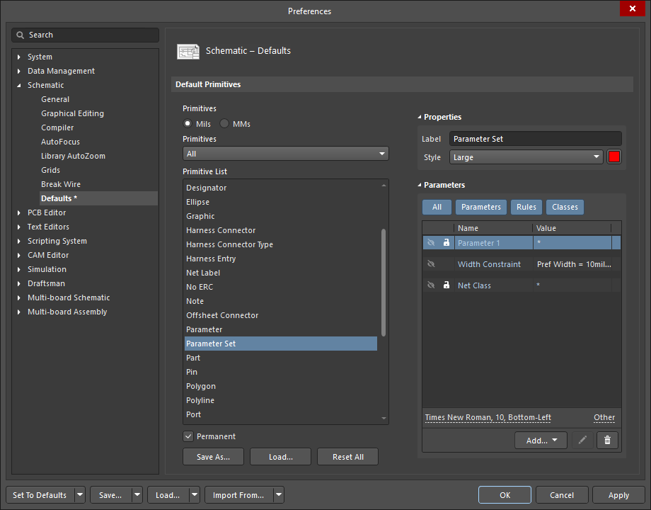
-
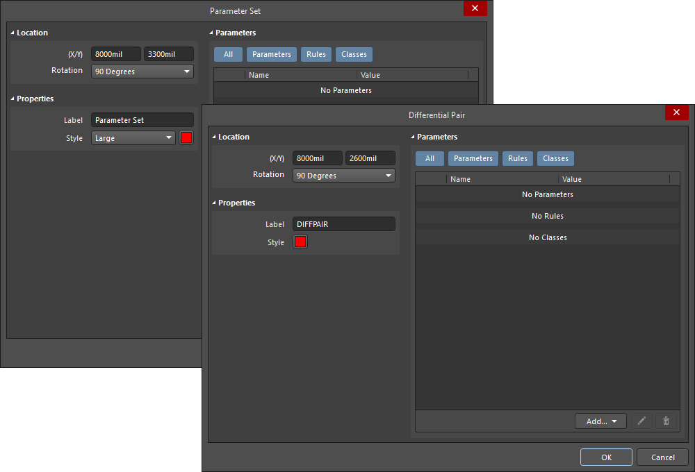
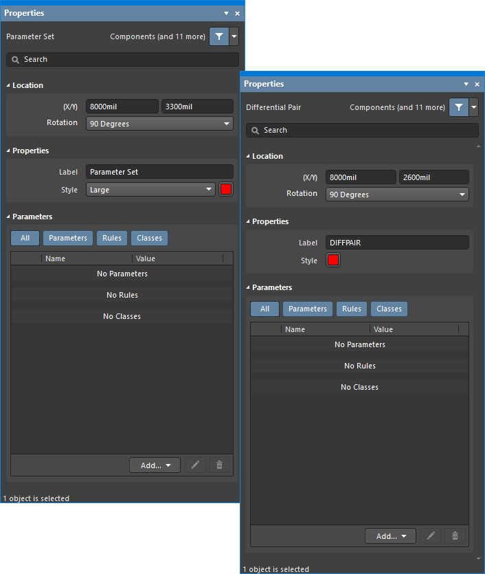
Post-placement settings – all Parameter Set object properties are available for editing in the Parameter Set dialogs and the Properties panel when a Parameter Set is selected in the design space.
Location
- (X/Y)
- X (first field) – the current X (horizontal) coordinate of the reference point of the object, relative to the current design space origin. Edit to change the X position of the object. The value can be entered in either metric or imperial; include the units when entering a value whose units are not the current default.
- Y (second field) – the current Y (vertical) coordinate of the reference point of the object, relative to the current origin. Edit to change the Y position of the object. The value can be entered in either metric or imperial; include the units when entering a value whose units are not the current default.
- Rotation – use the drop-down to select the rotation.
Properties
- Label – the parameter set label. Edit if desired.
- Style – use the drop-down to select the style. Click on the color box to access a drop-down from which you can select the default color.
Parameters
- Grid – lists the Name and Value of the parameters associated with the currently selected parameter. Once added, the Name and Value fields may be edited. The Value can be named by clicking on the field and entering the desired text. The Name field may only be changed when in the Properties panel mode of the Parameter Set object by using Ctrl+Click. This method opens the Parameter mode of the Properties panel, where you can enter the desired name within the Name field. Use the lock icon (
 ) to lock/unlock a listed parameter. Use the eye icon to show/hide the parameter. All, individual, or no parameters can be displayed within this region by toggling the All and individual parameter buttons. The parameters are disabled when their respective buttons are gray and enabled when their respective buttons are blue.
 - Add – use the drop-down to add a type of class:
- Net Class – select to add a new net class.
- Diff. Pair Net Class – select to add a new differential pair net class. This option is accessible in the Differential Pair iteration of the Parameter Set dialog or Properties panel only.
- Parameter – select to add a new parameter class.
- Rule – click to open the Choose Design Rule Type dialog in which you can choose a new rule. After choosing a new rule then clicking OK, the Edit PCB Rule (From Schematic) dialog opens so that you can edit the new rule if desired.
Click the pencil ( ![]() ) icon to open the Edit PCB Rule (From Schematic) dialog to edit the selected item. Click
) icon to open the Edit PCB Rule (From Schematic) dialog to edit the selected item. Click  to delete the selected item.
- Font Settings – click on the displayed font to change the font style. This option is only available once a net class, differential pair net class, parameter, or rule has been added.
- Other – If a net class, differential pair net class, parameter, or rule has been added, click to open a drop-down to change additional options:
- Show Parameter Name – enable to show the parameter name.
- Allow Synchronization with Database – enable to synchronize with the database.
- X/Y – enter the X and Y coordinates.
- Rotation – use the drop-down to select the rotation.
- Autoposition – check to enable auto-positioning.