
Working with a Harness Entry Object on a Schematic Sheet in Altium Designer
This document is no longer available beyond version 21. Information can now be found here: Harness Entry for version 24
Parent page: Schematic Objects
 A placed Harness Entry
Summary
A Harness Entry is an electrical design primitive that is placed within a Harness Connector. A Harness Entry is the connection point through which signals - through wires, buses, and other signal harnesses - are combined to form a higher-level Signal Harness. Signal Harnesses enable the logical grouping of different signals for increased flexibility and streamlined design.
Availability
Harness Entries are available for placement in the Schematic Editor only in the following ways:
- Choose Place » Harness » Harness Entry from the main menus.
- Click the
 button on the Wiring toolbar.
 - Click the Harness Entry button () in the graphic objects drop-down on the Active Bar located at the top of the design space. (Click and hold an Active Bar button to access other related commands. Once a command has been used, it will become the top-most item on that section of the Active Bar.)
- Right-click in the design space then choose Place » Harness » Harness Entry from the context menu.
Harness entries can also be managed in the following non-graphical ways:
- Added/edited/removed in the Entries region of the Harness Connector mode of the Properties panel.
- Added/edited/removed as part of the textual harness connector definition through a harness definition file (*.Harness). This defined harness connector can only be placed in the design using the Place » Harness » Predefined Harness Connector command from the main menus.
Placement
After launching the command, the cursor will change to a cross-hair and you will enter harness entry placement mode. Placement is made by performing the following sequence of actions:
- Move the harness entry attached to the cursor over a placed harness connector on the sheet.
- Adjust the position of the harness entry in relation to the edge of the harness connector, opposite the connector's tip, then click or press Enter to anchor the harness entry and complete placement.
- Continue placing further harness entries or right-click or press Esc to exit placement mode.
While the harness entry is still floating on the cursor and while it is within the bounds of a harness connector, press the Tab key to pause the placement and access the Harness Entry mode of the Properties panel in which its properties can be changed on the fly. Click the design space pause button overlay (  ) to resume placement.
Graphical Editing
This method of editing allows you to select a placed harness entry object directly in the design space and change its location graphically.

A selected Harness Entry
- Click and drag to reposition the harness entry vertically along the edge of its parent harness connector as required.
- Hold Ctrl then click and drag the harness entry to move it from the current harness connector to another harness connector on the sheet. Once the harness entry has cleared the boundary of the source harness connector, the Ctrl key can be released.
- Clicking and dragging the harness entry outside of the harness connector boundary will cause the harness connector to automatically resize to accommodate the entry's new location.
- The name text for a harness entry object can be edited in-place by:
- Single-clicking the harness entry to select it.
- Single-clicking again (or pressing Enter) to enter the in-place editing mode. Sufficient time between each click should be given to ensure the software does not interpret the two single-clicks as one double-click.
- To finish editing in-place text, press Enter or use the mouse to click away from the harness entry.
Non-Graphical Editing
The following methods of non-graphical editing are available.
Editing via the Harness Entry Dialog or Properties Panel
Properties page: Harness Entry Properties
This method of editing uses the associated Harness Entry dialog and the Properties panel mode to modify the properties of a harness entry object.
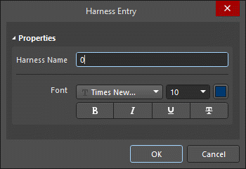
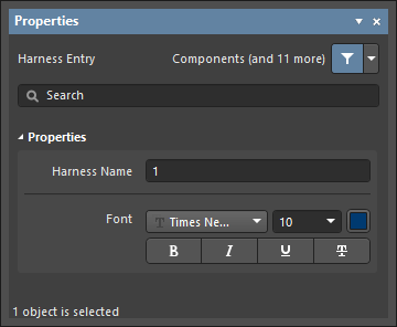 The Harness Entry dialog, on the left, and the Harness Entry mode of the Properties panel on the right
After placement, the Harness Entry dialog can be accessed by:
- Double-clicking on the placed harness entry object line.
- Placing the cursor over the harness entry object line, right-clicking then choosing Properties from the context menu.
During placement, the Harness Entry mode of the Properties panel can be accessed by pressing the Tab key. Once the harness entry is placed, all options appear.
After placement, the Harness Entry mode of the Properties panel can be accessed in one of the following ways:
- If the Properties panel is already active, by selecting the harness entry object.
- After selecting the harness entry object, select the Properties panel from the Panels button in the bottom right section of the design space or select View » Panels » Properties from the main menu.
Editing via a List Panel
Panel pages: SCH List, SCH Filter
A List panel allows you to display design objects from one or more documents in tabular format, enabling quick inspection and modification of object attributes. Used in conjunction with appropriate filtering by using the SCH Filter panel or the Find Similar Objects dialog, it enables the display of just those objects falling under the scope of the active filter allowing you to target and edit multiple design objects with greater accuracy and efficiency.
Notes
- A Harness Entry can be connected directly to a wire, a bus or a signal harness. The Harness Type field in the Harness Connector mode of the Properties panel is used when nesting signal harnesses. The field will auto-populate with the Harness Type of the connected signal harness.
- If you need to negate (place a bar over the top of) a harness entry name, this can be done in two ways:
- By including a backslash character after each character in the name (e.g., E\N\A\B\L\E\).
- By enabling the Single '\' Negation option on the Schematic- Graphical Editing page of the Preferences dialog, then including one backslash character at the start of the name (e.g.,\ENABLE).