大規模な設計における一般的な課題は、ネットを管理しやすく保つことです。これは、接続性を作成する設計者の観点だけでなく、回路図を解釈して理解する必要がある読者の観点からも重要です。これは、シート間の接続を行う際に、設計者と読者の両方が最も混乱しやすい時です。
設計に高ピン数のコンポーネントが含まれる場合、個々のワイヤーを使用してすべての接続性を作成することは現実的ではありません。Data0、Data1など、数値的に増加するセットのメンバーである場合、複数のネットを
バスにまとめることができます。または、任意の組み合わせのネットとバスを
シグナルハーネスにまとめることができます。これは、設計全体で複数のネットを視覚的かつ論理的に整然と転送する方法を提供します。
バスの使用
バスは、アドレスバスやデータバスなど、一連の連続するネットを束ねるために使用されます。バスの基本要件は、各ネットが共通の基本名に数値識別子を付けて命名されることです。以下の画像に示されているように、例えば、ネットControl1、Control2、Control3はバスControl[1..3]に束ねることができます。バスは、Enable、Read、Statusなどの関連性のない一連のネットを束ねるためには使用できません。これを行うには、以下で説明するように、シグナルハーネスが使用されます。
有効なバスを作成するには、以下の画像に示されているように、これらの要素をすべて含める必要があります:
- 各ネットにネットラベル
- バスラインにネットラベル
- このシートを離れる場合、バスと同じ名前のポート


上の画像に示されている要素はすべて、有効なバスを作成するために含まれている必要があります。バスの両側から異なるバス要素を引き裂きたい場合にのみ、バスエントリを使用する必要があります。
バスはPCBに転送されず、代わりに各スキーマティックバスごと、または必要に応じて各バスセクションごとにネットクラスを作成できます。バスセクションは、例えばバスD[15..0]から、実際にはより大きなバスのセクションであるバスを指定することによって作成されます。このオプションが有効になっている場合、PCBにはバス全体のネットクラスと、定義された各セクションのネットクラスが含まれます。プロジェクトのオプションダイアログのクラス生成タブで必要なオプションを有効にしてください。
バスは、複数のネットの接続を定義するために他の接続されたオブジェクトと共に使用されるポリラインオブジェクトです。
## 概要
バスは、マルチワイヤ接続を表すポリラインオブジェクトであり、電気設計の基本要素です。
## 利用可能性
バスは、スキーマティックエディタでのみ以下の方法で配置できます:
- スキーマティックエディタのメインメニューから「配置」>「バス」を選択します。
- 設計スペースの上部にある「アクティブバー」のネット配線オブジェクトドロップダウンでバスボタンをクリックします。アクティブバーのボタンをクリックして押し続けると、他の関連コマンドにアクセスできます。コマンドを使用すると、そのセクションのアクティブバーの最上部の項目になります。
- 「配線」ツールバーのボタンをクリックします(「表示」>「ツールバー」>「配線」でアクティブにします)。
- 右クリックしてコンテキストメニューから「配置」>「バス」を選択します。
## 配置
コマンドを起動すると、カーソルがバス配置モードを示す十字線に変わります。次の一連のアクションを実行して配置します:
1. バスの開始点をアンカーするためにクリックまたはEnterキーを押します。
2. カーソルを位置づけてから、バスの形状を定義する一連の頂点点をアンカーするためにクリックまたはEnterキーを押します。
3. 最後の頂点点を配置した後、右クリックまたはEscキーを押してバスの配置を完了します。
4. さらにバスオブジェクトを配置するか、右クリックまたはEscキーを押して配置モードを終了します。
5. BackspaceキーまたはDeleteキーを使用して、最後に配置したバスセグメントを削除します。
### 配置モード
バスを配置する際には、角の方向オプションを持つ2つを含む3つの「手動」配置モードがあります。これらのモードは、バスを配置する際に角がどのように作成されるか、およびバスを配置できる角度を指定します。
配置中:
- Tabキーを押して配置を一時停止し、「バス」モードのプロパティパネルにアクセスして、その場で線のプロパティを変更できます。配置を再開するには、デザインスペースの一時停止ボタンオーバーレイをクリックします。
- Shift+Spacebarを押して、3つの手動モード:90°、45°、任意の角度を切り替えます。
- 90°または45°モード(真の直交モードとして知られている)では、Spacebarを押して角の方向オプションを切り替えます。これらのモードでは、カーソルに接続された線セグメントは先読みセグメントです - 実際に配置されるセグメントはこの先読みセグメントに先行します。
- 配置中、現在の配置モードがデザインスペースの最下部にあるステータスバーに表示されます。バスの配置中にいつでもモードを変更できます。
45度モード
90度モード
任意の角度モード Shift+Spacebarを押して異なる配置モードを切り替えます。
配置中に変更された属性(Tabを使用してプロパティパネルにアクセスすることにより)は、設定の「永続的」オプションが有効になっていない限り、さらなる配置のデフォルト設定になります。このオプションが有効になっている場合、変更は配置中のオブジェクトとその後に配置されるオブジェクトにのみ影響します。
### 自動パスモード
利用可能な4つ目のバス配置モードは、「オートワイヤ」モードであり、ポイントツーポイントルーターを使用して、カーソルがクリックされた点から前のセグメントの端までを迅速にルーティングできます。Shift+Spacebarの選択サイクル中に有効にされると、セグメントの頂点からカーソルまでの太い点線でモードが示されます。
配置されたバスセグメントのオートワイヤモードは、点線のパスラインによって示されます。配置された場合(右)、バスパスは自動的に障害物を回避します。
ルートのパスは、シート上に配置された既存のオブジェクトを回避しながら可能な限り効率的になります。このモードでTabキーを押すと、ポイントツーポイントルーターオプションダイアログで適用可能なオプションを設定できます。
### 電気スナップ
スキーマティックエディタは、グリッドにスナップする機能とともに、利用可能な電気接続にスナップするサポートも提供します。配置中のオブジェクト(バスなど)が有効な電気接続の定義可能なスナップ距離内にある場合、カーソルはその電気「ホットスポット」(赤い十字として表示される)にジャンプします。
電気オブジェクトホットスポットのスナップは、スキーマティック「ドキュメントオプション」モードでプロパティパネルの一般セクションで設定可能です。
## グラフィカル編集
グラフィカル編集方法では、配置されたバスオブジェクトを直接デザインスペースで選択し、そのサイズや形状をグラフィカルに変更できます。
バスオブジェクトが選択されると、次の編集ハンドルが利用可能になります:
- ハンドルでない点をクリックしてドラッグすると、バス全体を再配置できます。バスが選択されていない場合は、クリックして保持し、ドラッグして再配置します。
- Aをクリックしてドラッグして、バスの端点を再配置します。
- Bをクリックしてドラッグして、バスの頂点を移動します。他の頂点は固定されたままです。
- 頂点上でクリックして保持し、キーボードのDeleteキーを押してその頂点を削除します。
バスが選択されて
バスのプロパティ
スキーマティックエディタのオブジェクトプロパティは、配置されたオブジェクトの視覚スタイル、内容、および動作を指定する設定オプションです。各種類のオブジェクトのプロパティ設定は、以下の2つの異なる方法で定義されます:
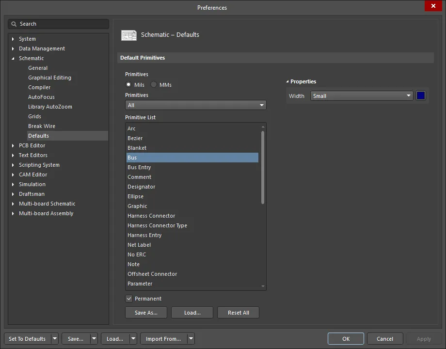
- 配置前の設定 - 多くのバスオブジェクトプロパティ、または論理的に事前に定義可能なものは、デザインスペースの右上にある
 ボタンからアクセスできるPreferencesダイアログのスキーマティック - デフォルトページで、編集可能なデフォルト設定として利用可能です。オブジェクトをプリミティブリストで選択すると、そのオプションが右側に表示されます。
- 配置後の設定 - すべてのバスオブジェクトプロパティは、デザインスペースで配置されたバスが選択されたときに、バスダイアログおよびプロパティパネルで編集可能です。

ダブルクリックでインタラクティブプロパティを実行オプションが無効(デフォルト)に設定されている場合、
スキーマティック - グラフィカル編集ページの
Preferencesダイアログで、プリミティブをダブルクリックするか、選択したプリミティブを右クリックして
プロパティを選択すると、ダイアログが開きます。
ダブルクリックでインタラクティブプロパティを実行オプションが有効になっている場合、
プロパティパネルが開きます。
ダイアログとパネルのオプションは同じですが、オプションの順序と配置が若干異なる場合があります。
以下のプロパティリストでは、Preferencesダイアログのデフォルト設定として利用できないオプションは「プロパティパネルのみ」と記載されています。
プロパティ
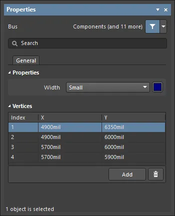
頂点 (プロパティパネルのみ)
この領域は、現在選択されている領域オブジェクトの個々の頂点を変更するために使用されます。既存の頂点の位置を変更したり、新しい頂点を追加したり、必要に応じて削除することができます。頂点間のバス接続を定義するサポートが提供されており、頂点情報をCSV形式のファイルからエクスポートおよびインポートすることもサポートされています。
- 頂点グリッド - オブジェクトに現在定義されているすべての頂点ポイントをリストします。内容は以下の通りです:
- インデックス - 頂点に割り当てられたインデックス(編集不可)。
- X - 頂点のX(水平)座標。クリックして編集。
- Y - 頂点のY(垂直)座標。クリックして編集。
- 追加 - 新しい頂点ポイントを追加するためにクリックします。新しい頂点は、現在フォーカスされている頂点エントリの下に追加され、初期状態ではフォーカスされているエントリと同じX,Y座標を持ちます。現在選択されている頂点を削除するには、
 をクリックします。
 バスエントリは、ワイヤをバスに接続するために使用できます。
概要
バスエントリは、ワイヤをバスラインに接続するために使用される電気設計の基本要素です。これにより、異なるネットがバス上の同じ点に接続できるようになります。これをワイヤを使用して行った場合、2つのネットがショートします。この機能が不要な場合、バスエントリを使用する必要はありません。
利用可能性
バスエントリは、スキーマティックエディタでのみ以下の方法で配置できます。
- メインメニューから配置 » バスエントリを選択します。
- 設計スペースの上部にあるアクティブバーのネット配線オブジェクトドロップダウンでバスエントリボタン(
 )をクリックします。関連する他のコマンドにアクセスするには、アクティブバーのボタンをクリックして保持します。コマンドを使用すると、そのセクションのアクティブバーの最上位項目になります。
- 配線ツールバーのボタンをクリックします(表示 » ツールバー » 配線をクリックしてアクティブにします)。
- 右クリックしてからコンテキストメニューから配置 » バスエントリを選択します。
配置
コマンドを起動すると、カーソルが十字線に変わり、バスエントリ配置モードに入ります。
- カーソル位置にバスエントリを配置するには、クリックするかEnterを押します。
- Spacebarを押してバスエントリを反時計回りに回転させる(90°の増分で)か、Shift+Spacebarを押して時計回りに回転させます。
- 配置モード中にXキーまたはYキーを押して、X軸またはY軸に沿ってバスエントリをミラーリングします。
- バスエントリの配置を続けるか、右クリックまたはEscを押して配置モードを終了します。
配置中にTabキーを押すと、プロセスが一時停止し、プロパティパネルのバスエントリモードにアクセスして、その場で線のプロパティを変更できます。配置を再開するには、デザインスペースの一時停止ボタンオーバーレイ( )をクリックします。
配置中に(プロパティパネルを介して)変更された属性は、設定ダイアログのスキーマティック – デフォルトページで永続オプションが有効になっていない限り、さらなる配置のデフォルト設定になります。このオプションが有効になっている場合、変更は配置中のオブジェクトとその配置セッション中に配置される後続のオブジェクトにのみ影響します。
グラフィカル編集
バスエントリを移動するには、それをクリックして保持します(カーソルが最も近い電気的ホットスポットにジャンプします)、そして新しい位置に移動します - 接続されたバスとワイヤは接続されたままです。バスエントリを移動する間、XキーとYキーを使用して、それらの軸上でバスエントリの向きを変更します。
オブジェクトのロックプロパティが有効になっている場合、編集を進めるかどうかを確認するダイアログが表示されます。ロックされたオブジェクトの保護オプションが設定ダイアログのスキーマティック – グラフィカル編集ページで有効になっており、その設計オブジェクトのロックオプションも有効になっている場合、そのオブジェクトは選択またはグラフィカルに編集できません。ロックされたオブジェクトを選択してからロックプロパティをリストパネルで無効にするか、ロックされたオブジェクトの保護オプションを無効にしてオブジェクトをグラフィカルに編集します。
非グラフィカル編集
非グラフィカル編集のための以下の方法が利用可能です。
バスエントリダイアログまたはプロパティパネルを通じた編集
パネルページ: バスエントリプロパティ
この編集方法は、関連するバスエントリダイアログとプロパティパネルモードを使用して、バスエントリオブジェクトのプロパティを変更します。

シグナルハーネスは、任意の組み合わせのネット、バス、および下位レベルのシグナルハーネスを束ねるために使用されます。
完全なシグナルハーネスを構成する要素には以下が含まれます:
