Чтобы начать создание принципиальной схемы для вашего проекта PCB, добавьте в проект PCB новый документ схемы. Для этого щелкните правой кнопкой мыши по записи проекта в панели Projects и выберите в контекстном меню команду Add New to Project » Schematic (или используйте команду File » New » Schematic из главного меню).
Сетки и курсоры
Перед размещением объектов в редакторе схем задайте сетки, чтобы упростить размещение. Существует три типа сеток: видимая сетка для навигации, сетка привязки (snap) для размещения и электрическая сетка, помогающая при создании соединений. Сетки относятся к параметрам документа, то есть сохраняются вместе с конкретным проектным документом, поэтому настройки сетки могут отличаться от одного документа проекта к другому. Изначально настройте сетки в области General панели Properties, которая доступна, когда в рабочем пространстве не выбрано ни одного объекта.

Visible Grid появляется всякий раз, когда уровень масштабирования обеспечивает достаточный шаг, и отображается в виде линий или точек. Чтобы включить или выключить видимую сетку в текущем документе, нажмите кнопку-переключатель Visible Grid (  ) на панели, выберите команду View » Grids » Toggle Visible Grid в главном меню или используйте сочетание клавиш
 Shift+Ctrl+G.
Snap Grid — это сетка, к которой «прилипает» курсор при размещении или перемещении объектов схемы. Текущее значение сетки привязки отображается в левой части строки состояния. Также можно использовать команду View » Grids » Set Snap Grid для задания конкретного значения сетки привязки через диалог ![]() Choose a snap grid size dialog.
Choose a snap grid size dialog.
Электрическая сетка имеет приоритет над сеткой привязки, поскольку позволяет выполнять соединения с элементами, расположенными вне узлов сетки. Включите Snap to Electrical Object Hotspots (используя команду View » Grids » Toggle Electrical Grid в главном меню или сочетание клавиш Shift+E ), чтобы при перемещении электрического объекта в рабочем пространстве, если он попадает в диапазон электрической сетки другого электрического объекта, к которому возможно подключение, он «прилипал» к фиксированному объекту и появлялась горячая точка (красный крест). Электрическую сетку следует задавать немного меньше текущей сетки привязки, иначе становится сложно позиционировать электрические объекты на расстоянии в один шаг сетки привязки.
Сетки можно быстро изменять или переключать между включенным и выключенным состоянием с помощью сочетаний клавиш или мыши. Например, нажмите G/Shift+G , чтобы циклически переходить вперед или назад по настройкам сетки привязки, заданным на странице Schematic - Grids диалога Preferences для текущей системы измерений (Imperial или Metric). Также можно использовать команды View » Grids » Cycle Snap Grid и View » Grids » Cycle Snap Grid (Reverse) из главного меню. Если изменить размер сетки таким способом, введенная вами настройка (через диалог Choose a snap grid size ) будет потеряна, поскольку циклическое переключение использует только текущие предустановленные интервалы.
Тип курсора можно изменить под свои задачи в области Cursor страницы Schematic - Graphical Editing диалога Preferences . Например, большой крест под 90 градусов, доходящий до краев окна проектирования (опция Large Cursor 90), может быть полезен при размещении и выравнивании объектов.
Компоненты Altium Designer разработаны в дюймовой (Imperial) сетке. Если вы решите использовать метрическую сетку, имейте в виду, что выводы не будут попадать на «логичные» приращения сетки. Можно использовать дюймовую сетку с метрическим листом. Шаблон листа и единицы измерения задаются в панели свойств Document Options Properties panel, которая отображается, когда на листе схемы ничего не выбрано.
Применение шаблона схемы к листу схемы
Шаблон схемы — это документ, содержащий заданные пользователем размер листа, описание рамки и основной надписи, на которые можно ссылаться (т.е. связывать) с листом схемы, что устраняет необходимость многократно задавать общие атрибуты. Доступные шаблоны схем можно применить к активному документу листа схемы, как описано ниже.
Шаблон схемы можно выбрать в качестве шаблона по умолчанию для новых документов листа схемы. На странице Data Management – Templates page диалога Preferences либо наведите курсор на нужный шаблон в списке на вкладке Templates и нажмите элемент управления Set as Default в столбце Default, либо нажмите кнопку Add на вкладке Defaults и выберите Schematic в меню From Server (чтобы выбрать Workspace Schematic Template из подключенного Workspace) или From File в меню (чтобы выбрать файл документа схемы (*.SchDoc) или файл шаблона схемы (*.SchDot) с вашего диска). Шаблон схемы по умолчанию будет показан в списке на вкладке Defaults этой страницы.
Применение шаблона из панели Properties
Панель Properties для активного документа схемы при отсутствии выбранных объектов в рабочем пространстве отображает Document Options. В области Formatting and Size раздела Page Options панели на вкладке General выберите Template , затем используйте поле Template, чтобы выбрать, какой шаблон применять к листу. Список сгруппирован на шаблоны Workspace (доступные вам в Workspace) и локальные шаблоны на основе файлов.

При просмотре панели для активного листа схемы панель Properties отражает ревизию, выбранную для шаблона схемы. После выбора шаблона (или обновления шаблона) открывается диалог Update Template, который позволяет обновить до текущего шаблона. После этого открывается диалог Information, сообщающий, что шаблон был обновлен.

Диалог Update Template
Options and Controls of the Update Template Dialog
-
Choose Document Scope – выберите один из следующих вариантов, чтобы определить область обновления:
-
Just this document – выберите, чтобы обновить только активный документ схемы изменениями его текущего шаблона.
-
All schematic documents in the current project – выберите, чтобы обновить активный документ схемы и все остальные документы схем в активном проекте изменениями их соответствующих текущих шаблонов. Схемы, которые сейчас закрыты, будут открыты.
-
All open schematic documents – выберите этот вариант, чтобы обновить активный документ схемы и все остальные открытые документы схем (независимо от родительского проекта) изменениями их соответствующих текущих шаблонов.
-
Choose Parameter Actions – выберите один из следующих вариантов, чтобы определить, как обрабатываются изменения параметров:
-
Do not update any parameters – выберите, чтобы оставить все параметры, полученные из связанного шаблона, без изменений.
-
Add new parameters that exist in the template only – выберите добавление любых параметров, которые существуют в шаблоне, но в данный момент отсутствуют на листе схемы.
-
Replace all matching parameters – выберите обновление значения каждого параметра, который существует и в шаблоне, и на листе схемы, значением из шаблона.
Обратите внимание: текстовые и графические объекты, определенные в шаблоне схемы, нельзя выделять или редактировать, когда шаблон применен к листу схемы. Эти объекты становятся своего рода водяным знаком.
Единственное, что можно изменить в примененном шаблоне, — это обновить строки текста-заполнителя, заданные как специальные строки, значениями параметров документа, проекта или варианта, изменив эти значения в соответствующих местах: на вкладке Parameters панели Documents Options Properties, на вкладке Parameters диалога Project Options и в диалоге Edit Project Variant dialog соответственно.
Применение шаблона из меню Design
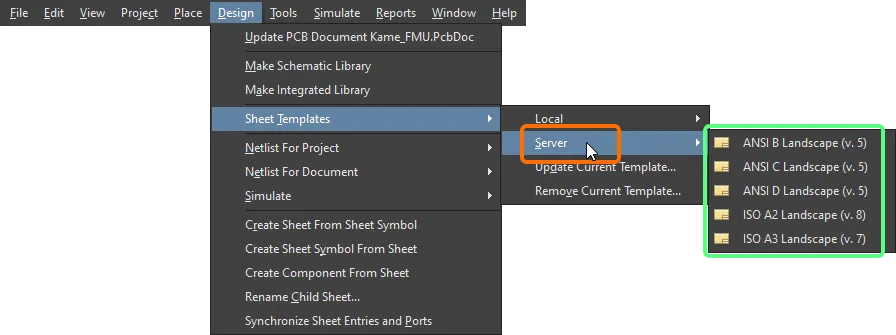
В главном подменю Design » Sheet Templates редактора схем вы можете выбрать другой шаблон — из Workspace или локальный.
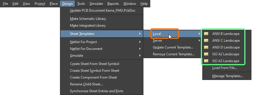
Выберите команду Load From File в подменю Design » Sheet Templates » Local, чтобы найти и выбрать файл шаблона схемы на вашем диске. Выберите команду Manage Templates, чтобы открыть страницу Data Management – Templates page диалога Preferences
Применение шаблона Workspace при использовании конфигурации окружения
Кроме того, шаблон схемы Workspace можно использовать как элемент данных конфигурации в одной или нескольких определенных Environment Configurations. При подключении к Workspace и использовании конфигурации окружения, которая не управляет использованием шаблонов схем, вы можете вручную выбрать ревизию шаблона схемы. Для этого используйте команду Design » Sheet Templates » Set Template from server . Откроется диалог Choose Template , в котором можно просмотреть и выбрать требуемый шаблон в Workspace.
 доступными вам шаблонами схем.")
Используйте команду Set Template from server, чтобы вручную повторно использовать (и переключаться между) доступными вам шаблонами схем.
При необходимости вы также можете использовать локальные шаблоны схем в дополнение к шаблонам из Workspace.
Обновление шаблона
Чтобы обновить шаблон схемы Workspace, который в данный момент используется на активном листе схемы, до последней ревизии связанного элемента шаблона схемы (или чтобы обновить локальный шаблон, в который могли быть внесены какие-либо изменения), используйте кнопку  рядом с раскрывающимся списком Template на панели Document Options Properties либо выберите команду Design » Sheet Templates » Update Current Template в главном меню.
Удаление шаблона с листа схемы
Чтобы удалить текущий используемый шаблон схемы, выберите в главном меню команду Design » Sheet Templates » Remove Current Template. После запуска команды откроется диалог Remove Template Graphics.

Диалог Remove Template Graphics
Используйте этот диалог, чтобы указать, из каких документов будет удалён текущий шаблон: только из текущего документа, из всех документов схемы в текущем (активном) проекте (схемы, которые сейчас закрыты, будут открыты) или из всех открытых документов схемы (независимо от родительского проекта). После выполнения этой команды запись о текущем используемом шаблоне станет пустой.
При удалении текущего шаблона из всех документов схемы в текущем проекте все документы, которые сейчас закрыты, будут открыты по мере выполнения удаления. При удалении текущего шаблона из всех открытых документов схемы он удаляется независимо от проекта, к которому относится документ.
В качестве альтернативы можно прекратить использование шаблона, переключившись в другой режим Formatting and Size (Standard или Custom) на панели Properties.
Параметры уровня документа
Параметры уровня документа можно настроить для каждого документа схемы. Параметры документа задаются на панели Properties , которая доступна, когда на схеме не выделены объекты. На вкладке Parameters панели выполняется добавление, редактирование или удаление параметров схемы. Используйте кнопки над списком параметров, чтобы отображать в списке только параметры, как показано на изображении ниже.
Добавление параметра выполняется нажатием кнопки Add , затем выбором Parameter, , как показано на изображении ниже. В списке появится новый параметр с именем Parameter n. Щёлкните по имени и введите нужное имя параметра. Щёлкните в столбце Value и введите требуемое значение параметра.

Чтобы отредактировать значение параметра, щёлкните ячейку в столбце Value , затем внесите необходимые изменения.
Чтобы удалить параметр, выделите его в списке и нажмите  . В панели будет запрошено подтверждение удаления. Можно выбрать один или несколько параметров в списке, чтобы удалить их за один раз.
Панель Properties
Когда активный документ — это документ схемы (*.SchDoc) и в рабочей области не выбран ни один объект проектирования, панель Properties отображает Document Options.
Панель Document Options Properties также можно открыть двойным щелчком по рамке листа.
Многие параметры/элементы управления этой панели очевидны и не требуют дополнительных пояснений. Те, которые требуют, описаны в следующих разделах.
General Tab
Selection Filter
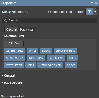
Параметры в этом разделе панели определяют, какие объекты схемы можно выделять в рабочей области.
General

-
Units – быстро проверьте активные единицы измерения в строке состояния, посмотрев на запись Grid в левой части строки. Чтобы переключаться между единицами mils и mm для активного листа схемы, используйте команду View » Toggle Units в главном меню.
-
Visible Grid – используйте значок «глаз», чтобы показать/скрыть сетку в рабочей области.
-
Snap Grid – введите нужный шаг сетки в текстовом поле или используйте сочетание G, чтобы циклически переключаться между различными сетками.
-
Snap Distance – когда курсор находится на расстоянии, не превышающем заданное, от включённой точки привязки объекта (и привязка включена для активного слоя), он будет привязываться к этой точке.
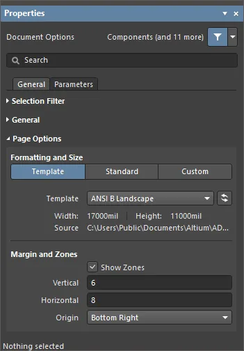
Page Options
Некоторые параметры в этой области не требуют пояснений. Те, которые требуют, описаны ниже.
-
Formatting and Size
-
Template режим – задайте размер и формат страницы, выбрав один из предопределённых шаблонов листа схемы. Шаблон схемы — это документ, содержащий заданные пользователем размер листа, описание рамки и основной надписи и т. п., на который можно ссылаться (связывать) из листа схемы, устраняя необходимость повторно задавать эти общие атрибуты. Список включает локальные шаблоны и шаблоны Workspace, находящиеся в расположении, указанном на странице Data Management – Templates диалога Preferences. Обратите внимание: шаблон листа схемы по умолчанию для новых документов схемы можно задать на этой странице диалога Preferences.
-
Template – используйте раскрывающееся меню, чтобы выбрать шаблон из списка шаблонов Workspace и локальных шаблонов, и при необходимости используйте кнопку  , чтобы обновить шаблон, в который могли быть внесены какие-либо изменения.
-
Margin and Zones – определяет размер графики рамки листа и её зональное деление. Снимите флажок Show Zones, чтобы скрыть зональные деления в графике рамки.
-
Vertical – задайте количество делений (строк) на вертикальном поле листа. Тип буквенно-цифровой маркировки зон задаётся параметром Origin.
-
Horizontal – задайте количество делений (столбцов) на горизонтальном поле листа.
-
Origin – задаёт, из какого угла листа(ов) документа начнутся буквенно-цифровые индикаторы зон по периметру (позиция зоны
A-1 или 1-A).
-
Margin Width – задайте расстояние (в текущих единицах) между краем страницы и каждой из четырёх линий рамки, как показано стрелками, связанными с каждым полем ввода.
Parameters Tab
Parameters
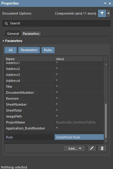
На вкладке Parameters панели Properties перечислены все доступные Parameters и Rules, доступные в текущем документе проекта.
При использовании функциональности
Constraint Manager учтите, что правила, добавленные на панели
Properties, не будут обнаружены и перенесены при обновлении PCB по схеме. Будут перенесены только правила проектирования, определённые в
Constraint Manager.
-
All кнопка – выберите, чтобы просматривать и Parameters, и Rules.
-
Parameters кнопка – выберите, чтобы просматривать только Parameters.
-
Rules кнопка – выберите, чтобы просматривать только Rules.
-
Parameters
-
Name and Value столбцы – список доступных параметров, сгруппированных по типу.
Если один и тот же параметр существует более чем в одном месте (Variant, Document, Project) и у параметра Document нет значения, значение параметра наследуется от параметра с наивысшим приоритетом, у которого значение задано (значение, определённое в документе схемы, переопределяет значение, заданное в параметрах проекта; значение, заданное в варианте, переопределяет значение, заданное в документе схемы). Когда значение параметра Document наследуется (то есть берётся из параметра Variant или Project с тем же именем), оно отображается на панели Properties серым курсивом, что указывает на наследование. Значение параметра Document при необходимости всё равно можно редактировать.
Следующие параметры зарезервированы для внутреннего использования:
-
ConfigurationParameters
-
IsUserConfigurable
Хотя эти параметры не отображаются в списке, добавить пользовательские параметры с такими именами невозможно.
-
Rules
-
Name and Value столбцы – в них перечислены текущие заданные правила и их значения.
-
Add – используйте раскрывающееся меню, чтобы выбрать добавление Parameter или Rule. Выбор добавления нового Rule откроет диалог Choose Design Rule Type для указания типа правила, которое будет использоваться при добавлении параметра как правила к поддерживаемому объекту проектирования в домене схемы или к документу схемы.
-
 – доступно только когда выбрано правило. Нажмите, чтобы открыть диалог Edit PCB Rule и отредактировать выбранное правило.
-
 – нажмите, чтобы удалить текущий выбранный параметр или правило.
Когда выбран объект проектирования, панель отображает параметры, специфичные для типа этого объекта. В следующей таблице перечислены типы объектов, доступные для размещения на листе схемы. Нажмите ссылку, чтобы перейти на страницу свойств этого объекта.

 Локализовано с помощью ИИ