为制造做准备
The final phase of the design cycle is to generate the output files needed to manufacture the product. To do this, you need to generate a variety of output files in a variety of formats. As the designer, you have the choice of individually configuring and generating the outputs via the schematic and PCB editor, or alternatively, you can add all of the required outputs into an OutputJob and then generate them as part of the project release process.


The ultimate objective is to manufacture the product – for example, fabricate and assemble a PCB.
Preparing Manufacturing Data with Output Jobs
You can individually configure and generate the outputs directly through the File and Reports menus of relevant editors. In this case, the outputs are generated directly when you click OK in the associated settings dialog and written to the location specified in the Output Path field in the Options tab of the Project Options dialog.
However, Output Job files facilitate streamlined preparation of outputs for your designs and their subsequent generation using the high-integrity project release process. An Output Job, or 'OutJob' for short, is essentially a pre-configured set of outputs that stores settings for these outputs and defines where the generated outputs will be written.
To add a new OutJob to your design project, right-click the project's entry in the Projects panel and select Add New to Project » Output Job File command from the context menu. A default OutJob will open in the design space.

A newly created OutJob will be the active document in the design space.
Numerous output types for different purposes can be added and configured using the left-hand side of the OutJob. Outputs are gathered into functional categories, such as Assembly Outputs, Fabrication Outputs, and Report Outputs.
Add a new output of the required type by clicking on the appropriate Add New <Type> Output text at the bottom of a category and choosing the required output type from the pop-up menu. A sub-menu for an output type entry is provided from which you can specify the data source, i.e. which source document(s) to be used when the output is generated. Any number of outputs can be added.

For specific output types, options are available to configure an added output by right-clicking the output in the list and selecting the Configure command from the context menu. The associated configuration dialog to define options for the output will open. For example, the Gerber X2 Setup dialog will open for a Gerber X2 Setup output.

Configure an output as required in the associated setup dialog.
To define where and in which format an output is to be generated, output containers and print jobs are used. Outputs can be written (where applicable) to three types of output containers – PDF, video, or folder structure (a specific format of output file such as a Gerber file). Certain outputs can also be sent directly to a printing device as hard copy by adding and configuring a print job.
A new OutJob contains one output container of each type and a print job for the default printer. Their entries are displayed on the right-hand side of the OutJob. If required, a new output container or print job can be added by clicking the Add New Output Container control and selecting the required container type or clicking the Add New Print Job control and selecting the required printer, respectively.

Add new output containers and/or print jobs as required.
To specify which outputs are to be generated using which output container / print job, select a container/job and then check the Enabled flag for each required output in the output list. Once enabled, a green line will connect an output to the selected output container / print job. Outputs can be mapped to individual or shared output containers / print jobs.

Map added outputs to the corresponding output containers and print jobs using the Enabled flags.
To configure an output container / print job, select its entry and click the Change control. The associated dialog will open – for example, when a folder structure output container is selected, the Folder Structure settings dialog will open where you can configure the output location of the file(s) to be generated and further options related to file generation.

Configure the settings of an output container / print job in the associated dialog.
The configured outputs in an OutJob can be generated either from within the OutJob directly or, for a PCB design project, as part of the high integrity project release process. To generate outputs associated with a output container / print job directly from the OutJob, select the container/job and click the Generate content or Print control, respectively.

You can generate or print outputs directly from the OutJob.
Board Design Release
Using the board design release process, you can simultaneously generate all manufacturing data configured in OutJob files of your PCB project. This process has a number of advantages compared with generating outputs individually or directly from OutJobs, including an ability to validate the design as an integral part of the release process and avoiding manual intervention during the release process. Also, when releasing to the connected Workspace, tight integration with the Workspace's version control is provided.
To start the release of a project, right-click its entry in the Projects panel and select the Project Releaser command from the context menu. The Release view will open as a separate tab.

Access the Release view – the user interface to the Project Releaser.
The release process is a staged flow, with the entries on the left-hand side of the Release view showing you which stage you are currently at.
On the initial stage of the release process, you can click the Options button at the bottom-left of the view to access the Project Release Options dialog and configure the options of the release process as required. The options include selecting the release target (Workspace, folder, or zip file) and assignment of OutJobs.

Configure release options in the Project Release Options dialog.
Depending on the selected release target, the stages of the release process differ slightly. A release to a connected Workspace is shown below as an example.
|
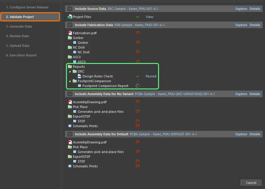
At the Configure Server Release stage, you can specify the type(s) of data you wish to generate: source data (a snapshot of the source design, always included in the release), fabrication data, and assembly data. The number of assembly data sets will correspond to the base (non-varied) design and all detected design variants. When ready, click the Prepare button at the bottom-right of the view to proceed. If any issues are found, you will be offered solutions with which to resolve them. The Validate Project stage is run automatically when one or more validation-type reports, such as a Design Rule Check report, are detected in assigned OutJob file(s), and the associated validation outputs are run. The release will fail if any validation checks are not passed successfully. The Generate Data stage is run automatically when the previous stage completes without issues. At this stage, all other outputs defined in the assigned OutJob file(s) are run to generate the data to be released. With all validation checks passed and output data generated, the Review Data stage allows you to review the generated data. Proceed with the release by clicking the Release button at the bottom-right of the view and confirming the release in the dialog that appears. After confirming the release in the previous stage, the Upload Data stage is automatically entered. It presents the progress of data upload. The final Execution Report stage of the process provides a summary of the release. With your project released, you can close the Release view by clicking the Close button at the bottom-right of the view. |