Supporting your need to work with design files in other formats and from other tools, Altium Designer provides an importer for Autodesk® EAGLE™ (Easily Applicable Graphical Layout Editor) design files and libraries (*.sch, *.brd, *.lbr).
To access EAGLE import capabilities in Altium Designer, the EAGLE feature must be enabled for your installation of Altium Designer. This feature is enabled in Altium Designer by default. It can be enabled/disabled after installation.
For more information about changing installed core functionality, refer to the Installing & Managing page (Altium Designer Develop, Altium Designer Agile, Altium Designer).
For information regarding Migrating from Autodesk EAGLE to Altium Designer, click here.
Version Support
The EAGLE Importer is able to import XML-format EAGLE design files saved with EAGLE versions 6.4 through to 9.4. These are XML-format in nature; EAGLE binary-format design files cannot be imported directly using the EAGLE Importer. For these older, binary version design files, it is advised to save them in this later (XML) format through your EAGLE software before attempting to import into the software.
Accessing and Running the EAGLE Importer
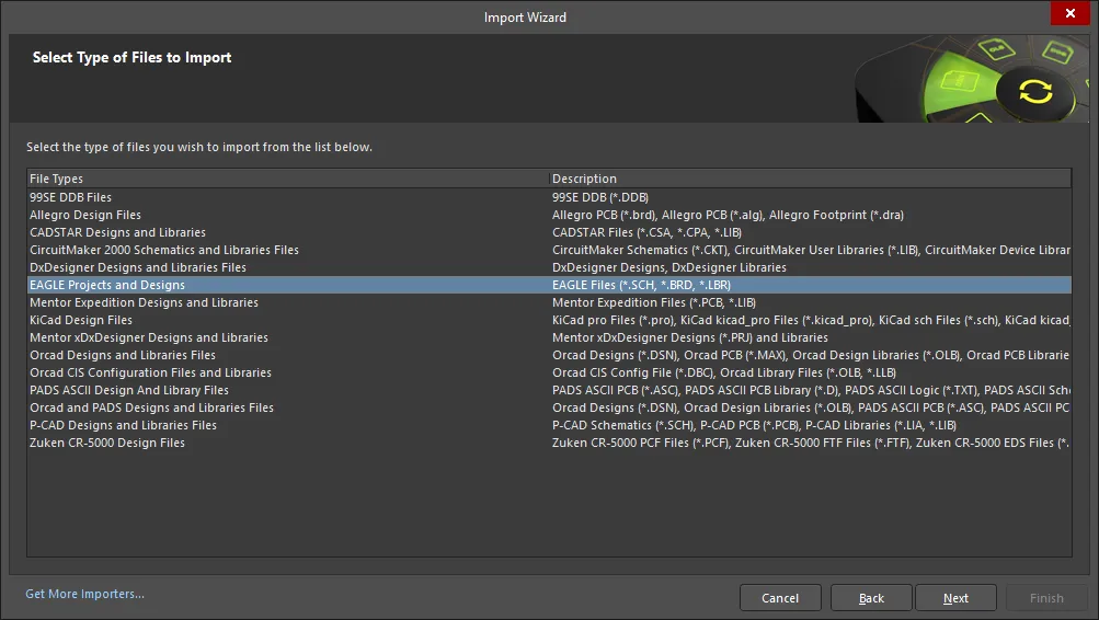
Import is performed using the Import Wizard (File » Import Wizard). Select the EAGLE Projects and Designs entry to gain access to the EAGLE Import Wizard then click Next.
 Access the EAGLE Import Wizard through the Import Wizard dialog.
The EAGLE Import Wizard will guide you through the steps involved when importing these types of files including:
-
Specifying which EAGLE design archives (*.BRD, *.SCH) to include in the process.
-
Specifying which EAGLE library files (*.LBR) to include in the process.
-
Setting options to control the reports manager.
-
Setting options related to project structure.
-
Specifying the location of the output directory in which to import the files
Schematic hierarchy is supported.
You have full control over where the generated Altium Designer project(s) and associated documents are to be located by specifying an output directory.
The proposed output structure is also displayed so you can see exactly what you will be getting with the import. If all is as required, proceed with the import by clicking Next. If you need to change anything, click the Back button. If you want to cancel out of the import, click Cancel.

Specify which EAGLE design files and/or libraries are to be imported and other options as required.
Check the output directory and proposed structure, before proceeding with the import process.
The Reporting Options page of the importer is used to review and edit the layer mapping for each Eagle PCB. Default mapping is provided to build the layer mapping for each PCB. Layer mapping can be customized for each of your designs to be imported.
The Eagle Layer Name, Eagle Layer Type, Altium Layer Type, and Altium Layer Name are listed in the grid region. Click on the  icon on the right-hand side of each region to filter the displayed list of that region.
If desired, you can edit the layer mapping for any or all Eagle Import PCB designs or library files on this page of the Wizard. To group by a column, drag the column header into the area at the top of the table specified.
Right-clicking in the grid region provides you with a sub-menu where you can:
-
Load Mapping from file - select to open the Load Configuration dialog to load the desired mapping files.
-
Save Mapping from file - select to open the Choose File to Save Layer Mapping dialog and choose the path in which to save the layer mapping.
On the Output Projects page of the importer, the Schematic settings only become available if you attach a .sch file on the Importing EAGLE Design Files page. The PCB Settings on the Output Projects page is only available when a .brd file is attached on the Importing EAGLE Design Files page. These files determine which options may be toggled. The options include choosing to log all errors, warning, and events. For .brd files, you may choose to generate PCB settings through a 3D body and by layers. Schematics settings vary greatly, allowing you to choose aspects of the files to recognize, hide, and ignore. Library settings allow you to choose to either add the libraries being imported to the PCB project if one exists or to not add the libraries.
By default, the output directory will target the location of the original source EAGLE design/library files.

Once the import process completes, click Finish in the Import Wizard dialog to close it. The result of the import can be seen in the Projects panel and can be summarized as follows:
-
An Altium Designer PCB Project (
*.PrjPcb) is created per EAGLE .sch, .brd and .lbr involved in the import.
-
An EAGLE schematic design archive (
*.sch) is imported into an Altium Designer Schematic document (*.SchDoc).
-
An EAGLE PCB design archive (
*.brd) is imported into an Altium Designer PCB document (*.PcbDoc).
-
An EAGLE library (
*.lbr) is imported as Altium Designer Schematic Library (*.SchLib) and PCB Library (*.PcbLib) documents. In addition, an integrated Library (*.IntLib) is compiled based on these source libraries.
-
A Log file (
*.log) is generated for each imported file, which shows the results of analysis on the original EAGLE file, as well as any errors and warnings (if enabled for inclusion).
Import Wizard - EAGLE Projects and Designs
EAGLE Projects and Designs
Importing EAGLE Design Files

Click Add to choose which EAGLE design archives (BRD and/or SCH) to include in the process. You can delete a selected file by clicking Remove.
Importing EAGLE Library Files
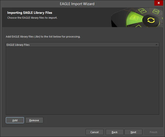
Click Add to choose which EAGLE library files (LBR) to include in the process. You can delete a selected file by clicking Remove.
A progress window will open and close quickly before the next page of the Wizard appears.
Reporting Options
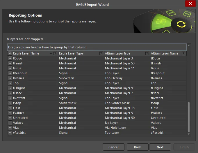
Use the Reporting Options page to control the reports manager.
Output Projects
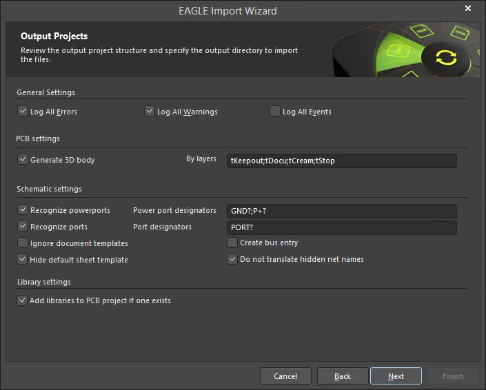
Use the Output Projects page to review the output project structure and specify the output directory to import the files.
Under General Settings, enable the desired options: Log All Errors, Log All Warnings, Log All Events.
-
PCB Settings
-
Generate 3D body – enable to generate a 3D body.
-
By layers – use to denote the layer order, separated by a semi-colon (;).
-
Schematic Settings
-
Recognize powerports – enable to recognize schematic powerports. Ensure that the default values in the Power port designators textbox are correct. If not, enter correct designators directly in the textbox.
-
Recognize ports – enable to recognize standard ports. Ensure that the default values in the Port designators textbox are correct. If not, enter correct designators directly in the textbox.
If power ports in your EAGLE designs are named using the format P+?, then accepting the default setting for the recognition of standard ports (with Port designators set to PORT?;P+?) will result in those power ports being incorrectly translated as standard ports, leading to shorts in the circuitry. In such a case, change the Port designators setting to "PORT?".
-
Ignore document templates – enable to ignore any document templates.
-
Hide default sheet template – enable to hide the default sheet template.
-
Create bus entry – enable to create a bus entry.
-
Do not translate hidden net name – enable to not translate hidden net name(s).
-
Library Settings
-
Add libraries to PCB project if one exists – enable to add libraries to the project.
Executing Import Process

You have full control over where the generated Altium Designer project(s) and associated documents are to be located by specifying the Output Directory. Use the Browse Folder icon to search for and select the desired location for the output.
By default, the output directory will target the location of the original source EAGLE design/library files.
The proposed Output Structure is also displayed so you can see exactly the files and structure tree that will be generated. If everything is correct, proceed with the import by clicking Next.
Executing Import Process

The Executing Import Process page displays the document that is currently being processed with a green bar to show the progress of the import.
Closing the Wizard

The EAGLE Import Wizard has completed. Click Finish to close the Wizard.
Imported EAGLE files:
The result of the import can be seen in the Projects panel and can be summarized as follows:
-
An Altium Designer PCB Project (*.PrjPcb) is created per EAGLE .sch, .pcb and .lbr involved in the import.
-
An EAGLE schematic design archive (*.sch) is imported into an Altium Designer Schematic document (*.SchDoc).
-
An EAGLE PCB design archive (*.pcb) is imported into an Altium Designer PCB document (*.PcbDoc).
-
An EAGLE library (*.lbr) is imported as Altium Designer Schematic (*.SchLib) and PCB (*.PcbLib) library documents. In addition, an integrated Library (*.IntLib) is compiled based on these source libraries.
-
A Log file (*.log) is generated for each imported file that shows the results of analysis on the original EAGLE file as well as any errors and warnings (if enabled for inclusion).
Post-Import Considerations
After importing your EAGLE design files, it is fairly common to check and possibly change a few things. The following is an example of a post-import procedure that may be undertaken. This is by no means an exhaustive, or indeed mandatory requirement, but more of a thought-provoking aid for possible items to consider post-import:
-
When schematic and PCB files are present and imported into separate projects, move (or copy) the imported design files into a single Altium Designer PCB project.
-
Check component links (again, when both schematic source and PCB board have been imported). From the imported PCB for the design, use the Project » Component Links command. Use the subsequent Edit Component Links dialog to match (link) schematic and PCB components.
-
Check the Design Rules using the PCB Rules and Constraints Editor dialog (Design » Rules) fixing any that are not quite targeting the intended objects, and simplifying where ever possible (especially Clearance and Width rules).
-
If not already present on import, make a PCB Library from the PCB design (Design » Make PCB Library), fix any parts as needed to the required standard for your company, and also add 3D models.
-
Update the PCB Design from the update PCB Library (if applicable).
-
Run a DRC (Tools » Design Rule Check) using the Design Rule Checker dialog and fix any errors.
-
Clean up any imported polygons into larger pours with associated rules.
-
Add a keepout boundary to the board.
