PCB 설계에서 Keepout 은 레이아웃에서 구리 개체가 교차할 수 없도록 배치된 사용자 정의 영역 또는 둘레입니다. 일반적으로 Polygon Pour 및 대화형 라우팅과 같은 자동화된 구리 배치 작업에서 사용되는 영역을 제어하기 위해 포함되며, Keepout은 수동으로 구리 개체를 배치할 때 잘못된 위치를 나타내기도 합니다.
디자인 레이아웃 중에 지정된 '이동 금지' 영역으로서 Keepout 객체는 기존 클리어런스 제약 규칙을 사용하여 라우팅을 제어하고 배치 위반을 감지하지만, 다른 배치 객체와 달리 Net에 할당할 수 없으며 생성된 출력이나 인쇄물에는 표시되지 않습니다. 가장 간단한 의미에서 Keepout은 글로벌 클리어런스 규칙에 지정된 대로 다른 구리 개체가 해당 영역과 교차하지 못하도록 하는 '간섭' 개체 역할을 합니다. Keepout Object는 Keepout 레이어(모든 신호 레이어에 적용)에 배치하거나 신호 레이어(해당 레이어에 있는 Object에만 적용)에 배치할 수 있습니다.
알티움 디자이너는 Object Specific Keepouts 을 지원하여 Keepout을 생성하고 적용할 수 있습니다. 배치된 Keepout Object는 트랙, 구리 영역, 비아, 패드 등 어떤 유형의 Object에 적용할지 지정하도록 구성할 수 있어 Keepout의 유연성과 효과가 크게 향상됩니다.
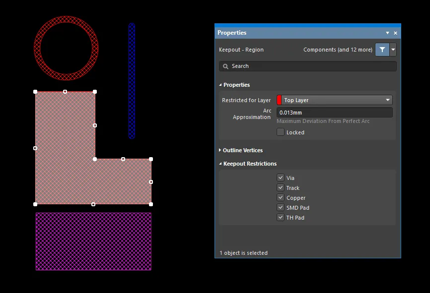
PCB 설계에 배치된 다양한 유형의 Keepout Object.
PCB 및 PCB 라이브러리 Editor에서 Keepout Object는 크로스 해칭으로 표시됩니다. Keepout 레이어에 배치된 Keepout 객체(즉, 모든 신호 레이어에 적용됨)는 Keepout 레이어 색상으로 표시되는 반면, 특정 신호 레이어에 배치된 Keepout(즉, 해당 신호 레이어에만 적용됨)은 해당 신호 레이어의 색상으로 표시됩니다.
Keepout은 라우팅할 수 없는 보드 영역(예: 전기적으로 민감하거나 고전압 영역), 기준점 및 테스트 포인트와 같이 특별히 노출된 구리 위치 또는 기계적으로 호환되지 않는 영역(예: 실장 구멍 또는 PCB의 모서리)을 정의하는 데 이상적입니다. Object별 Keepout의 구성 가능한 특성으로 인해 특정 Keepout Restrictions 이 할당된 경우 다른 Object 위에 배치할 수도 있습니다. 예를 들어 비아만 제한하도록 설정하면 기존 구리 영역(예: Polygon Pour) 위에 Keepout을 배치하여 자동화된 비아 스티칭의 범위를 제어할 수 있습니다.
Object별 Keepout은 PCB Editor 및 PCB 라이브러리 Editor에서 배치할 수 있습니다.
PCB Keepout Object 배치 및 편집에 대한 자세한 내용은 아래 접을 수 있는 섹션을 참조하십시오:
Track Keepout

배치된 트랙 Keepout
트랙은 원시적인 디자인 객체입니다. 디자인 작업에 사용되는 표준 트랙뿐만 아니라 트랙 Keepout이라고 하는 두 번째 유형의 트랙도 사용할 수 있습니다. 트랙 Keepout은 레이어별 Keepout 객체 또는 전체 레이어 Keepout으로 배치하여 배치 또는 라우팅 장벽과 같은 역할을 할 수 있습니다. 표준 트랙과 트랙 Keepout의 차이점은 거버 또는 ODB++와 같은 레이어별 Keepout 유형 채우기는 출력 생성에 포함되지 않는다는 점입니다. Keepout 영역은 Keepout 색상의 Outline으로 식별할 수 있습니다.
Keepout 트랙은 신호 레이어 또는 Keepout 레이어에만 배치할 수 있습니다.
트랙 Keepout 배치 명령을 실행하면 커서가 십자선으로 바뀌고 트랙 Keepout 배치 모드로 들어갑니다. 배치는 다음과 같은 일련의 작업을 수행하여 이루어집니다:
-
Enter 을 클릭하거나 눌러 첫 번째 트랙 Keepout 세그먼트의 시작 지점을 고정합니다.
-
커서를 이동하여 트랙 Keepout 세그먼트를 정의한 다음 Enter 을 클릭하거나 눌러 이 첫 번째 세그먼트의 끝점을 다음 연결된 세그먼트의 시작점이기도 한 곳에 고정합니다.
-
커서를 계속 위치시킨 다음 Enter 을 클릭하거나 눌러 일련의 연결된 트랙 유지 세그먼트를 정의하는 일련의 꼭지점을 고정합니다.
-
마우스 오른쪽 버튼을 클릭하거나 Esc 을 눌러 현재 연결된 일련의 트랙 Keepout 세그먼트를 종료합니다.
배치 중에 수행할 수 있는 추가 작업은 다음과 같습니다:
-
숫자 키패드에서 * 키를 눌러 사용 가능한 신호 레이어를 순환합니다. 또는 Shift+Ctrl+Wheel Roll 조합을 사용하여 라우팅 레이어를 이동하면 마우스 휠의 각 노치가 사용 가능한 다음(또는 이전) 신호 레이어로 이동합니다.
-
숫자 키패드에서 + 및 - 키를 누르면 현재 디자인에 표시된 모든 레이어를 앞뒤로 순환할 수 있습니다.
Keepout 트랙 세그먼트를 배치하는 동안 5가지 코너 모드를 사용할 수 있으며, 이 중 4개 모드에는 코너 방향 하위 모드도 있습니다. 배치 중
-
Shift+Spacebar 을 눌러 사용 가능한 5가지 코너 모드를 순환합니다.
-
Spacebar 을 눌러 두 개의 코너 방향 하위 모드 사이를 전환합니다.
-
호 모서리 모드에서 , 또는 . 키를 길게 눌러 호를 축소하거나 확대합니다. Shift 키를 길게 누르면 호 크기 조정 속도가 빨라집니다.
-
1 단축키를 누르면 클릭당 하나의 세그먼트 배치 또는 클릭당 두 개의 세그먼트 배치 간에 전환할 수 있습니다. 첫 번째 모드에서는 속이 빈 트랙 세그먼트를 룩어헤드 세그먼트라고 합니다.
-
Backspace 키를 눌러 마지막 꼭지점을 제거합니다.
그래픽 편집 방법을 사용하면 디자인 공간에서 배치된 트랙 Keepout 개체를 직접 선택하고 크기, 모양 또는 위치를 그래픽으로 변경할 수 있습니다.
트랙 Keepout을 선택하면 다음과 같은 편집 핸들을 사용할 수 있습니다:

-
트랙의 끝점을 재배치하려면 끝 핸들을 클릭합니다.
-
가운데 핸들을 클릭하고 끌어서 트랙의 모양을 변경합니다.
Track Keepout Properties

Properties 패널의 Keepout - Track 모드입니다.
위치
-
(X/Y)
-
X (첫 번째 필드) - 현재 원점을 기준으로 한 트랙 Keepout 기준점의 현재 X(수평) 좌표입니다. 트랙 Keepout의 X 위치를 변경하려면 편집을 클릭합니다. 값은 미터법 또는 영국식으로 입력할 수 있으며, 현재 기본 단위가 아닌 값을 입력할 때는 단위를 포함해야 합니다.
-
Y (두 번째 필드) - 현재 원점을 기준으로 한 트랙 Keepout 기준점의 현재 Y(수직) 좌표입니다. 트랙 Keepout의 Y 위치를 변경하려면 편집합니다. 값은 미터법 또는 영국식 단위로 입력할 수 있으며, 현재 기본값이 아닌 단위를 입력할 때는 단위를 포함해야 합니다.
속성
-
Component - 이 필드는 선택한 트랙 Keepout이 PCB 컴포넌트의 구성 부분인 경우에만 PCB 편집기에 표시되며 상위 PCB 컴포넌트의 지정자를 표시합니다. 클릭 가능한 Component 링크를 선택하면 상위 컴포넌트에 대한 속성 패널의 컴포넌트 모드가 열립니다.
-
Restricted for Layer - 드롭다운을 사용하여 제한된 레이어를 선택합니다.
-
Width - 트랙 Keepout의 현재 너비를 표시합니다. 이 필드를 편집하여 0.001밀리~ 10000밀리 범위 내에서 트랙 Keepout 폭을 변경합니다.
-
Start (X/Y) - 현재 원점을 기준으로 트랙 키아웃 시작점의 현재 X/Y 좌표를 표시합니다.
-
End (X/Y) - 현재 원점을 기준으로 트랙 키아웃 종료 지점의 현재 X/Y 좌표를 표시합니다.
-
Length - 트랙 키아웃의 현재 길이를 표시합니다. 이 필드를 편집하여 0.001mil ~ 10000mil 범위 내에서 트랙 키아웃 길이를 변경할 수 있습니다.
값은 mm 또는 mil 단위로 정의할 수 있습니다. 현재 단위가 아닌 다른 단위로 값을 입력할 때는 값에 mm 또는 mil 접미사를 추가합니다.
Keepout 제한
이 영역을 사용하여 Keepout으로 제한할 개체 유형을 선택합니다. Object 유형을 선택 해제하면 해당 클리어런스 규칙을 적용하지 않음으로써 해당 Object 유형의 위반을 허용(차단되지 않음)합니다. 선택할 수 있는 항목은 다음과 같습니다:
-
Via
-
Track
-
Copper
-
SMD Pad
-
TH Pad
Arc Keepout
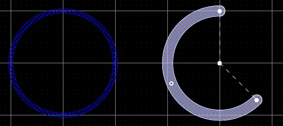
두 개의 하단 레이어 Keepout 호: 왼쪽은 전체 원 Keepout 호, 오른쪽은 편집을 위해 선택한 Keepout 호입니다.
아크 Keepout은 원시적인 디자인 개체입니다. 기본적으로 모든 레이어에 배치할 수 있는 원형 트랙 세그먼트입니다. 컴포넌트 Outline 또는 곡선 경로 정의와 같은 디자인 작업에 사용되는 표준 호뿐만 아니라 Keepout 호라고 하는 두 번째 유형의 호를 사용할 수 있습니다. Keepout 아크는 신호 레이어에 배치하여 레이어별 배리어 또는 금지 영역을 만들 수 있습니다. 또한 모든 신호 레이어에 적용되는 Keepout 레이어에 배치할 수도 있습니다. 표준 아크와 Keepout 아크의 차이점은 거버 또는 ODB++와 같은 레이어별 Keepout 유형 아크는 출력 생성에 포함되지 않는다는 것입니다. Keepout 호는 Keepout 색상의 Outline으로 식별할 수 있습니다.
Keepout 호는 신호 레이어 또는 Keepout 레이어에만 배치할 수 있습니다.
호를 배치하는 방법은 호출하기로 선택한 특정 배치 방법에 따라 다릅니다. 네 가지 호 배치 방법이 지원됩니다:
-
Place arc by center - 이 방법을 사용하면 호 중심을 시작점으로 사용하여 호 개체를 배치할 수 있습니다.
-
Place arc by edge - 이 방법을 사용하면 호의 가장자리를 시작점으로 사용하여 호 개체를 배치할 수 있습니다. 호 각도는 90°로 고정됩니다.
-
Place arc by edge (any angle) - 이 방법을 사용하면 호의 가장자리를 시작점으로 사용하여 호 개체를 배치할 수 있습니다. 호의 각도는 임의의 값이 될 수 있습니다.
-
Place full circle arc - 이 방법을 사용하면 360°(전체 원) 호를 배치할 수 있습니다.
Placing a Keepout Arc Starting at the Center
명령을 실행하면 커서가 십자 화살표로 바뀌고 Keepout 호 배치 모드로 들어갑니다. 다음과 같은 일련의 작업을 수행하여 배치합니다:
-
Enter 을 클릭하거나 눌러 Keepout 호의 중심점을 고정합니다.
-
커서를 이동하여 Keepout 호의 반지름을 조정한 다음 Enter 을 클릭하거나 눌러 설정합니다.
-
커서를 이동하여 Keepout 호의 시작점을 조정한 다음 Enter 을 클릭하거나 눌러 고정합니다.
-
커서를 이동하여 Keepout 호의 끝점 위치를 변경한 다음 Enter 을 클릭하거나 눌러 고정하고 Keepout 호의 배치를 완료합니다.
-
Keepout 호를 계속 배치하거나 마우스 오른쪽 버튼을 클릭하거나 Esc 을 눌러 배치 모드를 종료합니다.
Placing a Keepout Arc Starting at the Edge
명령을 실행하면 커서가 십자 화살표로 바뀌고 Keepout 호 배치 모드로 들어갑니다. 다음과 같은 일련의 작업을 수행하여 배치합니다:
-
Enter 을 클릭하거나 눌러 Keepout 호의 시작점을 고정합니다.
-
커서를 이동하여 Keepout 호의 끝점 위치를 변경한 다음 Enter 을 클릭하거나 눌러 고정하고 Keepout 호 배치를 완료합니다.
-
Keepout 호를 계속 배치하거나 마우스 오른쪽 버튼을 클릭하거나 Esc 을 눌러 배치 모드를 종료합니다.
Placing a Keepout Arc Starting at the Edge (any angle)
명령을 실행하면 커서가 십자 화살표로 바뀌고 Keepout 호 배치 모드로 들어갑니다. 다음과 같은 일련의 작업을 수행하여 배치합니다:
-
Enter 을 클릭하거나 눌러 Keepout 호의 시작점을 고정합니다.
-
커서를 이동하여 Keepout 호의 반지름을 조정한 다음 Enter 을 클릭하거나 눌러 중심점을 고정합니다.
-
커서를 이동하여 Keepout 호의 끝점 위치를 변경한 다음 Enter 을 클릭하거나 눌러 고정하고 Keepout 호의 배치를 완료합니다.
-
Keepout 호를 계속 배치하거나 마우스 오른쪽 버튼을 클릭하거나 Esc 을 눌러 배치 모드를 종료합니다.
Placing a Full Circle Keepout Arc
명령을 실행하면 커서가 십자선으로 바뀌고 Keepout 호 배치 모드로 들어갑니다. 다음과 같은 일련의 작업을 수행하여 배치합니다:
-
Enter 을 클릭하거나 눌러 Keepout 호의 중심점을 고정합니다.
-
커서를 이동하여 Keepout 호의 반경을 조정한 다음 Enter 을 클릭하거나 눌러 설정하고 Keepout 호 배치를 완료합니다.
-
Keepout 호를 계속 배치하거나 마우스 오른쪽 버튼을 클릭하거나 Esc 을 눌러 배치 모드를 종료합니다.
모든 방법(전체 원 호 제외)의 경우, Keepout 호의 끝점을 정의하기 전에 Spacebar 을(를) 눌러 호를 반대 방향으로 렌더링합니다.
그래픽 편집 방법을 사용하면 디자인 공간에서 배치된 호 개체를 직접 선택하고 크기, 모양 또는 위치를 그래픽으로 변경할 수 있습니다.
Keepout 호 개체를 선택하면 다음과 같은 편집 핸들을 사용할 수 있습니다:
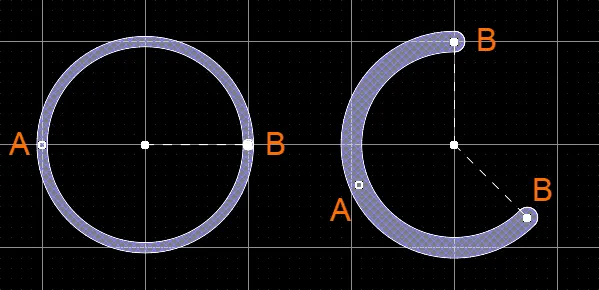
선택한 Keepout 호
-
A 을 클릭하고 드래그하여 반경을 조정합니다.
-
B 을 클릭하고 끌어서 끝점(시작 및 끝 각도)을 조정합니다.
-
편집 핸들에서 떨어진 호의 아무 곳이나 클릭한 다음 드래그하여 위치를 변경합니다. 또는 호의 중심점을 클릭하고 드래그합니다. 드래그하는 동안 호를 회전하거나 미러링할 수 있습니다:
-
호를 시계 반대 방향으로 회전하려면 Spacebar 을, 시계 방향으로 회전하려면 Shift+Spacebar 을 누르세요. 회전은 Preferences 대화 상자의 PCB 편집기 - 일반 페이지에 정의된 Rotation Step 값에 따릅니다.
-
X 또는 Y 키를 눌러 각각 X축 또는 Y축을 따라 호를 미러링합니다.
Arc Keepout Properties
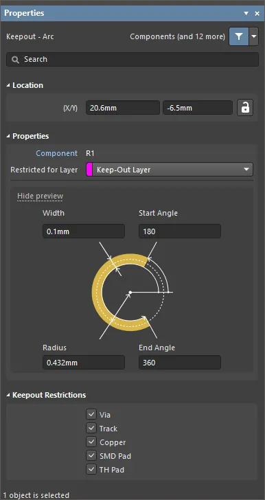
Properties 패널의 Keepout - Arc 모드입니다.
위치
-
(X/Y)
-
X (첫 번째 필드) - 현재 디자인 공간 원점을 기준으로 한 아크 키아웃의 기준점의 현재 X(수평) 좌표입니다. 아크 키아웃의 X 위치를 변경하려면 편집을 클릭합니다. 값은 미터법 또는 영국식으로 입력할 수 있으며, 현재 기본 단위가 아닌 값을 입력할 때는 단위를 포함해야 합니다.
-
Y (두 번째 필드) - 현재 원점을 기준으로 한 아크 Keepout 기준점의 현재 Y(수직) 좌표입니다. 아크 키아웃의 Y 위치를 변경하려면 편집합니다. 값은 미터법 또는 영국식 단위로 입력할 수 있으며, 현재 기본값이 아닌 단위를 입력할 때는 단위를 포함해야 합니다.
속성
-
Component - 이 필드는 선택한 아크 Keepout이 PCB 컴포넌트의 구성 부품인 경우에만 PCB 편집기에 표시되며 상위 PCB 컴포넌트의 지정자를 표시합니다. 클릭 가능한 Component 링크를 선택하면 상위 컴포넌트에 대한 속성 패널의 컴포넌트 모드가 열립니다.
-
Restricted Layer - 이 필드에는 현재 아크 Keepout이 할당된 제한된 레이어가 표시됩니다. 레이어를 변경하려면 필드를 클릭하고 드롭다운 목록에서 레이어를 선택합니다.
-
Width - 이 필드에는 아크 Keepout 선의 너비가 표시됩니다. 필요한 경우 너비에 다른 값을 입력합니다.
-
Radius - 이 필드에는 중심점부터 호 유지선의 중심까지 측정된 호의 반지름이 표시됩니다. 필요한 경우 반경에 다른 값을 입력합니다.
-
Start Angle - 이 필드에는 첫 번째 사분면(평면 지오메트리)의 X축에서 측정한 아크 Keepout의 시작 각도가 표시됩니다. 필요한 경우 시작 각도에 대해 다른 값을 입력합니다.
-
End Angle - 이 필드에는 아크 Keepout의 끝 각도가 표시됩니다. 필요한 경우 끝 각도에 대해 다른 값을 입력합니다.
값은 mm 또는 mil 단위로 정의할 수 있습니다. 현재 단위가 아닌 다른 단위로 값을 입력할 때는 값에 mm 또는 mil 접미사를 추가합니다.
Keepout 제한
이 영역을 사용하여 Keepout으로 제한할 개체 유형을 선택합니다. 개체 유형을 선택 해제하면 해당 클리어런스 규칙을 적용하지 않음으로써 해당 개체 유형의 위반을 허용(차단되지 않음)하게 됩니다. 선택할 수 있는 항목은 다음과 같습니다:
-
Via
-
Track
-
Copper
-
SMD Pad
-
TH Pad
Region Keepout

지역 유지
영역 Keepout은 기본 디자인 객체입니다. 디자인 작업에 사용되는 표준 영역뿐만 아니라 영역 Keepout이라고 하는 두 번째 유형의 영역을 사용할 수 있습니다. 영역 Keepout은 레이어별 Keepout Object 또는 전체 레이어 Keepout으로 배치하여 배치 또는 라우팅 배리어 역할을 할 수 있습니다. 표준 영역과 Keepout 영역의 차이점은 거버 또는 ODB++와 같은 레이어별 Keepout 유형 채우기는 출력 생성에 포함되지 않는다는 점입니다. Keepout 영역은 Keepout 색상의 Outline으로 식별할 수 있습니다.
영역 Keepout은 신호 레이어 또는 Keepout 레이어에만 배치할 수 있습니다.
영역 Keepout 배치 명령(Place » Keepout » Solid Region )을 실행하면 커서가 십자 표시로 바뀌고 영역 Keepout 배치 모드로 들어갑니다. 배치는 다음과 같은 일련의 작업을 수행하여 이루어집니다:
-
커서를 위치시킨 다음 클릭하여 영역 Keepout의 시작 버텍스를 고정합니다.
-
두 번째 버텍스를 배치할 준비가 되면 커서를 이동합니다. 기본 동작은 클릭할 때마다 두 개의 가장자리를 배치하고 그 사이에 사용자 정의 모서리 모양을 배치하는 것입니다.
-
마우스를 계속 이동하고 클릭하여 정점을 추가로 배치합니다.
-
마지막 정점을 배치한 후 마우스 오른쪽 버튼을 클릭하거나 Esc 을 눌러 영역 유지 배치를 닫고 완료합니다. 소프트웨어가 시작점과 배치한 최종 점을 연결하여 도형을 자동으로 완성하므로 영역을 수동으로 닫을 필요가 없습니다.
-
계속해서 영역을 더 배치하거나 마우스 오른쪽 버튼을 클릭하거나 Esc 을 눌러 배치 모드를 종료합니다.
그래픽 편집 방법을 사용하면 디자인 공간에서 배치된 개체를 직접 선택하고 크기, 모양 또는 위치를 그래픽으로 변경할 수 있습니다.
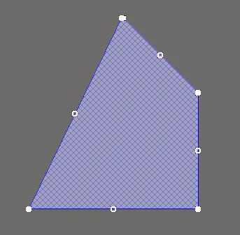
선택한 영역 유지
Move Region Vertices
영역 Keepout에는 영역의 모양을 편집할 수 있는 두 개의 점, 즉 '핸들'이 포함되어 있습니다.
-
Full Handles - 지역 Keepout의 모서리에 위치합니다.
-
Empty Handles - 전체 핸들에 의해 생성된 세그먼트의 중앙에 위치합니다.
각 모서리 또는 각 가장자리의 중앙에 위치한 이러한 핸들 또는 정점을 이동하여 기존 영역 유지의 모양을 변경할 수 있습니다.
영역 유지 모양을 수정하려면 다음과 같이 하세요:
-
을 클릭하고 영역 Keepout을 선택하면 영역 Keepout의 정점이 강조 표시되고 커서가 십자선으로 변경됩니다.
-
Click 전체 핸들을 클릭하여 해당 모서리를 이동합니다.
-
Click 를 클릭하여 가장자리를 따라 전체 가장자리를 이동합니다.
-
Click 빈 핸들을 클릭하면 전체 면을 이동합니다(트랙 및 호의 경우).
-
Ctrl+Click 빈 핸들을 클릭하면 해당 가장자리를 두 개의 가장자리로 나눕니다. Ctrl 은 이동을 시작할 때만 누르고 있으면 됩니다. 그런 다음 Shift+Spacebar 단축키를 사용하여 모드(호, 마이터 및 모든 각도)를 순환할 수 있습니다.
-
'임의 각도' 배치 모드에서 원하지 않는 정점을 만들거나 일반적으로 여분의 정점을 제거하려면 Ctrl 을 클릭하고 중앙의 전체 핸들을 잡습니다. 핸들 위에 X 아이콘이 나타나고 가장자리를 드래그하면 해당 가장자리의 버텍스가 하나로 줄어듭니다.
Modify Region Border
꼭지점 편집 외에도 Modify Region Border 명령을 사용하여 다각형의 모양을 쉽게 변경할 수 있습니다. 명령은 원하는 다각형을 마우스 오른쪽 버튼으로 클릭한 다음 Polygon Actions » Modify Polygon Border 을 선택하여 실행합니다. 명령이 실행되면 커서가 십자선이 됩니다. 클릭할 때마다 새 꼭지점이 추가됩니다. 영역 유지 배치 시와 마찬가지로 Shift+Spacebar 단축키를 사용하여 모서리 모양을 변경할 수 있습니다.
Region Keepout Properties
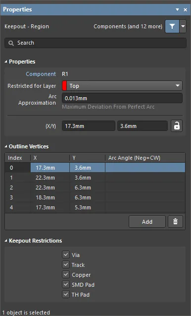
Properties 패널의 Keepout - Region 모드.
속성
-
Component - 이 필드는 선택한 리전 Keepout이 PCB 컴포넌트의 구성 부분인 경우에만 PCB 편집기에 표시되며 상위 PCB 컴포넌트의 지정자를 표시합니다. 클릭 가능한 Component 링크를 선택하면 상위 컴포넌트에 대한 속성 패널의 컴포넌트 모드가 열립니다.
-
Restricted for Layer - 드롭다운을 사용하여 리전 Keepout이 위치한 레이어를 선택합니다.
-
Arc Approximation - 완벽한 호로부터의 최대 편차를 입력합니다.
-
Area - 배치된 개체의 전체 면적을 입력합니다.
-
Locked (Properties 패널에만 해당) - 영역 Keepout을 잠그려면 활성화합니다.
Outline 정점
이 영역은 현재 선택된 영역 개체의 개별 정점을 수정하는 데 사용됩니다. 필요에 따라 기존 정점의 위치를 수정하거나 새 정점을 추가하거나 제거할 수 있습니다. 정점 포인트 간의 호 연결을 정의할 수 있으며, 정점 정보를 CSV 형식의 파일로 내보내고 가져오는 기능도 지원합니다.
-
Vertices Grid - 현재 영역에 대해 정의된 모든 버텍스 포인트를 나열합니다:
-
Index - 버텍스의 할당된 인덱스(편집 불가).
-
X - 버텍스의 X(가로) 좌표. 클릭하여 편집합니다.
-
Y - 버텍스의 Y(세로) 좌표입니다. 클릭하여 편집합니다.
-
Arc Angle (Neg = CW) - 이 꼭지점과 다음 꼭지점을 연결하기 위해 그려지는 호의 각도입니다. 기본적으로 연결은 직선 가장자리이며 이 필드는 비워 둡니다. 클릭하여 편집한 다음 필요에 따라 호 각도를 입력합니다. 양수 값을 입력하면 호가 시계 반대 방향으로 그려집니다. 시계 방향으로 호를 그리려면 음수 값을 입력합니다.
직선 가장자리는 한 꼭지점과 다음 꼭지점을 연결하는 데 사용됩니다. 호로 연결하려면 필요한 Arc Angle 에 값을 입력합니다. 소스 버텍스 포인트와 연결된 필드에 입력하며, 호는 이 버텍스에서 목록의 아래 버텍스까지 연결됩니다.
-
Add - 를 클릭하여 새 버텍스 포인트를 추가합니다. 새 버텍스는 현재 초점이 맞춰진 버텍스 항목 아래에 추가되며 처음에는 초점이 맞춰진 항목과 동일한 X,Y 좌표를 갖습니다.
 을 클릭하여 현재 선택된 버텍스를 제거합니다.
Keepout 제한
이 영역을 사용하여 Keepout으로 제한할 Object 유형을 선택합니다. 객체 유형을 선택 해제하면 해당 클리어런스 규칙을 적용하지 않음으로써 해당 객체 유형의 위반을 허용(차단되지 않음)하게 됩니다. 선택할 수 있는 항목은 다음과 같습니다:
-
Via
-
Track
-
Copper
-
SMD Pad
-
TH Pad
Fill Keepout

채우기 유지
채우기 채우기는 모든 레이어에 배치할 수 있는 원시적인 디자인 개체입니다. 컴포넌트 Outline 정의와 같은 디자인 작업에 사용되는 표준 채우기뿐만 아니라 채우기 채우기라고 하는 두 번째 유형의 채우기도 사용할 수 있습니다. 채우기 채우기는 레이어별 채우기 개체 또는 전체 레이어 채우기 개체로 배치하여 배치 또는 라우팅 장벽과 같은 역할을 할 수 있습니다. 표준 채우기와 Keepout 채우기의 차이점은 거버 또는 ODB++와 같은 레이어별 Keepout 유형 채우기는 출력 생성에 포함되지 않는다는 것입니다. Keepout 채우기는 Keepout 색상의 Outline으로 식별할 수 있습니다.
채우기 Keepout은 신호 레이어 또는 Keepout 레이어에만 배치할 수 있습니다.
채우기 채우기 배치 명령을 실행하면 커서가 십자선으로 바뀌고 채우기 채우기 배치 모드로 들어갑니다. 다음과 같은 일련의 작업을 수행하여 배치합니다:
-
Enter 을 클릭하거나 눌러 채우기 칸의 첫 번째 모서리를 고정합니다.
-
커서를 이동하여 채우기 칸의 크기를 조정한 다음 Enter 을 클릭하거나 눌러 대각선 반대쪽 모서리를 고정하고 채우기 칸 배치를 완료합니다.
-
채우기 칸을 계속 배치하거나 마우스 오른쪽 버튼을 클릭하거나 Esc 을 눌러 배치 모드를 종료합니다.
그래픽 편집 방법을 사용하면 디자인 공간에서 배치된 개체를 직접 선택하고 크기, 모양 또는 위치를 그래픽으로 변경할 수 있습니다.
채우기 채우기 개체를 선택하면 다음과 같은 편집 핸들을 사용할 수 있습니다:
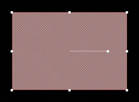
선택된 채우기 채우기
-
모서리 핸들을 클릭한 채로 길게 끌면 세로 및 가로 방향으로 채우기 여백의 크기를 동시에 조정할 수 있습니다.
-
측면, 위쪽 및 아래쪽 핸들을 클릭하고 길게 끌어 세로 및 가로 방향으로 채우기 여백의 크기를 개별적으로 조정합니다.
-
가운데 핸들을 클릭한 채로 길게 끌면 채우기 칸을 중심점을 중심으로 회전합니다.
-
편집 핸들에서 떨어진 채우기 키아웃의 아무 곳이나 클릭한 다음 길게 끌어서 위치를 변경합니다. 드래그하는 동안 채우기 칸을 회전하거나 미러링할 수 있습니다:
-
채우기 칸을 시계 반대 방향으로 회전하려면 Spacebar 을, 시계 방향으로 회전하려면 Shift+Spacebar 을 누릅니다. 회전은 Preferences 대화 상자의 PCB 편집기 - 일반 페이지에 정의된 Rotation Step 값에 따릅니다.
-
X 또는 Y 키를 눌러 X축 또는 Y축을 따라 채우기 Keepout을 미러링합니다.
Fill Keepout Properties

Properties 패널의 Keepout - Fill 모드입니다.
위치
-
(X/Y)
-
X (첫 번째 필드) - 현재 디자인 공간 원점을 기준으로 한 채우기 간격 유지 기준점의 현재 X(수평) 좌표입니다. 채우기 간격의 X 위치를 변경하려면 편집을 클릭합니다. 값은 미터법 또는 영국식으로 입력할 수 있으며, 현재 기본 단위가 아닌 값을 입력할 때는 단위를 포함해야 합니다.
-
Y (두 번째 필드) - 현재 원점을 기준으로 한 채우기 채우기 기준점의 현재 Y(세로) 좌표입니다. 채우기 간격의 Y 위치를 변경하려면 편집합니다. 값은 미터법 또는 영국식으로 입력할 수 있으며, 현재 기본값이 아닌 단위를 입력할 때는 단위를 포함해야 합니다.
-
Rotation - 0( 3 o'clock 수평)에서 시계 반대 방향으로 측정한 채우기 Keepout의 회전 각도(도)를 입력합니다. 채우기 간격의 회전을 변경하려면 편집을 클릭합니다. 최소 각도 분해능은 0.001°입니다.
속성
-
Component - 이 필드는 선택한 채우기 Keepout이 PCB 컴포넌트의 구성 부분인 경우에만 PCB 편집기에 표시되며 상위 PCB 컴포넌트의 지정자를 표시합니다. 클릭 가능한 Component 링크를 선택하면 상위 컴포넌트에 대한 속성 패널의 컴포넌트 모드가 열립니다.
-
Restricted for Layer - 드롭다운을 사용하여 제한된 레이어를 선택합니다.
-
Area - 배치된 개체의 면적을 제공합니다.
-
Length - 채우기 간격의 현재 길이를 표시합니다. 이 필드를 편집하여 0.001밀리에서 10000밀리 범위 내에서 길이를 변경합니다.
-
Width - 채우기 간격의 현재 너비를 표시합니다. 이 필드를 편집하여 0.001밀리~ 10000밀리 범위 내에서 너비를 변경합니다.
값은 mm 또는 mil 단위로 정의할 수 있습니다. 현재 단위가 아닌 다른 단위로 값을 입력할 때는 값에 mm 또는 mil 접미사를 추가합니다.
Keepout 제한
이 영역을 사용하여 Keepout으로 제한할 개체 유형을 선택합니다. 개체 유형을 선택 해제하면 해당 클리어런스 규칙을 적용하지 않음으로써 해당 개체 유형의 위반을 허용(차단되지 않음)하게 됩니다. 선택할 수 있는 항목은 다음과 같습니다:
-
Via
-
Track
-
Copper
-
SMD Pad
-
TH Pad
Keepout 배치
Keepout은 Place » Keepout 메뉴의 편집기 디자인 공간에 배치되며, 지정된 Keepout 스타일(트랙, 채우기, 영역 또는 호)이 현재 활성 레이어에 배치됩니다. Keepout의 속성을 선택하여 물리적 특성, 레이어 또는 개체 유형 제한을 편집할 수 있습니다. 관련 Keepout 속성은 다음과 같습니다:
-
Restricted for Layer - Keepout 레이어, 즉 구리 Object가 제한(Keepout)될 보드 레이어를 설정합니다. 전체 레이어 Keepout의 경우 Keep-Out Layer.
-
Keepout Restrictions - 는 Keepout에 의해 제한될 Object 유형을 결정합니다. Object 유형을 선택 해제하면 해당 클리어런스 규칙을 적용하지 않음으로써 Keepout이 해당 Object 유형의 위반을 허용(Keepout되지 않음)하게 됩니다.
Keepout은 구리 플레인을 제외한 모든 (구리) 신호 레이어에 배치할 수 있습니다. 현재 활성화된 보드 레이어가 Keepout과 호환되지 않는 경우 Place » Keepout 명령을 사용할 수 없습니다(회색으로 표시됨).
아래 이미지에서 두 개의 Keepout 채우기에는 서로 다른 레이어 및 Object 제한이 적용됩니다. 따라서 상단 레이어 Keepout 채우기(왼쪽)는 다른 모든 Object 유형을 제한하면서 스루홀(TH) 패드를 허용하고, Keepout 레이어(오른쪽)는 트랙만 허용할 수 있습니다.
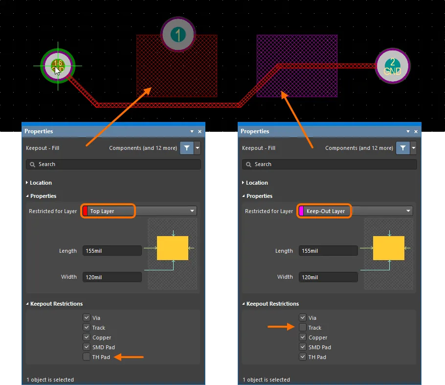
PCB의 서로 다른 레이어에 배치되고 서로 다른 Object 유형의 배치를 제한하도록 구성된 두 개의 Keepout 필의 예시.
Keepout의 고유한 유연성 덕분에 PCB 레이아웃을 제어하기 위한 다양한 작업에 사용할 수 있습니다. Keepout을 오버레이하고, 모든 신호 레이어(예: 상단 또는 하단)에 할당하고, 특정 개체를 거부하도록 구성할 수 있으므로, 예를 들어 비아 스티칭 및 Polygon Pour을 엄격하게 제어하는 데 사용할 수 있습니다.
Polygon Pour 제어
아래 표시된 예제 PCB 레이아웃에서는 잠재적 고전압 영역의 다층 패드 주변에 Keepout Fill이 추가되었으며, 이 영역은 보류 중인 접지 연결 Polygon Pour로부터 충분한 전기적 절연이 필요합니다. Keepout 채우기는 최상위 레이어로 설정되어 구리 Object만 제한하도록 구성되며, 기존 트랙과 패드 등은 허용하면서 Polygon Pour, 채우기 및 영역은 거부합니다. - 즉, 클리어런스 위반 규칙은 '구리'로 분류된 Object에만 적용됩니다.
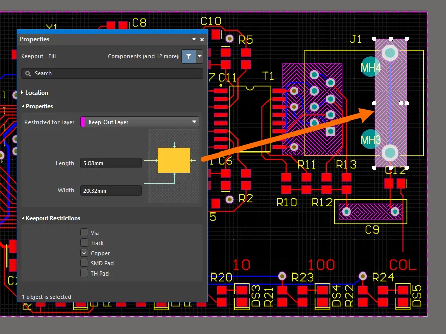
Keepout 채우기는 Keepout 레이어에 배치되고 구리 Object에만 적용되도록 구성됩니다.
위의 Keepout 배열은 신호 레이어(이 경우 상단 및 하단 레이어)에 배치된 폴리곤 푸어가 세 개의 Keepout 영역을 모두 피하도록 강제합니다. 그러나 해당 영역과 관련된 최상위 레이어 pads 는 최상위 레이어 타설에 의해 적절한 간격을 제공받지 못합니다.
이 경우 Polygon Pour이 모든 관련 패드를 적절한 거리만큼 피할 수 있도록 최상위 레이어에 추가 Keepout을 추가할 수 있습니다. 아래 이미지에서는 탑 레이어에 두 개의 Keepout 채우기가 추가되었으며, 명확성을 위해 단일 레이어 모드로 표시되어 있습니다. 표시된 Keepout 범위는 두 개의 겹치는 채우기가 아닌 단일 영역에서 생성되었을 수 있습니다.
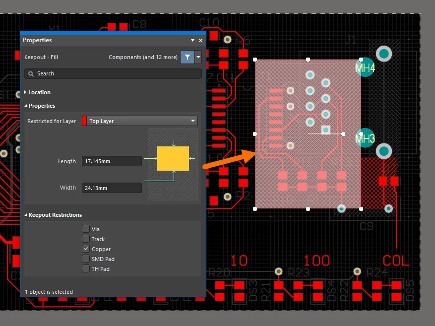
Keepout 채우기는 최상위 레이어에 배치되고 구리 Object에만 적용되도록 구성되었습니다.
폴리곤 채우기가 레이아웃에 최종적으로 추가되면 Keepout 컬렉션이 채우기를 제어하여 영역 주변의 각 레이어에 대해 다른 간격 모양을 생성합니다. 이 예제에서는 사용자 지정 간격 유지 규칙 (아래 참조)으로 인해 간격 유지와 관련된 간격이 일반 Object의 간격보다 큽니다.
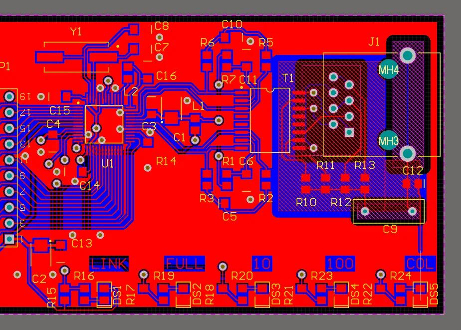
Polygon Pour은 Keepout Object가 배치되지 않도록 합니다.
아래 그림과 같이 단일 레이어 3D 모드에서 레이아웃을 볼 때 왼쪽의 상단 레이어와 오른쪽의 하단 레이어에서 Polygon Pour에 대한 Keepout 컬렉션의 영향을 명확하게 볼 수 있습니다.

단일 레이어 3D 모드에서 표시된 PCB의 상단 레이어(왼쪽) 및 하단 레이어(오른쪽).
여기서는 레이어별 Keepout을 배치하고 구성하기 위한 예제로 Polygon Pour 영역을 제어하는 방법을 사용했습니다. 실제로 폴리곤 타출이 차지하는 영역은
폴리곤 타출 컷아웃을 사용하여 제어하는 것이 가장 좋습니다.
스티칭 제어를 통해
비아 개체를 제한하도록 구성된 Keepout 셰이프를 다층 구리 영역에 적용하면 자동화된 비아 스티칭의 범위를 제어할 수 있습니다(Tools » Via Stitching/Shielding). 모든 레이어 또는 구리 영역 레이어 중 하나에 대해 Keepout 모양을 설정하여 해당 레이어 사이의 비아를 '차단'(제한)할 수 있습니다.
아래 예시에서는 레이아웃의 왼쪽 상단과 하단 모서리에 Keepout 모양이 추가되었습니다. 이는 비아 개체를 제한하도록 구성되어 자동화된 비아 스티칭이 해당 경계 내에 비아를 배치하지 못하도록 합니다.
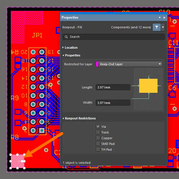
Keepout 영역은 비아에만 적용되도록 구성되었습니다.
비아 스티칭은 일반적으로 기존 트랙, 패드 및 비아를 피하는 것과 함께 해당 클리어런스 규칙에 따라 결정되는 Keepout 모양도 피합니다.
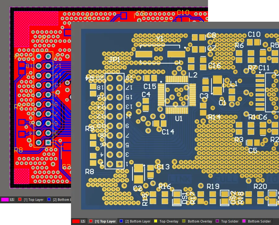
비아 스티칭을 추가한 후의 PCB.
컴포넌트 내 Keepout
Keepout은 PCB 라이브러리 Editor의 컴포넌트 풋프린트에 PCB Editor 디자인 공간에 적용된 것과 동일한 접근 방식을 사용하여 추가됩니다.
아래 표시된 컴포넌트 풋프린트에 추가된 Keepout은 모든 Object를 제한하지만 트랙은 허용하도록 구성되므로 컴포넌트가 사용되는 레이아웃에서 그물 연결을 활성화하는 동시에 다른 Object 유형의 근접 배치를 제한할 수 있습니다.
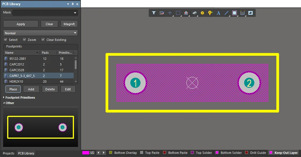
Keepout Object는 PCB 라이브러리 Editor에서 컴포넌트 풋프린트에 추가할 수도 있습니다.
PCB 라이브러리 편집기에서는 디자인 규칙이 적용되지 않으므로 이 경우 Keepout은 해당 범위 내에 있는 스루홀 패드를 허용합니다.
Keepout 작업
Altium Designer의 객체별 Keepout 구현은 모든 관련 기능에 반영되며, 쿼리(따라서 디자인 규칙), PCB 목록 패널 및 가져온/이전 PCB 디자인 문서와의 호환성을 포함합니다.
Keepout 간격 규칙
다른 Object 프리미티브의 경우와 마찬가지로, 현재 전기적 간격 규칙은 Keepout에 대한 간격 제약 조건을 결정합니다( Design » Rules 참조). Keepout에 다른 간격 제약 조건이 필요한 경우 IsKeepOut 속성 검사를 사용자 지정 쿼리로 적용하여 특정 규칙을 생성하세요.
사용자 지정 Keepout 클리어런스 규칙이 기존(전역) 클리어런스 규칙보다 우선순위가 높은 것으로 설정되어 있는지 확인하세요. 아래 예에서는 기본 클리어런스 규칙(Clearance)의 클리어런스 제약 거리가 두 배인 Keepout(Clearance_Keepout)에 대한 규칙을 만들었습니다. 보드 레이아웃 섹션에서 볼 수 있듯이 두 패드 사이에 라우팅된 트랙은 상단 레이어 영역(왼쪽)보다 Keepout 영역(오른쪽)을 더 큰 간격으로 피합니다.
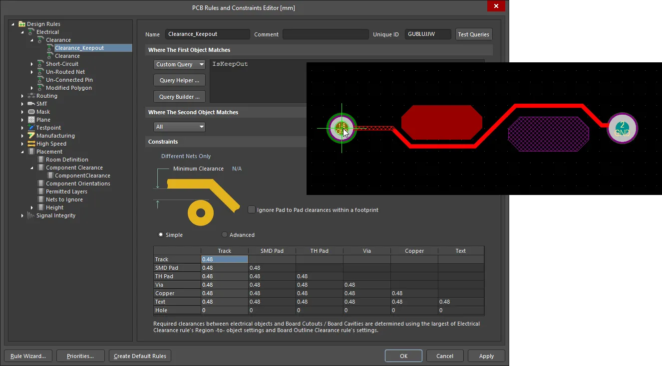
Keepout 객체에 대한 추가 클리어런스 규칙을 만들 수 있습니다.
프리미티브 Object를 Keepout으로 변환
신호 레이어에 있는 기존 프리미티브 Object를 동일한 레이어에서 프리미티브를 Keepout으로 변환 명령(Tools » Convert » Convert Selected Primitives to Keepout)을 사용하여 Keepout으로 변환할 수 있습니다.
Keepout Object는 Tools » Convert » Convert Selected Keepouts to Primitives 명령을 사용하여 동등한 비Keepout 프리미티브 Object로 다시 변환할 수 있습니다.

프리미티브 객체를 동등한 Keepout 객체로 변환할 수 있으며, 그 반대의 경우도 마찬가지입니다.
패널을 통한 액세스
보드 디자인에서 Object별 Keepout은 PCB 목록 및 PCB 필터 패널을 통해 액세스할 수 있습니다.
PCB Filter 패널에서는 IsKeepOut 쿼리 키워드를 사용하여 디자인에서 Keepout 개체를 찾고 (선택 사항으로) 선택할 수 있습니다.

PCB Filter 패널은 디자인에서 Keepout 개체를 찾는 데 사용할 수 있습니다.
PCB List 패널은 아래 목록 패널 이미지에 표시된 것처럼 선택한 유형의 Keepout 객체(예: Keepout 채우기)를 나열, 선택 및 편집하는 데 사용할 수 있습니다. 비교를 위해 표준 최상위 레이어 채우기(마지막에 나열된)도 표시됩니다. all 디자인에 포함된 채우기(또는 영역과 같은 다른 유형의 개체)가 Keepout으로 할당된 경우 PCB List 패널에 전체 Keepout 개체 제한 속성이 포함됩니다.

PCB List 패널을 사용하여 선택한 유형의 Keepout 개체를 나열, 선택 및 편집할 수 있습니다.
PCB List 패널에 나열된 Keepout 속성은 이 경우 채우기가 Keepout 개체로 지정되어 있으므로 읽기 전용입니다. 마찬가지로 PCB List 패널에 있는 Keepout 개체의 Net 속성은 정의상 Keepout 개체를 넷에 할당할 수 없으므로 편집할 수 없습니다.
PCB 디자인 가져오기
Altium Designer는 가져오기 마법사 (File » Import Wizard)에서 제공하는 자동 변환 기능을 사용하여 다양한 다른 디자인 도구에서 디자인 파일을 가져올 수 있습니다. 다른 디자인 도구의 PCB 디자인 파일에 포함된 Keepout 유형 Object(일부 Object별)는 가능한 경우 마법사를 통해 Object별 Keepout으로 변환됩니다.
마법사의 Keepout 변환 프로세스는 멘토® 그래픽 패드™ 및 Cadence® 알레그로™와 같은 인기 있는 ECAD 시스템의 기판 설계와 호환됩니다. 올바른 Keepout 해석은 IDF 내보내기 프로세스 중에도 이루어집니다.