
Измерение расстояний на печатной плате
Проектирование печатной платы — это прежде всего точные размеры и выверенные измерения. Объекты тщательно задаются с точными габаритами и точно размещаются в пределах рабочей области проектирования. Всё в печатной плате требует аккуратной настройки и размещения.


Редактор PCB поддерживает два типа измерений в каждом из режимов редактирования:
-
2D editing mode вы можете: измерять distance between any two points в области редактирования или distance between any two objects.
-
3D editing mode вы можете: измерять distance between any two 3D objects или distance between two recognized reference points on 3D objects.
Измерения в редакторе PCB
Редактор PCB использует Unified Cursor-Snap System для позиционирования курсора в области редактирования. Привязка курсора срабатывает при выполнении измерений, играя ключевую роль в процессе измерения. Поэтому важно понимать, как управлять и настраивать привязку курсора во время редактирования.
В системе привязки курсора есть два основных аспекта: what к чему привязывается курсор и when как он будет привязываться.
-
What - точки в пространстве, к которым привязывается курсор, включают: заданные пользователем Grids, рабочие Guides, и точки привязки на Objects.
-
When - курсор привязывается к точке привязки, когда он находится в пределах Snap Distance, и привязка разрешена на этом Layer.
Демонстрация различных вариантов поведения привязки курсора.
Измерение расстояния между двумя точками в 2D
Чтобы измерить и отобразить расстояние между любыми двумя точками в текущем документе:
Измерение расстояния между двумя точками.
-
Выберите команду Reports » Measure Distance в главном меню (горячая клавиша:
Ctrl+M). При входе в режим измерения курсор меняется на перекрестие. -
В строке состояния появляется подсказка: Select Measure Start Point. Установите курсор в точку, откуда нужно начать измерение, затем щёлкните или нажмите
Enter. -
Переместите курсор в требуемую конечную точку и щёлкните или нажмите
Enterещё раз. При перемещении курсора для удобства отображается измерительная линия. -
Появится диалог Measure Distance (
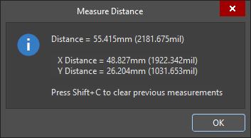 ), в котором отображаются: расстояние «точка-точка», расстояние по X (горизонталь) и расстояние по Y (вертикаль) — как в метрических (мм), так и в дюймовых (mil) единицах. Чтобы скопировать содержимое диалога в буфер обмена Windows, нажмите
 Ctrl+C. -
Измерение также визуально отображается в рабочей области, показывая расстояния X, Y и прямое расстояние. Прямое (кратчайшее) расстояние показано жёлтым, а расстояния X и Y — светло-голубым. Чтобы переключать результаты между метрическими и дюймовыми единицами, нажмите горячую клавишу
Q. -
Измерение также отображается на панели Messages. Дважды щёлкните по результату на панели, чтобы вернуться к более раннему измерению, и снова отобразить его измерительные линии в рабочей области. Уровень масштабирования настраивается на странице System – Navigation диалога Preferences (
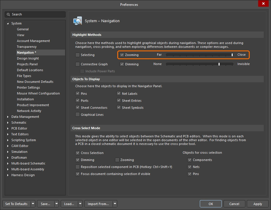 ).
).
-
Продолжайте измерять расстояния между другими точками либо щёлкните правой кнопкой или нажмите
Escдля выхода из режима измерения. -
Чтобы очистить предыдущие измерения из рабочей области, нажмите
Shift+C.
Измерение расстояния между двумя примитивными объектами в 2D
Чтобы измерить и отобразить расстояние между краями любых двух примитивных объектов в текущем документе:
Измерение расстояния между двумя примитивами.
-
Выберите команду Reports » Measure Primitives в главном меню. При входе в режим измерения курсор меняется на перекрестие.
-
В строке состояния появляется подсказка: Choose First Primitive. Установите курсор в любом месте над первым примитивом, затем щёлкните или нажмите
Enter. Чтобы иметь возможность выбрать примитив этой командой, соответствующий тип примитива должен быть включён в фильтре выбора (Selection Filter,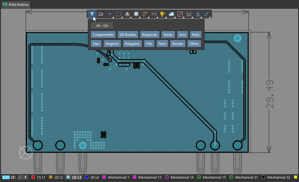 ).
).
-
Переместите курсор в любое место над вторым примитивом, затем щёлкните или нажмите
Enterещё раз. -
Появится диалог Clearance (
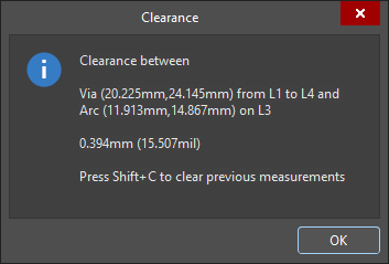 ), в котором отображается минимальный зазор между двумя выбранными примитивами — он может находиться не в той точке, где вы щёлкнули. Диалог также содержит информацию о слое и расположении каждого из примитивов. Чтобы скопировать содержимое диалога Clearance в буфер обмена Windows, нажмите
 Ctrl+C. -
Измерение также визуально отображается в рабочей области, показывая расстояния X, Y и прямое расстояние. Прямое (кратчайшее) расстояние показано жёлтым, а расстояния X и Y — светло-голубым. Чтобы переключать результаты между метрическими и дюймовыми единицами, нажмите горячую клавишу
Q. -
Измерение также отображается на панели Messages. Дважды щёлкните по результату предыдущего измерения на панели Messages , чтобы выполнить кросс-переход к этому измерению и снова отобразить его измерительные линии в рабочей области. Уровень масштабирования настраивается на странице System – Navigation диалога Preferences (
).
-
Продолжайте измерять расстояния между другими примитивами либо щёлкните правой кнопкой или нажмите
Escдля выхода из режима измерения. -
Чтобы очистить предыдущие измерения из рабочей области, нажмите
Shift+C.

Измерение длины выбранных объектов
Чтобы измерить длину выбранных дорожек и дуг в текущем проекте:
Измерение длины выбранных дорожек и дуг.
-
Выберите дорожки и дуги, длину которых нужно измерить.
-
Выберите команду Reports » Measure Selected Objects в главном меню. Обратите внимание: выбранные заливки, регионы, площадки или переходные отверстия не включаются в измерение.
-
Появится диалог Information (
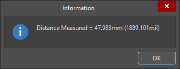 ), в котором приводится суммарная измеренная длина выбранных дорожек и дуг. Чтобы скопировать содержимое диалога Information в буфер обмена Windows, нажмите
 Ctrl+C. -
Измерение также отображается на панели Messages.
Измерение расстояния между 3D-объектами или гранями
Чтобы измерять расстояния между 3D-объектами:
Выполняйте точные измерения «объект-объект» в режиме 3D Layout Mode. Кратчайшее расстояние между выбранными объектами показано жёлтым.
-
Выберите команду Reports » Measure 3D Objects в главном меню. При входе в режим измерения курсор меняется на перекрестие.
-
Выберите первый 3D-объект или конкретную грань этого объекта. При наведении курсора на потенциальный 3D-объект его цвет меняется на зелёный. Чтобы выбрать конкретную грань объекта, удерживайте клавишу
Ctrlпри перемещении курсора — грань, находящаяся под курсором, будет подсвечена. Когда нужный объект/грань подсвечены, щёлкните или нажмитеEnterдля подтверждения выбора. -
До выбора второго объекта инструмент будет показывать измерения кратчайшего расстояния от нижней стороны этого первого объекта (грани) до поверхности платы, а также кратчайшего расстояния от этого первого объекта (грани) до края платы.
-
Наведите курсор так, чтобы подсветить второй 3D-объект/грань, и щёлкните или нажмите
Enterдля подтверждения выбора. -
Появляется диалог 3D Distance (
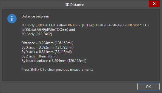 ), в котором сообщается: какие два 3D-объекта были выбраны, кратчайшее расстояние «точка‑точка» между объектами (в самой низкой возможной точке по плоскости Z), расстояние по плоскости X (горизонтальное) и расстояние по плоскости Y (вертикальное) — как в метрических (мм), так и в имперских (mil) единицах. Чтобы скопировать содержимое диалога в буфер обмена Windows, нажмите
 Ctrl+C. -
Измерения также отображаются визуально в рабочем пространстве, показывая расстояния по плоскости X, по плоскости Y и прямое расстояние. Прямое (кратчайшее) расстояние показано жёлтым цветом, а расстояния по X и Y — светло‑голубым. Чтобы переключать результаты между метрическими и имперскими единицами, нажмите сочетание клавиш
Q. -
Измерение также отображается на панели Messages. Дважды щёлкните по результату на панели, чтобы вернуться к более раннему измерению, и снова отобразить его измерительные линии в рабочем пространстве. Уровень масштабирования настраивается на странице System – Navigation диалога Preferences (
).
-
Продолжайте измерять расстояние между другими объектами/гранями или щёлкните правой кнопкой мыши либо нажмите
Esc, чтобы выйти из режима измерения. -
Чтобы очистить предыдущие измерения из рабочего пространства, нажмите
Shift+C.
Измерение расстояния между точками на 3D Bodies
Чтобы измерить расстояния между двумя точками на одном и том же 3D Body или между точками на двух разных 3D bodies:
Измерьте между 2 точками на 3D-объектах.
-
Переключитесь в режим 3D Layout Mode (сочетание: 3).
-
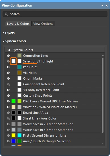
Для этого типа измерений может быть полезно отобразить опорные точки в 3D-моделях, включая 3D Reference Points, заложенные в модели, а также Custom Snap Points, добавленные в редакторе библиотек PCB (
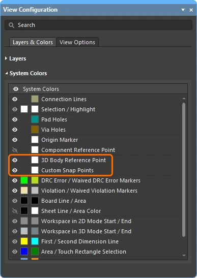 ).
).
-
Выберите команду Tools » 3D Body Placement » Measure Distances в главном меню. При входе в режим измерения курсор меняется на перекрестие.
-
Первый щелчок — чтобы назначить первую 3D-модель: щёлкните в любом месте объекта. По мере перемещения 3D-позиционного курсора (синий, шестиконечный) он будет перескакивать между доступными вершинами, опорными точками и точками привязки в этой модели (
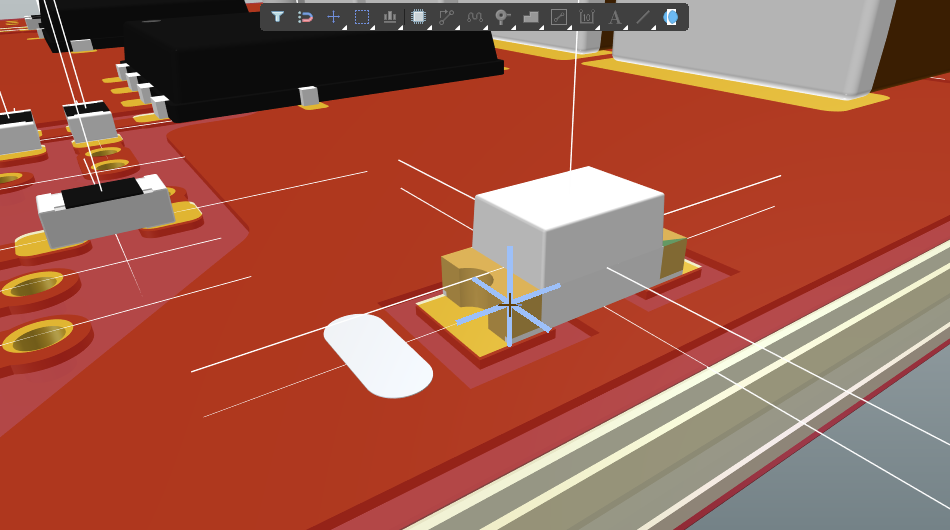 ).
).
-
Расположите 3D-позиционный курсор и щёлкните, чтобы назначить вершину или точку привязки в качестве первой точки измерения на этой 3D-модели.
-
Следующий щелчок может быть одним из двух вариантов:
-
Найти вершину или точку привязки 3D-позиционным курсором на той же 3D-модели, затем щёлкнуть, чтобы назначить её второй точкой измерения.
-
Либо можно переместить маленький курсор‑перекрестие на другую 3D-модель, щёлкнуть один раз, чтобы назначить эту модель, затем расположить 3D-позиционный курсор на вершине или точке привязки на второй модели и щёлкнуть ещё раз, чтобы назначить вторую точку измерения.
-
-
Появляется диалог Information (
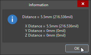 ), в котором показано прямое расстояние «точка‑точка», а также расстояния «точка‑точка» вдоль плоскостей X, Y и Z — как в метрических, так и в имперских единицах.
-
Продолжайте измерять следующие расстояния или щёлкните правой кнопкой мыши либо нажмите Esc, чтобы выйти.
 ).
). Локализовано с помощью ИИ