
Подготовка вашего проекта к производству
Заключительный этап цикла проектирования — сформировать выходные файлы, необходимые для производства изделия. Для этого нужно сгенерировать набор выходных файлов в различных форматах. Как разработчик, вы можете по отдельности настраивать и генерировать выходные данные через редакторы схемы и PCB, либо, как вариант, добавить все требуемые выходные данные в OutputJob и затем генерировать их в рамках процесса выпуска (release) проекта.
 и выполнить сборку печатной платы (PCB).")

Конечная цель — изготовить изделие, например, произвести (fabricate) и выполнить сборку печатной платы (PCB).
Подготовка производственных данных с помощью Output Jobs
Вы можете по отдельности настроить и сгенерировать выходные данные напрямую через меню File и Reports соответствующих редакторов. В этом случае выходные данные генерируются непосредственно при нажатии OK в связанном диалоге настроек и записываются в расположение, указанное в поле Output Path на вкладке Options tab диалога Project Options.
Однако файлы Output Job упрощают подготовку выходных данных для ваших проектов и их последующую генерацию с использованием высоконадежного процесса выпуска проекта. Output Job, или сокращенно «OutJob», по сути представляет собой предварительно настроенный набор выходных данных, который хранит параметры этих выходных данных и определяет, куда будут записаны сгенерированные результаты.
Чтобы добавить новый OutJob в проект, щелкните правой кнопкой мыши по записи проекта на панели Projects и выберите команду Add New to Project » Output Job File в контекстном меню. В рабочей области откроется OutJob по умолчанию.

Вновь созданный OutJob будет активным документом в рабочей области.
С левой стороны OutJob можно добавлять и настраивать многочисленные типы выходных данных для разных задач. Выходные данные сгруппированы по функциональным категориям, таким как Assembly Outputs, Fabrication Outputs и Report Outputs.
Добавьте новый выходной документ нужного типа, щелкнув по соответствующему тексту Add New <Type> Output внизу категории и выбрав требуемый тип в всплывающем меню. Для записи типа выходных данных предусмотрено подменю, в котором можно указать источник данных, то есть какие исходные документы будут использоваться при генерации. Можно добавить любое количество выходных данных.

Для некоторых типов выходных данных доступны параметры настройки добавленного выхода: щелкните правой кнопкой мыши по выходу в списке и выберите команду Configure в контекстном меню. Откроется соответствующий диалог конфигурации для задания параметров. Например, для выхода Gerber X2 Setup откроется диалог Gerber X2 Setup.

Настройте выходные данные в соответствующем диалоге настройки.
Чтобы определить, куда и в каком формате будут генерироваться выходные данные, используются контейнеры выходных данных и задания печати. Выходные данные могут записываться (где применимо) в три типа контейнеров — PDF, видео или структуру папок (конкретный формат выходного файла, например Gerber). Некоторые выходные данные также можно отправлять напрямую на печатающее устройство в виде бумажной копии, добавив и настроив задание печати.
Новый OutJob содержит по одному контейнеру каждого типа и задание печати для принтера по умолчанию. Их записи отображаются справа в OutJob. При необходимости новый контейнер выходных данных или задание печати можно добавить, нажав элемент управления Add New Output Container и выбрав нужный тип контейнера, либо нажав элемент управления Add New Print Job и выбрав нужный принтер соответственно.

Добавьте новые контейнеры выходных данных и/или задания печати по мере необходимости.
Чтобы указать, какие выходные данные должны генерироваться через какой контейнер/задание печати, выберите контейнер/задание и затем установите флажок Enabled для каждого нужного выхода в списке. После включения зеленая линия соединит выходные данные с выбранным контейнером/заданием печати. Выходные данные можно сопоставлять с индивидуальными или общими контейнерами/заданиями печати.

Сопоставьте добавленные выходные данные с соответствующими контейнерами и заданиями печати с помощью флажков Enabled.
Чтобы настроить контейнер выходных данных/задание печати, выберите его запись и нажмите элемент управления Change . Откроется соответствующий диалог — например, при выборе контейнера «структура папок» откроется диалог Folder Structure settings, где можно настроить расположение выходных файлов и дополнительные параметры, связанные с генерацией файлов.

Настройте параметры контейнера выходных данных/задания печати в соответствующем диалоге.
Настроенные в OutJob выходные данные можно генерировать либо непосредственно из OutJob, либо, для проекта PCB, в рамках высоконадежного процесса выпуска проекта. Чтобы сгенерировать выходные данные, связанные с контейнером/заданием печати, прямо из OutJob, выберите контейнер/задание и нажмите элемент управления Generate content или Print соответственно.

Вы можете генерировать или печатать выходные данные напрямую из OutJob.
Выпуск проекта платы (Board Design Release)
Используя процесс выпуска проекта платы, вы можете одновременно сгенерировать все производственные данные, настроенные в файлах OutJob вашего PCB-проекта. Этот процесс имеет ряд преимуществ по сравнению с генерацией выходных данных по отдельности или напрямую из OutJob, включая возможность валидации проекта как неотъемлемой части процесса выпуска и исключение ручного вмешательства в ходе выпуска. Кроме того, при выпуске в подключенное Workspace обеспечивается тесная интеграция с системой контроля версий Workspace.
Чтобы начать выпуск проекта, щелкните правой кнопкой мыши по его записи на панели Projects и выберите команду Project Releaser в контекстном меню. Представление Release откроется в отдельной вкладке.

Откройте представление Release — пользовательский интерфейс для Project Releaser.
Процесс выпуска — это поэтапный поток; записи слева в представлении Release показывают, на каком этапе вы находитесь.
На начальном этапе процесса выпуска вы можете нажать кнопку Options внизу слева, чтобы открыть диалог Project Release Options и настроить параметры процесса выпуска. Параметры включают выбор цели выпуска (Workspace, папка или zip-файл) и назначение OutJob.

Настройте параметры выпуска в диалоге Project Release Options.
В зависимости от выбранной цели выпуска этапы процесса немного различаются. Ниже в качестве примера показан выпуск в подключенное Workspace.
|
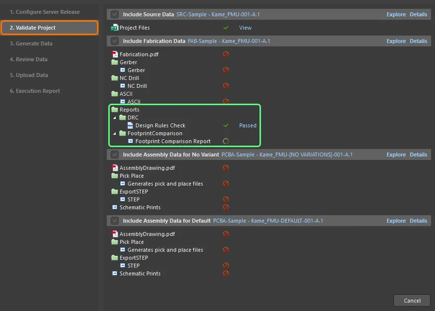
На этапе Configure Server Release вы можете указать тип(ы) данных, которые хотите сгенерировать: исходные данные (снимок исходного проекта, всегда включается в выпуск), данные для изготовления (fabrication) и данные для сборки (assembly). Количество наборов данных для сборки будет соответствовать базовому (без вариантов) проекту и всем обнаруженным вариантам проекта. Когда будете готовы, нажмите кнопку Prepare внизу справа, чтобы продолжить. Если будут обнаружены проблемы, вам предложат решения для их устранения. Этап Validate Project запускается автоматически, когда в назначенных файлах OutJob обнаруживаются один или несколько отчетов типа валидации, например отчет Design Rule Check, и выполняются соответствующие выходные данные валидации. Выпуск завершится неудачей, если какие-либо проверки валидации не будут успешно пройдены. Этап Generate Data запускается автоматически, когда предыдущий этап завершается без проблем. На этом этапе выполняются все остальные выходные данные, определенные в назначенных файлах OutJob, для генерации данных, подлежащих выпуску. После успешного прохождения всех проверок валидации и генерации выходных данных этап Review Data позволяет просмотреть сгенерированные данные. Продолжите выпуск, нажав кнопку Release внизу справа и подтвердив выпуск в появившемся диалоге. После подтверждения выпуска на предыдущем этапе автоматически выполняется переход на этап Upload Data . Он отображает ход загрузки данных. Заключительный этап Execution Report процесса предоставляет сводку по выпуску. После выпуска проекта вы можете закрыть представление Release , нажав кнопку Close внизу справа. |


 Локализовано с помощью ИИ