Объект Text размещает однострочную строку или многострочный текстовый фрейм на выбранном слое в различных стилях и форматах отображения, включая популярные стандарты штрихкодов и QR-коды. Это может быть пользовательский текст или особый тип строки, называемый специальной строкой (special string), которую можно использовать для отображения информации о плате или системе либо значений пользовательских параметров на плате. Текстовый фрейм — это прямоугольная область с изменяемыми размерами, которая может содержать несколько строк текста и может автоматически переносить и обрезать текст, чтобы он оставался в пределах границ фрейма.

Размещённые объекты Text
Объекты Text доступны для размещения как в редакторе PCB, так и в редакторе посадочных мест (PCB footprint) — для этого в главном меню выберите команду Place » String или Place » Text Frame . После запуска команды размещения строки курсор изменится на перекрестие, и вы перейдёте в режим размещения текста. Объект Text появится «плавающим» на курсоре:
-
Установите курсор, затем щёлкните или нажмите Enter, чтобы разместить объект Text.
-
Продолжайте размещать следующие объекты Text либо щёлкните правой кнопкой мыши или нажмите Esc, чтобы выйти из режима размещения.
В зависимости от выбранной команды размещения (
Place » String или
Place » Text Frame), размещаемый объект Text будет в режиме
String или
Frame, который можно изменить на панели
Properties panel во время или после размещения.
Дополнительные действия, которые можно выполнять во время размещения:
-
Нажмите Spacebar, чтобы повернуть объект Text против часовой стрелки, или Shift+Spacebar — по часовой стрелке. Поворот выполняется в соответствии со значением Rotation Step , заданным на странице PCB Editor – General page диалога Preferences.
-
Нажмите клавиши X или Y, чтобы отзеркалить объект Text по оси X или по оси Y.
-
Нажмите клавишу L, чтобы перевернуть объект Text на другую сторону платы.
-
Нажмите клавиши + и - (на цифровой клавиатуре), чтобы циклически переходить вперёд и назад по всем видимым слоям в проекте и быстро менять слой размещения.
Графический способ редактирования позволяет выбрать размещённый объект Text непосредственно в рабочей области и изменить его положение, поворот, ориентацию и размер.
Когда объект Text выбран, доступны следующие маркеры редактирования:

Выбранный Text
-
Щёлкните и перетащите B, чтобы повернуть объект Text вокруг его опорной точки A (обозначена маленьким x).
-
Щёлкните и перетащите C, чтобы изменить размер ограничивающей рамки объекта Text одновременно по вертикали и горизонтали.
-
Щёлкните и перетащите D, чтобы изменить размер ограничивающей рамки объекта Text по вертикали и горизонтали раздельно.
-
Щёлкните в любом месте объекта Text вдали от маркеров редактирования и перетащите, чтобы переместить его. Во время перетаскивания комментарий можно поворачивать или зеркалить:
-
Нажмите Spacebar, чтобы повернуть объект Text против часовой стрелки, или Shift+Spacebar — по часовой стрелке. Поворот выполняется в соответствии со значением Rotation Step , заданным на странице PCB Editor – General page диалога Preferences.
-
Нажмите клавиши X или Y, чтобы отзеркалить объект Text по оси X или по оси Y.
-
Текст по умолчанию для вновь размещаемого строкового объекта — String. После размещения (если он не был изменён до или во время размещения) измените этот текст при необходимости, используя окно ввода текста при просмотре свойств строки через панель Properties .
-
Программное обеспечение позволяет размещать объекты Text в виде символов штрихкода непосредственно на PCB на любом слое, что упрощает нанесение штрихкодов на плату в рамках производственного процесса. Подробнее об использовании объекта Text в качестве штрихкода см. раздел Adding a Barcode на странице Including Barcodes & Logos.
-
Программное обеспечение позволяет размещать объекты Text в виде QR-кодов непосредственно на PCB на любом слое, что позволяет легко печатать QR-коды на плате в рамках производственного процесса. Подробнее об использовании объекта Text в качестве QR-кода см. раздел Adding a QR Code на странице Including Barcodes & Logos.
Специальные строки
Хотя объекты Text можно использовать для размещения пользовательского текста на текущем слое PCB, размещать можно не только only пользовательский текст. Для упрощения подготовки документации используется концепция special strings. Они работают как заполнители (placeholders) для информации о проекте, системе или проекте в целом, которая должна отображаться на PCB в момент генерации выходных данных.
 и преобразованные (второе изображение).")
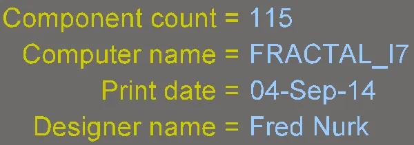
Примеры специальных строк проектирования, системы и параметров проекта, показанные как исходные строки (первое изображение) и преобразованные (второе изображение).
Специальные строки, доступные в документе PCB, поступают из нескольких источников:
-
Для новых документов PCB предоставляется набор предопределённых специальных строк по умолчанию.
-
Пользовательские специальные строки можно добавить, определив дополнительные параметры на уровне проекта (эти параметры задаются на вкладке Parameters tab диалога Project Options) и на уровне варианта (эти параметры задаются в диалоге Edit Project Variant dialog или на панели Properties panel в режиме Variant в Variant Manager).
-
Пользовательские параметры, добавленные к компонентам в области схемы, передаются через ECO и становятся доступными для компонентов PCB. Если специальная строка, ссылающаяся на параметр компонента, добавлена к посадочному месту PCB на уровне исходной библиотеки, эта строка будет интерпретирована на целевом механическом слое или оверлее при размещении компонента PCB.
Примечания по использованию специальных строк
-
Специальная строка обозначается тем, что строка начинается с символа . (точка) (например,
.Layer_Name, .Net_Count и т. д.). Если строка начинается с ".", вся строка рассматривается как «специальная». Этот синтаксис также используется при обращении к пользовательскому параметру: имя параметра предваряется символом "." (точка).
-
Чтобы включить более одной специальной строки в текст PCB, заключайте каждую специальную строку в апострофы ( ' ); например:
'.Pcb_File_Name_No_Path' '.Print_Date'.
-
Также можно использовать текст, пробелы и специальные символы между конкатенированными специальными строками, например:
FileName= '.Pcb_File_Name_No_Path' : PrintDate = '.Print_Date'.
-
Пробелы и специальные символы также могут использоваться в именах параметров Project и Variant.
-
Значения некоторых специальных строк можно увидеть только при генерации соответствующего вывода, включая .Legend, .Plot_File_Name и .Printout_Name. Большинство специальных строк можно просматривать на экране.
При формировании документации для проекта PCB и выпуске в Workspace должен быть способ указать, к какому Item и Revision относится документация, а также конфигурацию проекта, использованную при выпуске, и применимый управляющий вариант (driving variant), если он есть. Для этого доступен набор специальных строк, включая .PCBConfigurationName, .ItemAndRevision и .VariantName. Эти специальные строки не интерпретируются до момента генерации выходных данных (если только вы не просматриваете PCB в 3D, что само по себе считается выводом). Информацию, предоставляемую этими строками, можно увидеть в сгенерированных выходных данных, включая файлы Gerber/ODB++, распечатки Final Artwork, распечатки PCB, 3D-распечатки PCB, PCB 3D Video и сборочные чертежи.
-
Специальные строки автоматически преобразуются для отображения на экране. Если строку невозможно преобразовать, будет показано либо значение введённой строки, либо сообщение. Например, если проект не находится под контролем версий и на PCB размещена специальная строка
.VersionControl_RevNumber, будет отображено сообщение Not in Version Control.
-
Чтобы упростить идентификацию специальных строк, на панели View Configuration panel есть параметр Special Strings . Когда он включён, любые размещённые текстовые объекты, сформированные из преобразованных специальных строк, будут накладываться (маркироваться) именем исходной (непреобразованной) специальной строки.

Размещение специальной строки
Чтобы использовать специальную строку на PCB, разместите объект Text, затем выберите одно из имён специальных строк из выпадающего списка поля Text (режим String) или из выпадающего списка  (режим Frame) на панели Properties.

Доступ к специальным строкам для размещённого строкового объекта.
Ниже приведены предопределённые системные специальные строки, доступные для использования в документе PCB:
-
.Application_BuildNumber – версия программного обеспечения, в котором PCB в данный момент загружена. При генерации Gerber-вывода используйте эту строку, чтобы зафиксировать сборку ПО, в которой был создан проект.
-
.Arc_Count – количество дуг на PCB.
-
.BlindVia_Count – количество глухих переходных отверстий (blind vias) на PCB.
-
.Board_Height – вертикальный размер платы PCB.
-
.Board_Width – горизонтальный размер платы PCB.
-
.BuriedVia_Count – количество скрытых переходных отверстий (buried vias) на PCB.
-
.Comment – строка комментария для компонента (размещается на любом слое в редакторе библиотек как часть посадочного места компонента).
-
.Component_Count – количество компонентов на PCB.
-
.ComponentMixed_Count – количество компонентов со смешанными площадками на PCB.
-
.ComponentSMD_Count – количество компонентов с SMD-площадками на PCB.
-
.ComponentThru_Count – количество компонентов с выводными (thru-hole) площадками на PCB.
-
.ComputerName– имя компьютера, на котором установлено и запущено ПО.
-
.CopperInner_Weight_Max – максимальная толщина меди на внутренних слоях.
-
.CopperOuter_Weight_Max – максимальная толщина меди на внешних слоях.
-
.Designator – строка позиционного обозначения компонента (размещается на любом слое в редакторе библиотек как часть посадочного места компонента).
-
.Fill_Count – количество заливок на печатной плате.
-
.Hole_Count – количество сверловочных отверстий на печатной плате.
-
.Hole_Size_Min – минимальный диаметр отверстия на печатной плате.
-
.Hole_Size_Num – количество уникальных диаметров отверстий на печатной плате.
-
.Item – элемент (Item), к которому относятся сгенерированные данные (например, D-810-2000). Эти данные будут использованы для изготовления этого элемента.
-
.ItemAndRevision – элемент (Item) и конкретная ревизия этого элемента, к которым относятся сгенерированные данные, в формате <Item ID>-<Revision ID> (например, D-810-2000-01.A.1). Эти данные будут использованы для изготовления именно этой ревизии данного элемента.
-
.ItemRevision – конкретная ревизия элемента (Item), к которой относятся сгенерированные данные (например, 01.A.1). Данные сохраняются в этой ревизии элемента (Item Revision) на целевом сервере.
-
.ItemRevisionBase – часть Base Level в схеме именования ревизии элемента (Item Revision) (например, 1).
-
.ItemRevisionLevel1 – часть Level 1 в схеме именования ревизии элемента (Item Revision) (например, A).
-
.ItemRevisionLevel1AndBase – части Level 1 и Base Level в схеме именования ревизии элемента (Item Revision) (например, A.1).
-
.ItemRevisionLevel2 – часть Level 2 в схеме именования ревизии элемента (Item Revision) (например, 01).
-
.ItemRevisionLevel2AndLevel1 – части Level 2 и Level 1 в схеме именования ревизии элемента (Item Revision) (например, 01.A).
-
.Layer_Count – количество медных слоев на печатной плате.
-
.Layer_Name – имя слоя, на котором размещена строка.
-
.Legend – легенда символов для механических сверловочных чертежей. Эта строка действительна только при размещении на слое Drill Drawing. Примечание: это устаревшая функция; для более подробной информации о сверловке размещайте объект Drill Table.
-
.MicroVia_Count – количество микровий на печатной плате.
-
.ModifiedDate – отметка даты изменения печатной платы; заполняется автоматически. Пример: 23/09/2015.
-
.ModifiedTime – отметка времени изменения печатной платы; заполняется автоматически.
-
.Net_Count – общее количество различных цепей (nets) на печатной плате.
-
.Net_Names_On_Layer – имена всех цепей на указанном слое. Эта строка действительна только при размещении на внутреннем слое плоскости (internal plane).
-
.Pad_Count – количество площадок (pads) на печатной плате.
-
.PadSMD_Count – количество SMD-площадок на печатной плате.
-
.PadThru_Count – количество выводных (thru-hole) площадок на печатной плате.
-
.Pattern – имена посадочных мест (footprints) компонентов, используемых на печатной плате.
-
.Pcb_File_Name – путь и имя файла документа печатной платы.
-
.Pcb_File_Name_No_Path – имя файла документа печатной платы.
-
.PCBConfigurationName – отображает имя набора данных, из которого был сгенерирован вывод, как определено в Project Releaser. Обратите внимание, что имена конфигураций по умолчанию Source, Fabrication и Assembly нельзя редактировать (например, вывод Fabrication будет отображать Fabrication для .PCBConfigurationName). Пользовательские конфигурации Custom будут отображать заданное пользователем имя при использовании этой специальной строки (показать изображение![]() ).
).
-
.Plot_File_Name – для сгенерированного вывода Gerber эта строка определяет имя файла Gerber-слоя. Для печатного вывода она определяет слой, показанный в выводе. Для вывода ODB++ она определяет имя родительской папки, в которой хранятся файлы.
-
.Poly_Count – количество полигонов на печатной плате (включая polygon pours, internal planes и split planes).
-
.Print_Date – дата печати/построения (plotting).
-
.Print_Scale – коэффициент масштаба печати/построения.
-
.Print_Time – время печати/построения.
-
.Printout_Name – имя распечатки.
-
.SlotHole_Count – количество продолговатых (slotted) отверстий на печатной плате.
-
.SolderMask_Bottom – наличие нижней паяльной маски. Если слоя нижней паяльной маски нет, параметр будет иметь значение No mask. Если слой нижней паяльной маски есть, но его цвет не задан, параметр будет иметь значение No color . Если слой нижней паяльной маски есть и его цвет задан, параметр покажет цвет — либо его имя (Green, Black, Blue, Red и т. д.), либо его RGBA-код (например, #FF0065FF).
-
.SolderMask_Top – наличие верхней паяльной маски. Если слоя верхней паяльной маски нет, параметр будет иметь значение No mask. Если слой верхней паяльной маски есть, но его цвет не задан, параметр будет иметь значение No color . Если слой верхней паяльной маски есть и его цвет задан, параметр покажет цвет — либо его имя (Green, Black, Blue, Red и т. д.), либо его RGBA-код (например, #FF0065FF).
-
.SquareHole_Count – количество квадратных отверстий на печатной плате.
-
.StackedVia_Count – количество «стековых» переходных отверстий (stacked vias) на печатной плате.
-
.String_Count – количество строк (strings) на печатной плате.
-
.Thru_Via_Count – количество сквозных переходных отверстий (thru-hole vias) на печатной плате.
-
.Total_Thickness – толщина платы.
-
.Total_Thickness(Board Layer Stack) – толщина стека слоев платы.
-
.Track_Count – количество дорожек на печатной плате.
-
.VariantName – вариант проекта, из которого был создан вывод.
-
.VersionControl_PrjFolderRevNumber – текущий номер ревизии проекта, который увеличивается при каждом полном коммите проекта (т. е. включая файл проекта). Для того чтобы эта строка содержала какую-либо информацию, необходимо использовать систему контроля версий.
-
.VersionControl_ProjFolderRevNumber – текущий номер ревизии проекта, который увеличивается при каждом полном коммите проекта (т. е. включая файл проекта). Для того чтобы эта строка содержала какую-либо информацию, необходимо использовать систему контроля версий.
-
.VersionControl_ProjFolderRevNumberShort – короткий формат Git-хэша (первые восемь символов) проекта. Для того чтобы эта строка содержала какую-либо информацию, необходимо использовать систему контроля версий.
-
.VersionControl_RevNumber – текущий номер ревизии документа. Для того чтобы эта строка содержала какую-либо информацию, необходимо использовать систему контроля версий.
-
.VersionControl_RevNumberShort – короткий формат Git-хэша (первые восемь символов) текущего номера ревизии документа. Для того чтобы эта строка содержала какую-либо информацию, необходимо использовать систему контроля версий.
-
.Via_Count – количество переходных отверстий (vias) на печатной плате.
Полный список доступных специальных строк также будет включать любые строки, производные от пользовательских параметров уровня проекта.
Text (String, Text Frame) Properties

Режим Text области Properties
Location
Значок

справа от этой области должен отображаться как

(разблокировано), чтобы получить доступ к полям ниже. Переключайте значок блокировки/разблокировки, чтобы изменить его состояние.
-
(X/Y)
-
X (первое поле) — текущая координата X (горизонтальная) опорной точки текстового объекта относительно текущего начала координат рабочей области. Отредактируйте, чтобы изменить положение текстового объекта по X. Значение можно вводить как в метрических, так и в дюймовых единицах; указывайте единицы измерения при вводе значения, если они отличаются от текущих по умолчанию.
-
Y (второе поле) — текущая координата Y (вертикальная) опорной точки текстового объекта относительно текущего начала координат. Отредактируйте, чтобы изменить положение текстового объекта по Y. Значение можно вводить как в метрических, так и в дюймовых единицах; указывайте единицы измерения при вводе значения, если они отличаются от текущих по умолчанию.
-
Rotation — задайте поворот текстового объекта. Минимальное угловое разрешение — 0,001°.
Properties
Font Type
-
TrueType- выберите использование шрифтов, доступных на вашем ПК (в папке \Windows\Fonts ). Шрифты TrueType обеспечивают полную поддержку Unicode. По умолчанию ПО ссылается на используемый шрифт TrueType (они не сохраняются в файле PCB), а это означает, что один и тот же шрифт должен присутствовать на каждом ПК, на который переносится проект. Либо можно внедрить используемые шрифты TrueType в файл PCB с помощью параметров на странице PCB Editor - True Type Fonts диалога Preferences, где также можно выбрать Substitution Font, который будет использоваться, если невстроенный шрифт недоступен.
-
Justification — используйте эти элементы управления, чтобы задать горизонтальное и вертикальное выравнивание текста.
-
Font — используйте раскрывающийся список, чтобы выбрать нужный шрифт TrueType. Используйте параметры B (полужирный) и/или I (курсив), чтобы при необходимости выделить текст.
-
Inverted — включите, чтобы отображать текст инвертированным; размер рамки вокруг текста можно настроить с помощью связанных полей Width и Height, которые станут доступными.
-
Stroke
-
Justification — используйте эти элементы управления, чтобы задать горизонтальное и вертикальное выравнивание текста.
-
Font — используйте раскрывающийся список, чтобы выбрать нужный штриховой (Stroke) шрифт. Доступные варианты:
-
Default — простой векторный шрифт, предназначенный для перьевого плоттера и векторного фотоплоттера.
-
Sans Serif — сложный шрифт, который замедляет формирование векторного вывода, например Gerber.
-
Serif — сложный шрифт, который замедляет формирование векторного вывода, например Gerber.
-
Stroke Width — отображает ширину штриха.
-
Border Mode
-
Margin — нажмите эту кнопку, чтобы включить редактирование параметра Margin Border.
-
Text Offset — величина, на которую позиционное обозначение смещается назад от края/угла, относительно которого выполняется выравнивание. Этот параметр не влияет на результат, когда выбран режим Center выравнивания. Этот параметр недоступен для Margin.
-
Offset — нажмите эту кнопку, чтобы включить редактирование параметра Text Offset.
-
BarCode — выберите один из следующих типов штрихкода:
-
Linear — используется для маркировки и идентификации печатных плат, упрощая учет запасов, например с применением автоматизированных сканирующих устройств.
Подробнее см. Configuring a Linear Barcode.
-
QR Code — используется для генерации и размещения 2D‑штрихкода, который может считываться смартфонами и содержит информацию так же, как и штрихкоды. QR‑коды можно использовать, чтобы совершить звонок, отправить сообщение или email, либо даже открыть веб‑сайт.
Подробнее см. Configuring a QR Code or Data Matrix.
-
Data Matrix — используется для генерации и размещения 2D‑кода Data Matrix.
Подробнее см. Configuring a QR Code or Data Matrix.

 Локализовано с помощью ИИ