
Working with Integrated Libraries
Parent page: Working with File-based Component Libraries
Integrated Libraries reflect Altium NEXUS's Integrated Component model. In this model, the higher-level component is modeled within the schematic symbol in a schematic library file. Other models are linked from the symbol and component parameters are added to the symbol. All source libraries – symbol and linked models – are defined within an Integrated Library Package project, which is subsequently compiled into a single file – an Integrated Library, or IntLib.
This document takes a look at the various ways in which an integrated library may be created, as well as placement from and modification to such a library.
The Benefits of Integrated Libraries
The key benefits of compiling into an integrated library are:
- All component information is available in a single, portable file. Since all models are packaged into the integrated library, only one file needs to be available to the project or moved when the project is relocated. This portability is priceless if you divide your work among different workstations, or if you want to share your designs with others.
- If a component is placed onto a design schematic from an integrated library, Altium NEXUS is guaranteed to find the right model if it can simply locate the integrated library it came from (i.e. no juggling of separated library and model files, where model links can prove very 'brittle' and are easily broken by everyday management tasks such as renaming folders on a hard drive).
- From a security perspective, integrated libraries are solid. Once they are generated, they cannot be changed. In fact, to update an integrated library really means to replace it altogether. You must purposefully pull up the original library package, update the source documents, then recompile.
- These libraries are also checked for integrity when they are compiled. That means they are not only checked for availability, but for correct pin mappings. Even if you want to stay with discrete library files, it is recommended to compile your schematic libraries in an integrated library package if only to ensure that the source components will map correctly to the target models. Once satisfied, you can ignore the integrated library you've created and keep placing directly from your schematic libraries.
Creating an IntLib Using a Library Package
An Integrated Library Package (*.LibPkg) is a type of Altium NEXUS project that is used to gather together the set of design documents required to produce an integrated library. Schematic symbols are drawn in the schematic library editor, and model references/links defined for each, along with any parametric information. These are stored across one or more schematic library files. Referenced models can include PCB 2D/3D component models, circuit simulation models, and signal integrity models.
The only document that must be added to the integrated library package is the schematic library (or libraries). The files containing PCB 2D/3D component models and simulation models/sub-circuits can be located in any valid search location within the project, within files in the Installed Libraries list, or in the search path(s) specified for the package.
The library package is then compiled into a single Integrated Library file (*.IntLib).
In summary, there are essentially four steps to creating an integrated library:
- Create a source library package.
- Create and add the required source schematic library file(s).
- Create and add (or point to) the required domain model file(s).
- Compile the library package to produce the integrated library file.
Creating the Source Library Package
Create a new integrated library package by choosing the File » New » Library command from the main menus then selecting the Integrated Library option from the File region of the New Library dialog that opens. After clicking Create, the new shell library package project will be added to the Projects panel and initially will not contain any documents.
Creating and Adding a Source Schematic Library
Create the source schematic library (*.SchLib) containing the components required. For each component, add the required model links and parametric information. There are two ways to create a source schematic library:
- From scratch, by using the File » New » Library command from the main menus and selecting the Schematic Library option from the File region of the New Library dialog. Create new components using the schematic symbol editor, or copy components across from other open schematic libraries.
- Right-clicking on the entry for the library package in the Projects panel then choosing the Add New to Project » Schematic Library command from the context menu.
- From the components that have been already placed on schematic documents in a project, using the Design » Make Schematic Library command.
With the source schematic library (or libraries) prepared, add to the library package using one of the following methods:
- Using the Project » Add Existing to Project command.
- Right-clicking on the entry for the library package in the Projects panel then choosing the Add Existing to Project command from the context menu.

Source SchLib added to the library package.
Creating and Adding Domain Model Files
Create the models – referenced by the schematic components – in their corresponding files: PCB 2D/3D component models in a PCB Library (*.PcbLib), simulation models and sub-circuits in Model (*.Mdl) and Subcircuit (*.Ckt) files. The most important model will, of course, be the PCB 2D/3D component model that, like its schematic library counterpart, can be created in two ways:
- Using the File » New » Library command from the main menus and selecting the PCB Library option from the File region of the New Library dialog. Create new 2D footprints (and add any 3D body information) using the PCB footprint editor, or copy components across from other open PCB libraries.
- Right-clicking on the entry for the library package in the Projects panel then choosing the Add New to Project » PCB Library command from the context menu.
- From the PCB 2D/3D component models that have been already placed on the PCB document using the Design » Make PCB Library command.
Specifying Where to Find the Models
With the model files defined, they now need to be made available to the library package, so that they can easily be located when required – remember, the models are referenced by (or linked to) the schematic components. Altium NEXUS has a standard system for making models available, regardless of whether you are building an integrated library package, or working on a schematic design. There are three ways of making models available:
- Adding the library/model to the project.
- Installing the library/model in the Installed Library list. Here, it will be available to all design projects.
- Defining a search path to the library/model.
There are advantages to each, so choose the method that best suits your work practices. Different models also work better with different approaches too. For example, you may not want to see a large number of simulation models listed in the Projects panel when the library package is opened, but you might like to see the PCB 2D/3D component model libraries. In this case, define a search path to the folder where the simulation models are stored and add the PCB library to the library package.
Collectively, these three methods of model availability form the Available File-based Libraries (available to a project) and can all be defined in the Available File-based Libraries dialog, which is accessed by clicking the  at the top-right of the Components panel then selecting the File-based Libraries Preferences command.

Define model availability through the Available File-based Libraries dialog.
The PCB library (and other model files if required) can also be added to the library package directly using the Add Existing to Project command, which is available from the main Project menu or from the right-click menu associated with the library package's entry in the Projects panel.

Source PcbLib added to the library package.
Defining search paths to model files from the Search Path tab of the Available File-based Libraries dialog accesses the Search Paths tab of the Options for Integrated Library dialog (Project » Project Options). Add one or more paths as required, remembering that models are searched along these paths in order from top to bottom. Click the Refresh List button to verify that the required model files are indeed found and adjust a path if necessary.

An example of a defined search path along which to find the required PcbLib model file.
Compiling and Validating the Library Package
With the source libraries added to the library package and any paths to model files defined as required, the package can now be compiled to ultimately generate the integrated library. Like any other project, the compiler for an integrated library package will generate a list of warning and/or error messages, for example, warning of any models that were not found. Additionally, pin mapping errors can be checked, such as mapping instructions to pads 1 and 2 when the actual footprint contains pads A and K.
Prior to running a compilation, it is prudent to browse through and set the error reporting conditions appropriately, on the Error Reporting tab of the Options for Integrated Library dialog.

It is a good idea to set error reporting options and severity levels as required, prior to compiling the library package.
To proceed with compilation, use the Compile Integrated Library command either from the main Project menu or from the right-click menu associated with the library package's entry in the Projects panel. The source libraries and model files are compiled into an integrated library named after the source library package (<LibraryPackageName>.IntLib). The compiler will check for violations and any errors or warnings found will be listed in the Messages panel. Fix any problems in the source libraries then recompile.

Example errors flagged by the Compiler upon compilation of the integrated library package.
The integrated library is saved in the output folder nominated on the Options tab of the Options for Integrated Library dialog (by default a sub-folder of the project's location: \Project Outputs for <ProjectName>). It is automatically added to the Installed tab of the Available File-based Libraries dialog and the Data Management – File-based Libraries page of the Preferences dialog.

The compiled integrated library is added to the Installed tab of the Available File-based Libraries dialog.
Creating an IntLib from Project Documents
An integrated library can also be made directly from constituent project documents (source schematics and PCB document). Use the Make Integrated Library command, which is available from the main Design menu in either the schematic or PCB editor.
The process essentially involves:
- Opening all source schematic documents and making a schematic library.
- Making a PCB library from the PCB document.
- Compiling these libraries into an integrated library, named after the project (
<ProjectName>.IntLib).
The IntLib is added to the project (under Libraries\Compiled Libraries in the Projects panel), added to the Installed libraries (as part of the Available File-based Libraries available to any project), and made available through the Components panel.

Streamlined creation of an integrated library, directly from the schematic and PCB documents in the active design project.
Creating an IntLib from a Database Library
Related page: Working with Database Libraries
Altium NEXUS's Database Libraries are an ideal choice if you want your Altium NEXUS components to be tightly coupled to your company database. If the design needs to leave your company site, or if you prefer to have your designers work from secure integrated libraries, this can be readily achieved. Altium NEXUS provides the facility to compile an integrated library directly from a database library: either a standard database library (DbLib), or a version-controlled SVN database library (SVNDbLib). In this way, your CAD Librarians can still use database libraries, while your designers use regularly regenerated integrated libraries working in an 'offline' fashion as it were.
Conversion is performed using the Offline Integrated Library Maker wizard. The process is carried out on a per database table basis, with full control over which tables in the database are considered. A separate integrated library will be generated for each included table.
 to 'offline' integrated libraries using the Offline Integrated Library Maker.")
Convert your database libraries (DbLibs or SVNDbLibs) to 'offline' integrated libraries using the Offline Integrated Library Maker.
The process involves the following steps:
- With the Database Library file (
*.DbLib), or SVN Database Library file (*.SVNDbLib) that you want to convert open as the active document, choose the Tools » Offline Integrated Library Maker command from the main menus to access the Offline Integrated Library Maker. - Use the Library to Convert page to specify the DbLib or SVNDbLib to be processed. The active library from which the Offline Integrated Library Maker was accessed will be specified as the library to convert by default. You can freely browse for and choose a different database library if required.
- Use the Options page to specify which of the tables in the linked database are to be included in the conversion. All database tables are included in the conversion by default. To exclude a table, ensure that its associated Convert option is disabled. This page of the Offline Integrated Library Maker also enables you to nominate an output directory in which the generated integrated libraries will be stored. Enter the path to this base directory directly or click the
 icon to the right of the field to access a dialog in which you can browse to and select the required directory. The generated output (integrated library) for each included database table will be stored in its own sub-folder within the specified output directory, named using the table's name.
 - After choosing the database library and setting the related conversion options as required, click Next to proceed with the conversion. A progress bar will be displayed, along with information on the current database table being converted. Remember that the conversion process is carried out for each database table you have nominated to convert. The following is essentially a breakdown of this process:
- An integrated library package (
*.LibPkg) is created and opened in the Projects panel. The package is named using the name of the table. For a table namedCapacitor - Ceramic,for example, this would giveCapacitor - Ceramic.LibPkg. - A schematic library document is created and added to the LibPkg. The schematic is again named using the table's name (e.g.,
Capacitor - Ceramic.SchLib). - Each record in the table is then considered and the appropriate Altium NEXUS component is built. To do this, the referenced schematic symbol is retrieved from the appropriate source library and added as a component to the new schematic library document. Parameter and model link information defined in the record is then added to that component.
- The referenced footprint model(s) for the record are retrieved and added to a PCB library document. This document is again named after the table (e.g.,
Capacitor - Ceramic.PcbLib). The PCB library document is then added to the LibPkg. - If the source library is a DbLib, and PCB3D and/or Simulation model links have been defined in the database record, the referenced PCB3D library and Simulation model files are also added to the LibPkg. The location of such models remains unchanged. The full path to a model is specified as part of its corresponding model link.
- The LibPkg is then compiled to give the integrated library (e.g.,
Capacitor - Ceramic.IntLib), which is subsequently added to Altium NEXUS's Installed Libraries.
- An integrated library package (

Results of the conversion process – library package projects with constituent symbol and footprint model documents and the compiled IntLibs, which are also added as installed libraries.
Creating an IntLib Through Component Acquisition
Related page: Acquiring Workspace Data Using the Content Cart
You also have the ability to acquire components from your Workspace, into an Integrated Library (*.IntLib). And when placing components from such an Integrated Library, the actual links are back to the components in the Workspace. This gives you the ability to effectively use your company's Workspace components in an offline fashion, while ensuring the design still maintains a true connection to those components in the source Workspace.
From the Content Cart dialog, the process to acquire an IntLib is as follows:
-
Click on the Select target server link and choose IntLib file from the menu.

Set the target of the Content Cart to be an IntLib file. -
Specify the name, and location, for the generated IntLib file. By default, the file will be named in the format
Integrated_Library - <Date> - <Time>.IntLib, and generated in the location\Users\Public\Documents\Altium\NEXUS<Version>\Library\ExportCmpLib. Modify this as required through the Save As dialog – accessed by clicking the Change link.
Accept the default target folder and filename, or change as required. - If you need to acquire additional components into the same IntLib, click the Add More Items link, and choose the Select entry to access the Choose Item dialog (a 'trimmed-down' version of the Explorer panel). From here you can browse the source Workspace for more Items. Alternatively, choose the Add manually entry to access the Add new items dialog. This dialog allows you to paste an external list of items that you require (one item per line), and which can then be searched for within the source Workspace, using a chosen search criteria (GUID, Item ID, Name, or MPN).
-
Once ready, click the
 button to proceed with generation of the IntLib. A temporary Integrated Library Package (
*.LibPkg) will be created, with source SchLib (with symbols, parameters, and model links) and PcbLib (with footprint models) files generated and added. This is then compiled to produce the IntLib file, which is generated in the specified folder. An information dialog will confirm successful generation of the file.
Deliver the cart to the target folder, which will contain the required Integrated Library file.
After generation, the IntLib is added to the Installed Libraries list – part of the Available File-based Libraries for the software.
Placing Components from an Integrated Library
Placement of components from an integrated library is performed from the Components panel. Placement can be made from the active schematic document or the active PCB document. Placement can be performed in the following ways:
- Select the desired
*.IntLibfile from the Components panel drop-down then right-click on the component to be placed and choose Place <ComponentName> from the context menu. Position the component on the schematic document then click to place. - Click and drag-and-drop the required component onto the design space.
While a schematic library and an integrated library may contain the same component (with all the same model links), the placed components from each of these libraries will behave differently when their model information is retrieved. Those components placed from integrated libraries will look for the original integrated library to get their models, while those components placed from schematic libraries will have no access to models stored in integrated libraries.
Modifying an Integrated Library
Integrated libraries are used to place components and cannot be edited directly. To make changes to an integrated library, make modifications in the source libraries first and then recompile the library package to generate a fresh integrated library that includes those changes.
To modify an integrated library:
- Open the required integrated library's source library package project.
- Open the source schematic or model libraries to be modified.
- Make changes as required, save the modified libraries then close them.
- Recompile the library package. The freshly-generated integrated library will replace the older, existing version.
De-compiling an Integrated Library
There may be occasion where the source libraries in an integrated library need to be accessed for modification, but for whatever reason, there is no access to the original source library package project by which to do so. This is where another aspect of a single, portable integrated library file, comes into play. Although integrated libraries cannot be edited directly; they can be de-compiled back into their constituent source symbol and model libraries.
To do this:
- Open the integrated library that contains the source libraries that need to be modified. Either:
- Choose the File » Open command, browse to the integrated library in the Choose Document to Open dialog then click Open.
- Drag and drop the IntLib file from Windows File Explorer onto the Altium NEXUS window.
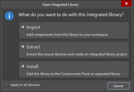
-
In the Open Integrated Library dialog that appears, click the Extract button.
The source schematic and model libraries are extracted and saved in a new folder named after the integrated library's filename in the folder in which the original integrated library resides. A library package (<IntegratedLibraryFileName>.LibPkg) is then created and the source schematic and PCB libraries are added to the project and presented in the Projects panel. Simulation model and sub-circuit files are not automatically added to the project.
Extracting the source libraries from an integrated library – de-compiling to produce a library package project.