
Assembly Assistant
Parent page: Workspace Projects
The Assembly Assistant application in an Altium 365 Workspace provides a browser-based project assembly tool that is based on advanced interaction between the project's detailed BOM data and its 2D/3D assembly view. By bringing these two related sources of assembly data together, the Assembly Assistant delivers an integrated tool that allows assemblers to check and work through the board assembly process from one convenient location.
For those checking a board's assembly prior to manufacture or engaged in the process of manually assembling boards (say, for prototypes or a short run), the Assembly tool provides the required set of graphical and component part information for stepping through the assembly process. This avoids the need for traditional, and potentially error-prone, assembly processes such as manually checking between assembly and BOM printout sheets. To further assist in avoiding manual UI actions during the assembly process, the BOM Assembly tool also offers a full set of shortcut keys for its assembly process actions.
Assembly Assistant Access
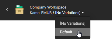
In an Altium 365 Workspace the interactive Assembly Assistant application is available from the WIP view of a specific project, or from the Design Snapshot view of a project Release. Note that the application is also available when viewing a design in your Personal Space.
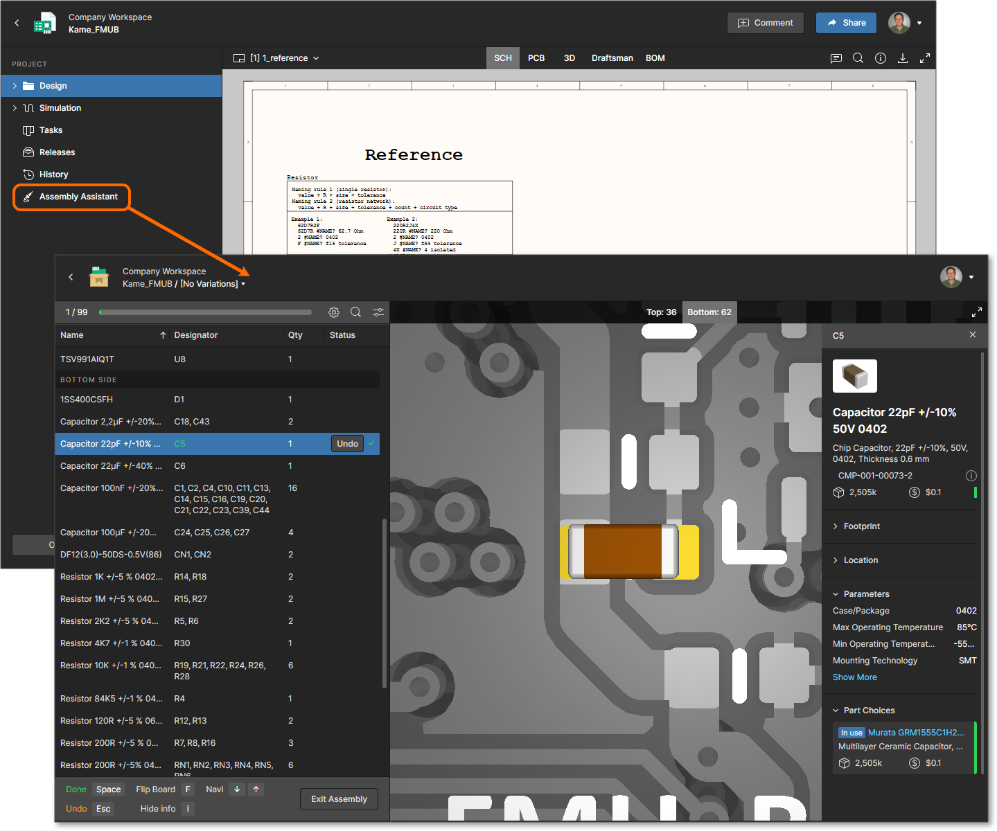
Choose the Assembly Assistant option in the navigation tree to open the Assembly application in its interactive preview mode, and then at any time, invoke the assembly process mode from the ![]() button.
button.
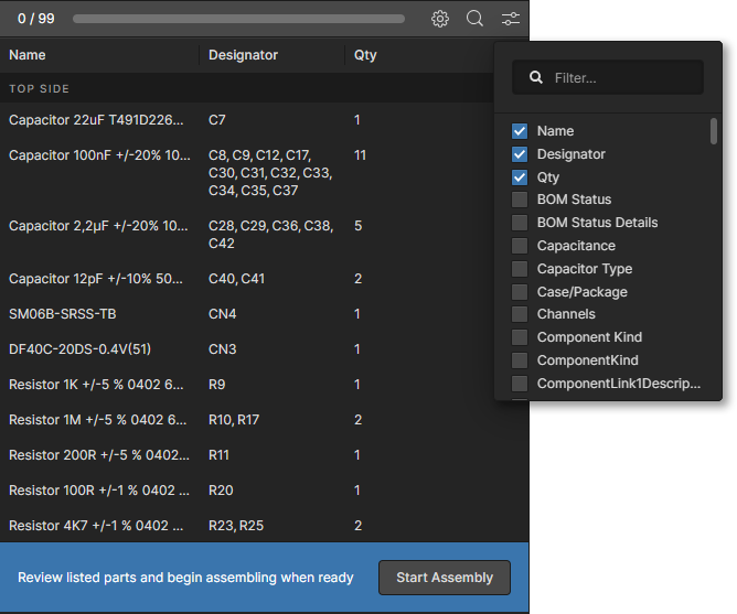
 Access the interactive Assembly BOM view from an opened project or a project Release. Hover over the image to see the active assembly process view. IMAGE 1 IMAGE 2
Assembly Navigation
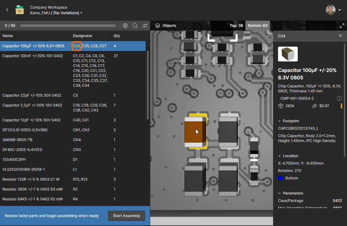
The Assembly Assistant is comprised of a configurable BOM listing pane on the left and an interactive 2D/3D graphical view of the board assembly view on the right. Select any element in the pane or board assembly view to cross-probe between the two, which provides immediate visual interaction between BOM component parts and their physical board placement. In effect, the Assembly Assistant's board/BOM navigation is equivalent to that provided through the project Design view, except that the cross-probe interaction is available from within a single page view rather than between the design view's PCB/3D/BOM mode tabs.
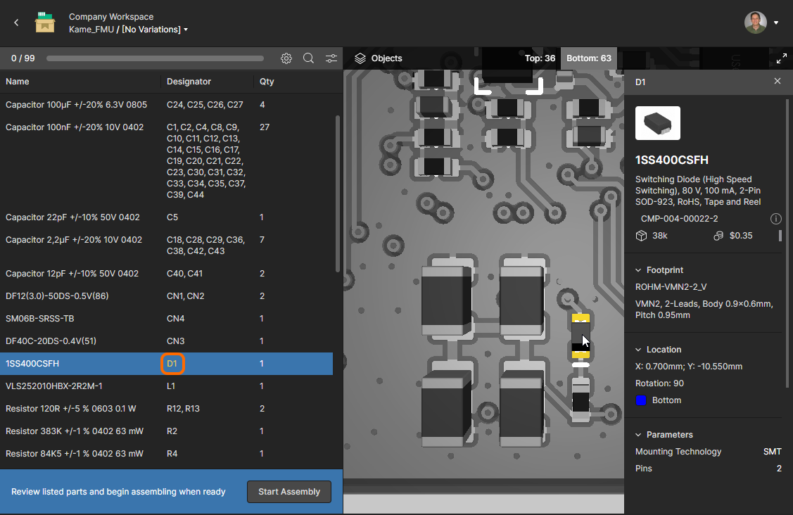
Select an entry row in the BOM listing pane to highlight all of its included components (as indicated by the Designator cell entries) in the assembly view, or select an individual designator to highlight just that component. As you navigate through the BOM assembly elements, the board assembly graphics will pan and zoom when highlighting a selected component (or components) and also flip to the other side of the board where required.
As shown in the below animation, when a selected BOM row includes components fitted to the other side of the board, these are highlighted in a row sublist that includes a Top/Bottom side information note – select this sub entry to cross-probe to the components on the other side of the board, which then populate the selected row entry (highlighted in blue). You can use the Top/Bottom tabs to manually flip the board view, and the R keyboard shortcut to reset the graphics view.
Dynamically cross probe between the BOM pane entries and the board Assembly display by selecting components individually or by group.
Reverse cross-probing is also supported, where components selected in the board 3D view are highlighted in the BOM list table and their details shown in the Information pane.
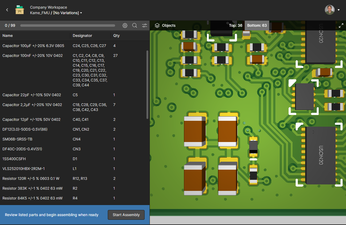
List and View Options
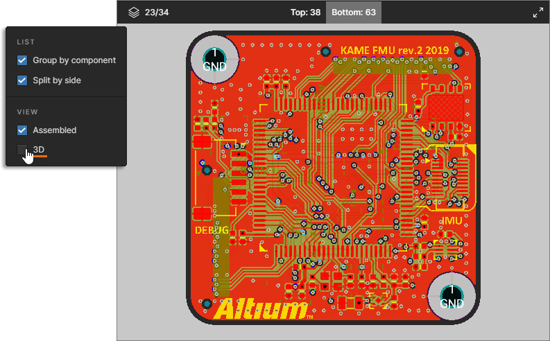
How BOM entries are listed and the Assembly graphics display can be configured from the ![]() button menu at the top of the BOM pane. The options include:
button menu at the top of the BOM pane. The options include:
LIST:
- Group by component – By default, component entries in the BOM list are grouped together by their unique identifiers in the same arrangement as the project BOM. With BOMs composed of Workspace-hosted Managed Components the identifier is a component’s revision (
RevisionID), whereas BOMs with unmanaged, file-based library components the name identifier is used (Name/Comment). Uncheck the Group by component option to revert the listing to a single component for each line.
With the latter (unmanaged) BOM type you can edit the project’s BOM document in Altium Designer by adding other component identification parameters (say IPN or SKU, for example) to more precisely differentiate between components. See Identifying Identical Components in Altium Designer’s ActiveBOM page for more information.
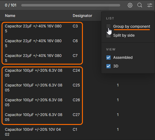
- Split by side – Separate the BOM listing into Top and Bottom -side sections, where each section includes components placed on that board side (default setting). When unchecked, top and bottom side components are included together, but separated as a sub-entry when the row is selected – see Assembly Navigation, above.
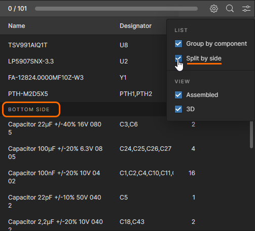
VIEW:
- Assembled – Show component 3D bodies (default), therefore visualizing the assembled board, or only show the component positions when unchecked. Applies to 3D mode only.
- 3D – Show the board assembly graphics in 3D (default) or in 2D when unchecked.
Column Options
Use the ![]() button menu to enable/disable component parameter data columns in the BOM table. The column list includes all defined Workspace component parameters along with any unique parameters defined by BOM components – enter a term in the Filter field to constrain the parameter listing.
button menu to enable/disable component parameter data columns in the BOM table. The column list includes all defined Workspace component parameters along with any unique parameters defined by BOM components – enter a term in the Filter field to constrain the parameter listing.
Header Settings:
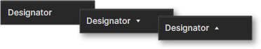
- Click on a data column header to sort the BOM listing by that parameter value. Repeated click to cycle the column sort setting between ascending or descending order (as indicated by the associated arrow icons) or to the listing's default sort order.
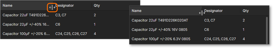
- Select and drag a header's end border to adjust its column width.
- Note that like the project's Workspace BOM view, the Assembly Assistant's BOM list columns also support BOM column Alias names, as added to an ActiveBOM document in Altium Designer.
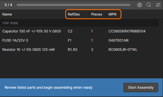
Assembly Process Flow
Invoke the Assembly Assistant's tracked assembly process mode from the ![]() button. In this mode, each BOM entry can sequentially be checked off (marked as done) as the assembly process proceeds, which provides a convenient audited version of the BOM that tracks the board assembly progress. Note that a set of selectable progress command options and keyboard shortcuts are displayed at the bottom of the BOM pane.
button. In this mode, each BOM entry can sequentially be checked off (marked as done) as the assembly process proceeds, which provides a convenient audited version of the BOM that tracks the board assembly progress. Note that a set of selectable progress command options and keyboard shortcuts are displayed at the bottom of the BOM pane.
 Step through the interactive assembly process by marking component BOM entries as done or skipped.
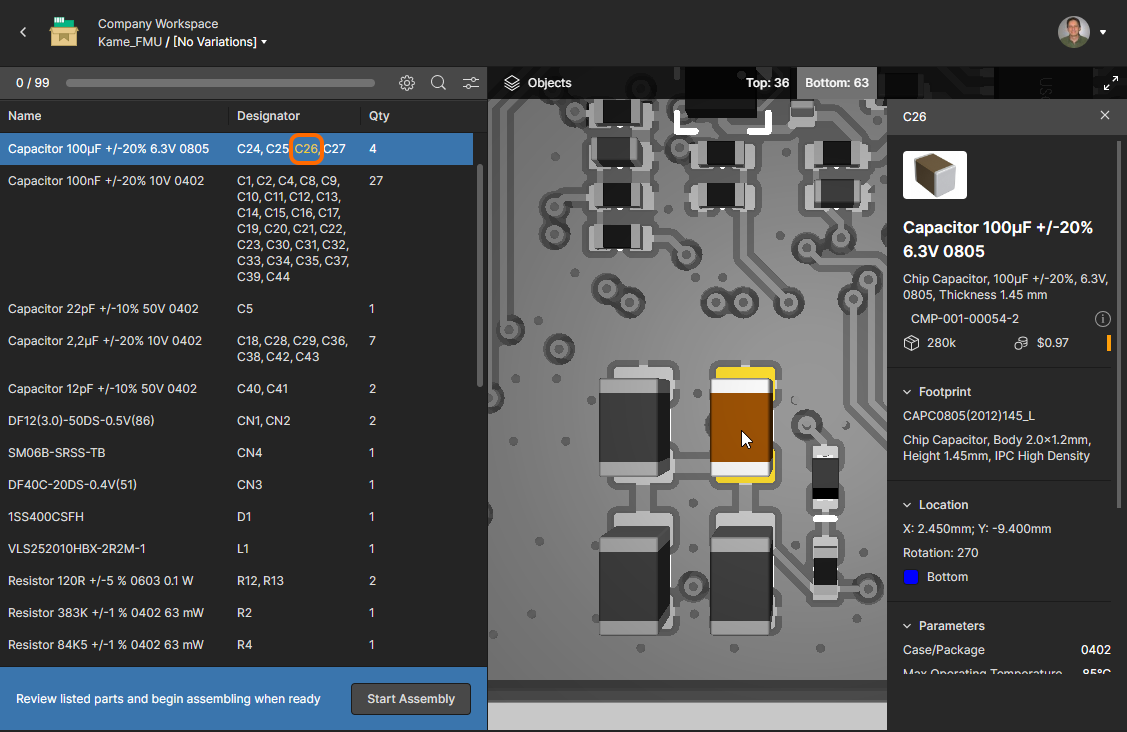
As each BOM entry is selected you are free to navigate through its constituent components to determine their exact board location and orientation (see Assembly Navigation, above) – in this mode, components initially are highlighted by board position rather than as 3D bodies. When you have finished checking or fitting those component parts, the BOM entry can be toggled to a completed status by selecting ![]() (spacebar). The checked-off components are then shown as full 3D bodies (not available in 2D view mode), the assembly process automatically moves to the next BOM entry, and the completed entry is indicated by green designator text and a status marker. Note that you can revert the status of a completed BOM entry by selecting it and clicking its
(spacebar). The checked-off components are then shown as full 3D bodies (not available in 2D view mode), the assembly process automatically moves to the next BOM entry, and the completed entry is indicated by green designator text and a status marker. Note that you can revert the status of a completed BOM entry by selecting it and clicking its ![]() button.
button.
While the assembly process steps through sequentially, you can select any BOM entry in the list to deal with that particular component part. A BOM entry also may be specifically bypassed by selecting Skip (escape key), which will mark that entry accordingly – note that the assembly process cannot be completed if entries are marked with a Skipped status or no status.
Full BOM information for the currently selected component(s) is available from the Information pane on the right, which is opened by the Show info command (or I keyboard shortcut). The Information pane is populated by component data drawn from the source documents or from an ActiveBOM document, if available. The latter option provides full and current data for the selected components(s) including lifecycle status, manufacturer part choices, and supplier pricing and availability. Note that as shown in the below animation, the components displayed for a BOM entry that has been checked off (marked as Done) are displayed as 3D bodies.
Enable the Information pane to see detailed BOM data for the currently selected component. The visual placement display of a component marked as Done changes to its 3D body graphic.
When all BOM entries have been marked as done and the assembly process is complete, this is reported in the status section at the bottom of the BOM pane along with the number of placed component pins and the elapsed time of the assembly process. To restart the assembly process, use the ![]() button to reset the Assembly Assistant to its initial state.
button to reset the Assembly Assistant to its initial state.
 A completed assembly process where all BOM entries have been marked as Done. The BOM pane includes relevant status information.